manuals.online logo
Brands
  1. Home
  2. •
  3. Brands
  4. •
  5. MasterTop
  6. •
  7. Automobile Accessories
  8. •
  9. MasterTop 15433301 User manual

MasterTop 15433301 User manual

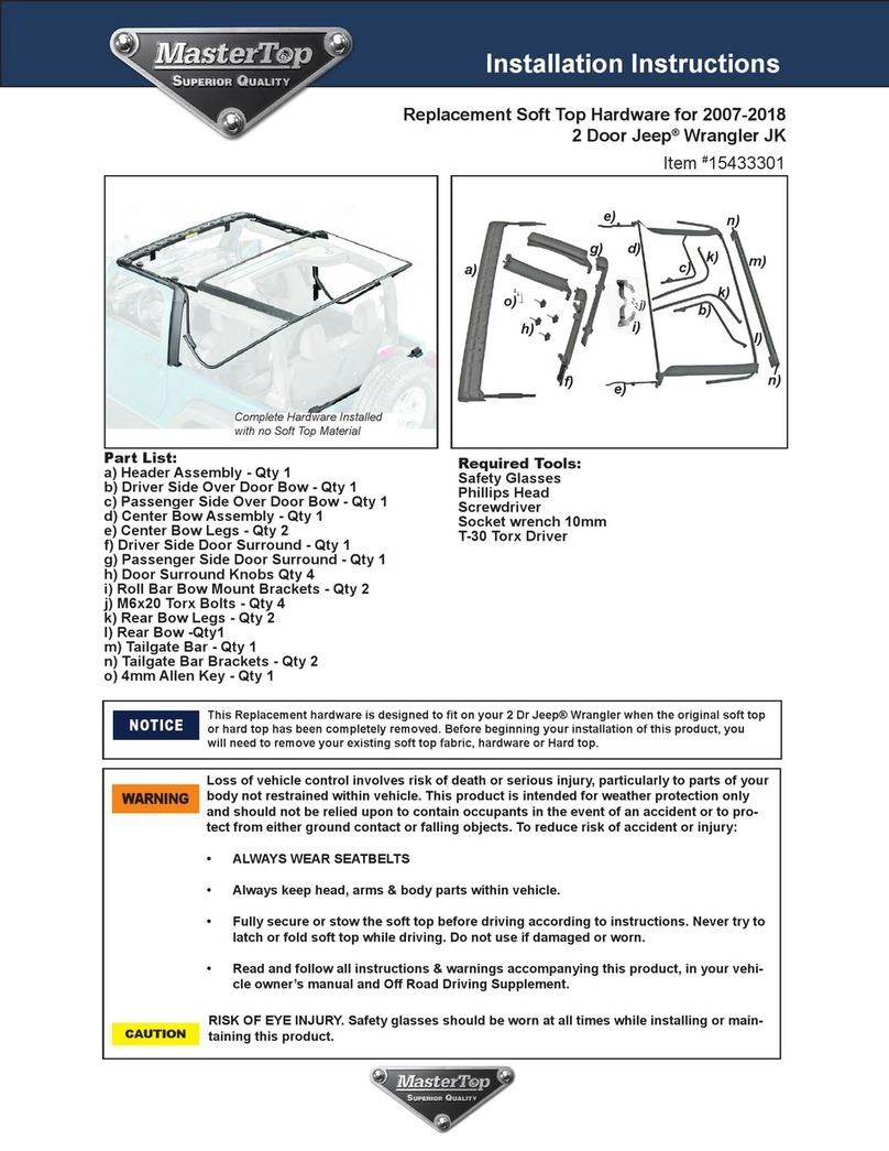
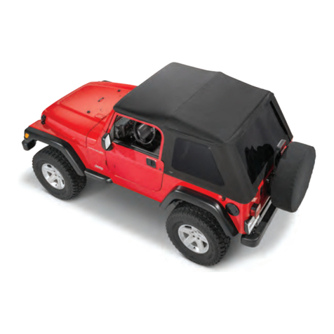
Replacement Soft Top Hardware for 2007-2018
2 Door Jeep®Wrangler JK
Item #15433301
Loss of vehicle control involves risk of death or serious injury, particularly to parts of your body not
restrained within vehicle. This product is intended for weather protection only and should not be relied
upon to contain occupants in the event of an accident or to protect from either ground contact or
falling objects. To reduce risk of accident or injury:
•ALWAYS WEAR SEATBELTS
• Always keep head, arms & body parts within vehicle.
• Fully secure or stow the soft top before driving according to instructions. Never try to latch or fold
soft top while driving. Do not use if damaged or worn.
• Read and follow all instructions & warnings accompanying this product, in your vehicle owner’s
manual and Off Road Driving Supplement.
RISK OF EYE INJURY. Safety glasses should be worn at all times while installing or maintaining this
product.
Part List:
Header Assembly - Qty 1
Driver Side Over Door Bow - Qty 1
Passenger Side Over Door Bow - Qty 1
Center Bow Assembly - Qty 1
Center Bow Legs- Qty 2
Driver’s Side Door Surround - Qty 1
Passenger Side Door Surround - Qty 1
Door Surround Knobs - Qty 4
Roll Bar Bow Mount Brackets - Qty 2
M6x20 Torx Bolts- Qty 4
Rear Bow Legs- Qty 2
Rear Bow- Qty 1
Tailgate Bar- Qty 1
Tailgate Bar Brackets- Qty 2
Required Tools:
Safety Glasses
Phillips Screw Driver
Flat Head Screw Driver
T-20 Torx Driver
This Replacement hardware kit is designed to fit on your 2 Dr Jeep® Wrangler when the original soft
top or hard top has been completely removed. Before beginning your installation of this product,
you will need to remove your existing soft top fabric, hardware or Hard top.
WARNING
CAUTION
NOTICE
Installation Instructions
Important Safety information
Your MasterTop® Replacement hardware is intended to be used with other MasterTop Products to increase the fair weather
enjoyment of your off-road capable vehicle. Before installation, please take a moment to review the following safety information
and installation instructions. Important safety information is generally preceded by one of three signal words indicating the
relative risk of injury. The signal words mean:
a hazardous situation which, if not avoided, could result in death or serious injury. You CAN be KILLED
or SERIOUSLY HURT if you don’t follow instructions.
WARNING
CAUTION
NOTICE
a hazardous situation which, if not avoided, could result in minor or moderate injury. You CAN be mo-
derately HURT and also may suffer property damage if you don’t follow instructions.
Careful attention is required to this instruction or operation but does generally not relate to personal
injury. Damage to your MasterTop product or other property may result if you don’t follow instruc-
tions.
2
“Quick” Attach the Deck Fabric to
the Windshield Header
Locate the front header and place on a table (FIG 1).
using a drill and Phillips head bit, loosen but do not
remove the screws located on the top plate of the
header. With the soft top underside (substrate) facing
up and top of the Windshield header also facing up,
center the front tube sewn onto the deck onto the
header and push the front tube into the space created
when you loosened the top plate screws. Working from
the center out to each side, push the tube into the slot
securing it into the header.
Note: if necessary, to help you insert this tube you may
want to use an ice scraper or plastic putty knife to push
the tube into the slot (FIG's 2, 3, & 4).
When the fabric is in the header and you know it
is centered, tighten the screws on the header
securing the fabric to the header (FIG 5) including the
four corner screws (FIG 6).
Flip the Header over so the underside is facing up . Slip
the corner pocket sewn into the top between the
header and position the cable anchors over the two
holes with the cable facing the outside of the header
(FIG 7).
Wrap the plastic tab over the cable anchors and
reinstall the screws securing the
fabric/cable anchors to the header (FIG 8).
Before you begin Installation:
We are excited that you have chosen the MasterTop Replacement Soft Top Hardware Kit. This high-quality hardware is
designed to provide a structure for your replacement soft top on your Jeep®. Please note that it is important that you become
familiar with the installation process of this top reading the following instruction sheet and warnings thoroughly.
When unpacking, carefully check to make sure all parts are included. If any part is missing
or broken, please call MasterTop customer service at 720-575-5440.
PRO-Install TIP: Installing a Fabric Soft Top to this hardware System:
If you plan on installing a soft top on this hardware system we highly suggest you install the fabric to the front header before you
install the front header to the vehicle. We have installed thousands of JK tops and have created an easy install method that is
used at the factory. With the front header off the vehicle, this method of installation becomes even easier. Please see below to
install the soft top fabric to the front header before you install the hardware system.
FIG 2
FIG 3 FIG 4
FIG 5 FIG 6
FIG 7 FIG 8
Important Note:
The small piece of
webbing installed on
the center bow with the
hole in it (see left) is
where the soft top
cable spring is
designed to attach.
JK Soft Top Hardware Installation
Step 1: Install Bow Mount Brackets to Roll Bar
3
Locate the (2) bow mounting brackets and (4)
Torx head pivot bracket bolts shown in FIG 9.
Carefully unzip the roll bar padding on the
vertical side tube to expose the two factory
holes in the roll bar (FIG 10).
Locate the bow mounting brackets over the
factory holes making sure the bracket is right
side up as shown in FIG 11 and using the T-20
Torx head pivot bracket bolts, install brackets to
the roll bar (FIG12).
Slip the roll bar padding back over the installed
brackets carefully slipping the bracket mounts
through the slits in the roll bar padding (FIG 13).
Repeat on passenger side.
STEP 2: Assemble the Door Surround
Drip Rails
Locate the Drivers and passengers over door
assemblies and the “drip rail” inserts shown in
FIG14.
Separate out the driver’s side over door assembly
and corresponding drip rail insert as shown in
FIG15.
Locate and line up the three round tabs on the drip
rail with the holes located in the over door assem-
bly as shown in FIG16.
Firmly Squeeze the round tabs down into the
holes permanently securing them to the over door
assembly (See FIG17).
NOTE: It may take a lot of force to squeeze these
tabs into the over door assembly. You may need to
use a rubber mallet or the edge of a table to
secure them completely.
Repeat this procedure for the Passenger
side over door assembly.
FIG 9 FIG 10
FIG 11
FIG 12
FIG 13
Step 3: Pillar and Over Door Surround Assembly
Locate the driver’s side Rear over door assembly and the driver’s side Pillar
assembly shown in FIG18.
Turn the two pieces over as shown in FIG19 and line up the slot on the pillar
assembly with the “T” on the over door assembly. Notice in Fig 19 that there
is a secondary “T” that will be lined up when you slide the long “T” into the
long slot. Slide the two pieces together lining up both “T’s” to secure the top
over door assembly with the Pillar assembly. See FIG's 20 & 21.
Locate the small screw packet in the hardware kit found in the door surround
box. Using a Phillips head screw driver, install the screw into the two screw
holes on the two assembled parts securing them permanently together. See
FIG22
Repeat the above assembly on the Passenger side Rear over door and
pillar assemblies.
FIG 18
FIG 19
FIG 20
FIG 21
FIG 22
FIG 24
FIG 23
Step 4: Install Foam to Front Door
Surrounds
Locate the driver’s side front door
surround and the rectangular piece of
foam found in the door surround
hardware pack. Line up the foam with the
rear of the door surround and measure
the length between the rear of the door
surround and the top of the curve (FIG
23). With a pair of scissors, cut the foam
to size. Remove the backing on the foam
and secure it to the front of the door
surround as shown in FIG24.
Make sure not to cover the hole in the
door surround.
Repeat this procedure on passenger side
door surround.
4
5
Step 5: Install Door Surrounds to Jeep
Locate the assembled Driver’s side rear door
surround On the bottom of the vertical pillar portion
of the assembled door surround is a pin that will be
inserted into the body tub as shown in FIG 25.
Insert the door surround pin into the body tub. After
inserting the pin, locate the upper portion of the
door surround “C” attachment and push onto roll bar
(FIG's 26 & 27).
Make sure the front seal is snug against the
windshield seal as shown in FIG 28. The “C” should
fit in the cutout of the roll bar pad. Line up the
threads in the “C” with the top hole in the roll bar.
Locate the two sets of screw knobs. Line up the door
surround “C” attachment holes with the vertical holes
in the roll bar. Slip the front knob through the hole in
the front door surround (FIG 29).
Tighten the knob securing the front door surround
(FIG 31). Repeat this procedure on the back of the
door surround and on the other side of the vehicle.
Finally, tighten all four knobs. All knobs on both sides
of the vehicle should be secured to the roll bar.
Step 6: Install Bow legs to Center Bow
Locate the center bow assembly and two
center bow legs as called out in FIG 32). Line
up the correct bow leg (Quick release knobs
MUST be facing inwards towards center of
assembly) with the bottom of the center bow
(FIG 33). With the attached set screw, install the
bow leg to the center bow using a Phillips
head screw driver (FIG 34). Repeat on other side
of Center Bow (FIG 35).
Step 7: Install Center Bow to the Vehicle
Locate the center bow assembly put together in
step 6 (Fig 35). With a friend, place the bow
assembly over the roll bar and line up the
assembly to the lower bow mount bracket (Fig's
36 & 37) with the quick release knob facing
inwards. The center of the bow should be towards
the rear of the vehicle as shown in Fig 38 and the rear
bow attached with the two fabric strips should lay on
top of the rear roll bar legs.
Line up the Quick release knuckle with the lower bow
mount bracket attachment and attach each side of the
center bow assembly to the bracket (Figs 39, 40 &
41). Repeat on other side of vehicle.
FIG 37
FIG 32 FIG 33
FIG 34
FIG 35
FIG 36
FIG 38
FIG 39
FIG 40
FIG 41
6
Step 9: Install Over Door Bows to Center
Bow
Locate the two over door bows as called out in FIG
41. The over door Bow legs should fit inside the Door
surrounds(Figs 42 & 43) with the Quick release knob
facing out.
Secure the bows into the door surround clip placing
the round hole into the door surround clip (FIG 44).
Line the quick release knobs on the end of the
header legs up with the Center bow mounting hole
(Fig 45) and attach the quick release knuckles to the
center bow (Fig 46) with the Quick Release knob
facing out. Repeat on other side of vehicle.
FIG 43
FIG 42
Step 10: Install Rear Bow Legs to Bow
Mounts and Rear Bow
Locate the two rear bow legs as called out in FIG
47.These bow legs will be installed on the top bow
mount located on the roll bar (FIG 48). Place the rear
bow leg with the quick Release knob facing out and
the loop portion facing down (FIG 49) while pulling
the quick release knob out, connect the rear bow
leg to the bow mount bracket (FIG's 50, 51 & 52).
Repeat on other side of vehicle
At this point both the center bow and the rear
bow mount legs should be installed on the bow
mount bracket on the roll bar as shown in
FIG 53. The Center bow should be on the lower
bracket and the rear bow should be on the upper
bracket mount.
FIG 49 FIG 50
FIG 51
FIG 53
FIG 44
FIG 52
FIG 41
FIG 47
7
Step 10 Continued: Install Rear Bow Legs to
Bow Mounts and Rear Bow
With the two Rear Bow Legs installed to the Bow
mount Bracket, locate the rear bow called out in FIG
54.On the Bow leg there is a set screw that needs to
be removed. You will use this screw to mount the Bow
Legs to the Rear Bow. With the help of a friend, lift the
rear bow from resting on the roll bar legs and slide it
into the rear bow leg (FIG 55). Once both sides are
secure, use the set screw to mount the rear bow leg
and rear bow (FIG's 56 & 57)
FIG 55
FIG 56
FIG 57
Step 11: Install Over Door Bows to Front Header
Assembly
Locate the Fabric/Header (If you installed the soft top fabric.
If fabric is not installed, locate Header assembly) assembly
as shown in FIG 58. Unlatch each over door bow mount
(FIG 59). On the over door bow assembly, slip the header
sleeve (round Tube) over the header leg (FIG 60).
Insert the “knuckle” installed on the over door bow into the
Header leg on the Header Assembly (FIG 60 & 61) and
using a Phillips head Screw Driver mount the pre-installed
set screw securing the front header and over door bows
(FIG 62)
Slide the bow sleeve over the knuckles as shown in FIG 63.
Repeat this procedure on the opposite side and secure the
over door bow/header assembly back to the door surrounds
(FIG 64)
FIG 59
FIG 64
FIG 54
FIG 61
FIG 58
8
Step 12: Attaching the Tailgate bar Brackets
Locate the Tailgate bar and brackets (FIG 65). Locate the driver’s
side bracket (marked on the bracket) with the lip to the outside of the
vehicle, line up the bracket with the slot in the body tub, hook the
rear portion of the bracket to the body tub and roll the bracket
forward until it clicks.
See FIGs 66, 67, 68. Repeat this procedure on the passenger side.
See the Soft top or Soft accessory instruction sheet for the proper
installation of the tailgate bar into these brackets.
FIG 65
FIG 66 FIG 67 FIG 68
Using your 2 Door JK Hardware
Your Soft top hardware system is designed with a fold back sun roof
feature. To use this feature, slide the over door sleeves forward to
unlock the front hinge. This will allow you to fold the top back into the
sun roof position.
When top is closed, slide sleeves rearward over the hinge to lock
the bow in place.
When you are not using the sun roof feature on
your top the bow sleeves MUST be slid over the
bow hinges.
CAUTION

Other manuals for 15433301

1

Other MasterTop Automobile Accessories manuals

MasterTop SkyMaster 15501 Series User manual

MasterTop

MasterTop SkyMaster 15501 Series User manual

MasterTop ShadeMaker 142017 Series User manual

MasterTop

MasterTop ShadeMaker 142017 Series User manual

MasterTop 142037 Series User manual

MasterTop

MasterTop 142037 Series User manual

MasterTop 15433301 User manual

MasterTop

MasterTop 15433301 User manual

MasterTop 156016XX User manual

MasterTop

MasterTop 156016XX User manual

MasterTop Bimini Top Plus User manual

MasterTop

MasterTop Bimini Top Plus User manual

MasterTop 15420301 User manual

MasterTop

MasterTop 15420301 User manual

MasterTop SkyMaster 158004 Series User manual

MasterTop

MasterTop SkyMaster 158004 Series User manual

MasterTop 8420110X User manual

MasterTop

MasterTop 8420110X User manual

Popular Automobile Accessories manuals by other brands

aFe Power Scorpion 79-21001L instruction manual

aFe Power

aFe Power Scorpion 79-21001L instruction manual

Gazer MMR71 SERIES user manual

Gazer

Gazer MMR71 SERIES user manual

American muscle 94-00 installation instructions

American muscle

American muscle 94-00 installation instructions

Hak-System 12190512PL Fitting instructions

Hak-System

Hak-System 12190512PL Fitting instructions

AA Products X39-SC BOX2 BLK instruction manual

AA Products

AA Products X39-SC BOX2 BLK instruction manual

VBG Onspot Mounting instruction/Spare Parts List

VBG

VBG Onspot Mounting instruction/Spare Parts List

INDIWORK IW04A-4G instruction manual

INDIWORK

INDIWORK IW04A-4G instruction manual

Rival 2333.0334.1 installation manual

Rival

Rival 2333.0334.1 installation manual

GU Electronic Porsche CDR3.1 TD manual

GU Electronic

GU Electronic Porsche CDR3.1 TD manual

Curt Manufacturing 13081 installation instructions

Curt Manufacturing

Curt Manufacturing 13081 installation instructions

POOL-LINE 110054 Assembly instructions

POOL-LINE

POOL-LINE 110054 Assembly instructions

Thule 2021 parts list

Thule

Thule 2021 parts list

DEFA SmartCharge 4A Technical manual

DEFA

DEFA SmartCharge 4A Technical manual

Soundoff Signal MPower PMP2BK004 manual

Soundoff Signal

Soundoff Signal MPower PMP2BK004 manual

Connects2 CTUAR01 instruction manual

Connects2

Connects2 CTUAR01 instruction manual

Directed Directechs DB3 installation guide

Directed

Directed Directechs DB3 installation guide

Pogo Alert+ operating instructions

Pogo

Pogo Alert+ operating instructions

curt 70130 installation manual

curt

curt 70130 installation manual

manuals.online logo
manuals.online logoBrands
  • About & Mission
  • Contact us
  • Privacy Policy
  • Terms and Conditions

Copyright 2025 Manuals.Online. All Rights Reserved.