Bin Master SPL-100 User manual

925-0367 Rev A
1018
SPL-100
BATTERY-OPERATED LASER
OPERATOR’S MANUAL
BinMaster: Division of Garner Industries
7201 N. 98th St., Lincoln,NE 68507
402-434-9102 • info@binmaster.com
www.binmaster.com
INSTALLATION AND OPERATION INSTRUCTIONS
PLEASE READ CAREFULLY

925-0367 Rev A
1018
2
TABLE OF CONTENTS
Warnings ________________________________________________________ 3
Warning Labels ___________________________________________________ 3
FCC Information __________________________________________________ 4
Intended Use ____________________________________________________ 4
Highlights _______________________________________________________ 5
Applications _____________________________________________________ 5
Features ________________________________________________________ 5
Har dware Features __________________________________________________________ 5
Software Features __________________________________________________________ 6
System Architecture _______________________________________________ 6
Specifications ____________________________________________________ 7
Dimensions ______________________________________________________ 8
External Dimensions ________________________________________________________ 8
Weight ____________________________________________________________________ 8
Controls _________________________________________________________ 9
Configuration and Adjustments ______________________________________ 9
User Configuration __________________________________________________________ 9
Factory Configuration Settings ________________________________________________ 9
Assembly _______________________________________________________ 9
Installation______________________________________________________ 10
Operation ______________________________________________________ 10
Maintenance ____________________________________________________ 11
Service Warnings __________________________________________________________ 11
Battery Replacement _______________________________________________________ 11
Reconfiguration____________________________________________________________ 11
Cleaning _________________________________________________________________ 11
Manufacturer and Contact Information _______________________________ 12

925-0367 Rev A
1018
3
WARNINGS
• Caution—use of controls or adjustments or performance of procedures other than
those specified herein may result in hazardous radiation exposure.
• This product emits Class 2 laser radiation, <1mW from the shutter in a direction
perpendicular to the shutter.
• Do not stare into the laser during operation.
• If eyes are exposed to the laser, blink and turn away immediately.
• The unit may begin laser operation immediately upon connecting the battery or at any
time according to the software configurations applied.
• When servicing the unit, it is advised to first disconnect the battery in order to power
the unit off.
• When connecting the battery, first ensure the unit is not pointed toward eyes.
• Do not tamper with or remove the electronics cover.
• Do not tamper with or remove the shutter or shutter attachment means.
WARNING LABELS
This product contains the following warning and certification labels affixed to the exterior of
the body:
Label 1: Certification and Identification Label
The Certification and Identification label is located on the product body side.

925-0367 Rev A
1018
4
Label 2: Warning Logotype
The Warning Logotype label is located on the product body side.
Label 3: Aperture Label
The Aperture label is located on the product front adjacent to the aperture.
Label 4: Brand Label
The Brand label is located on the product body side.
FCC INFORMATION
NOTE: This equipment has been tested and found to comply with the limits for a Class A
digital device, pursuant to part 15 of the FCC Rules. These limits are designed to provide
reasonable protection against harmful interference when the equipment is operated in a
commercial environment. This equipment generates, uses, and can radiate radio frequency
energy and, if not installed and used in accordance with the instruction manual, may cause
harmful interference to radio communications. Operation of this equipment in a residential
area is likely to cause harmful interference in which case the user will be required to correct
the interference at his own expense.
INTENDED USE
The SPL-100 is intended for mounting in fixed, known locations and for use in measuring
distances to solid materials in low and no-dust environments.

925-0367 Rev A
1018
5
HIGHLIGHTS
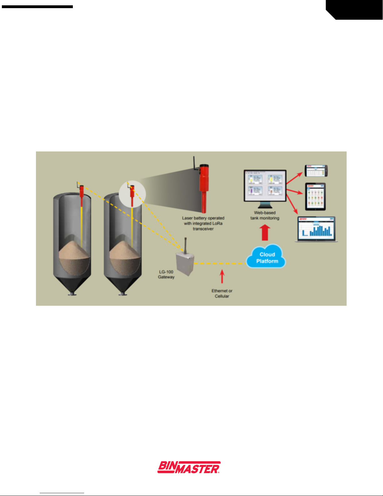
The SPL-100 is a fully wireless, battery-powered automatic single point laser level measuring
sensor. The unit features a dust tube for dust protection. The unit operates at a configurable
time, captures a measurement, and sends the measurement using the integrated LoRa
transceiver to the LoRa modem that may be connected to the LG-100 gateway. The gateway
may be configured to send and receive data and configuration files via BinView.
The unit is supplied with SPL-100 configuration software that runs on modern Windows PCs.
To reduce installation costs and complexity, the unit is completely wireless; neither power
wires nor communications cables are required.
APPLICATIONS
Granules, pellets and solids contained in bins, tanks, silos, or hoppers in low and no-dust
environments. Applications may include:
Plastics
Dry Chemicals
Food Processing
Grain Storage
Paper Processing
FEATURES
Hardware Features
•Single point measuring
•LoRa communication transceiver
•Battery powered
•30 meter (98 feet) measuring range
•Visible range red laser
•Available matched LoRa modem
•2.0" standard NPT Female thread-in mounting
•Sealed to IP67
•¼ Wave whip antenna, IP67 rated
925-0367 Rev A
1018
6
Software Features
•General error reporting
•Fully configurable by MicroUSB
•Partially re-configurable by LoRa
•Configurable LoRa wake-up & measure times
•Cloud-based access (configuration & data)
SYSTEM ARCHITECTURE
Figure 1: System Conf iguration

925-0367 Rev A
1018
7
SPECIFICATIONS
•Measurement range: 30m (98 feet)
•Measurement Accuracy: ±5mm (0.20 inches)
•Data I/O: LoRa
•Configuration I/O: LoRa and Micro USB (under sealed cover)
•Wireless Communications Range:
o>10km (>6 miles) Line-of-Sight (LOS)
o>1.6km (>1 mile) Non-Line-of-Sight (NLOS) (Dependent upon terrain and line of
sight obstacles)
•Power Source: 3.6V, 19AH Internal Li-Ion battery
•Battery Life (Est.): ~10 years, one measurement per day
•Antenna: ¼ Wave Whip
•Dust Tube: Available
•Ingress Protection: IP67
•Ambient Operating Temperature: -30 to +85C
•Ambient Storage Temperature: -40 to +85C
•Battery Voltage Reporting: Configurable
•Receiver Addressing: Configurable
•Hazardous Location: Not rated for hazardous locations
•Mounting: 2.0" NPT standard threaded nose, multiple mounting flange types
•Laser Beam Size: 2.5 x 5 mm @ 3 meter (FWHM)
•Laser Wavelength: 635 ± 10nm
•Laser Safety: <1 mW (Class 2)
•Laser Emissions Direction: Collimated and perpendicular to the aperture face.
•Housing Material: Aluminum and Injection molded plastic

925-0367 Rev A
1018
8
DIMENSIONS
External Dimensions
Figure 2: Dimensions (units in mm)
Weight
Approximate weight:
1.8kg
4 pounds

925-0367 Rev A
1018
9
CONTROLS
The unit has no user controls. Factory supplied configuration may be changed using SPL-100
configuration software as described in Configuration below.
CONFIGURATION AND ADJUSTMENTS
Before installation, users may wish to change the factory confirmation.
User Configuration
The following configurations may be set by users:
•Measurement times and frequency
•Power consumption reporting to help predict when the battery must be replaced.
•Transmission frequency
The unit may be configured using the supplied configuration software via the MicroUSB
connector located under the Battery Cap or over LoRa.
The LoRa configuration method is intended primarily to allow units installed in field
applications to be reconfigured. New configurations will only be received and applied when
the unit wakes at its previously configured wake time.
Factory Configuration Settings
Measurement time: 8AM US EST
Measurement frequency: 24 hours
Power consumption reporting: On
ASSEMBLY
The unit is supplied fully assembled and requires no user assembly other than attachment of
antenna and insertion of battery.

925-0367 Rev A
1018
10
INSTALLATION
The unit may be installed using the 2.0” NPT female threaded nose by threading the unit into
a suitable flange equipped with a 2.0” NPT male threaded receptacle. Using this method, the
unit should be hand-tightened-only to compress the O-ring seal for water-tightness. The unit
should be rotated and additional 1/8 – 1/4 turn after the mounting flange assembly contacts
the O-ring.
The laser may be temporarily continuously activated for 1 minute during mounting to facilitate
aiming. Continuously activating the laser consumes battery power and may reduce the life of
the laser emitter and should be used sparingly to avoid excessive power consumption. Each
time the battery cover is closed, the laser will activate for ~1 minute.
OPERATION
The unit is factory supplied with no battery installed.
When the battery is installed and the battery cover is closed, the unit will begin normal
operation following factory or user-applied configuration settings. The laser will come on for
60 seconds to aid in aiming the unit.
During normal operation the unit is programmed to wake, make and send a measurement,
then return to low-power sleep mode.
When a measurement is initiated the following sequence will occur:
1. The laser is activated
2. A measurement is taken
3. Measurement data is transmitted along with any reporting codes
4. Any available reconfiguration files are received and applied
5. The unit returns to low-power sleep mode
To start the unit:
1. Remove the battery cap
2. Open the battery cover
3. Insert the battery
4. Close the battery cover
5. Replace the Battery Cap

925-0367 Rev A
1018
11
MAINTENANCE
The unit may require periodic servicing for the following reasons:
1. Battery replacement
2. Reconfiguration
3. Cleaning
The unit does not require maintenance or servicing to remain in compliance with CFR Title 21
1040.10.
Service Warnings
Disconnect the battery before servicing the unit.
If it is impossible to disconnect the battery prior to servicing, take precautions to prevent the
laser aperture located on the shutter from being pointed at eyes.
Do not tamper with or remove the electronics cover.
Do not tamper with or remove the shutter or shutter attachment means.
Battery Replacement
For battery replacement, remove the battery cap. Open the battery cover. Remove the
battery and replace with a new battery. Close the battery cover and replace the battery cap.
Batteries can be purchased from BinMaster. Contact your RSM for pricing and availability.
Reconfiguration
Reconfiguration of the unit may be accomplished over LoRa or using the MicroUSB
connector located under the MicroUSB cover on the back end of the unit.
Cleaning
The exterior of the unit may require periodic cleaning. Simply wipe the unit with a soft damp
cloth. Mild detergent may be used as required.

925-0367 Rev A
1018
12
MANUFACTURER AND CONTACT
INFORMATION
BinMaster
7201 North 98th Street
PO Box 29709
Lincoln, NE 68507
Phone: 402-434-9102 / 800-278-4241 (toll-free in the U.S. only)
Fax: 402-434-9133
Email: info@binmaster.com
www.binmaster.com
Table of contents


