Leica DNA 10 User manual

Chapter 9
DNA 10 Digital Level
Table of Contents
A. Raw Data ................................................................................................................9-2
B. Equipment..............................................................................................................9-2
1. Instrument and Tripod Setup...............................................................................9-3
C. Level Operation......................................................................................................9-4
1. Job Setup............................................................................................................9-4
D. Collimation Error Correction ................................................................................9-9
E. Check and Adjust Procedure..............................................................................9-10
1. A x Bx Method...................................................................................................9-12
2. A x Bx Method...................................................................................................9-19
F. Line Leveling........................................................................................................9-23
1. Setup ................................................................................................................9-23
2. Starting the Run................................................................................................9-28
3. Check Shots......................................................................................................9-34
G. Allowable Misclosure..........................................................................................9-37
H. Transferring Data.................................................................................................9-40
I. Warning Messages................................................................................................9-40
1. Meas. below limit! .............................................................................................9-41
2. Distance Bal. too big!........................................................................................9-43
3. Meas. Dist too big!............................................................................................9-44

DNA 10 Digital Level
9-2 Revised December, 2012
9. DNA 10 Digital Level
The Leica DNA 10 level is the latest digital level utilized by WYDOT. These levels began
replacing the older Leica NA2002 digital levels in 2004. There are several advantages inherent
with digital levels:
Typically, readings can be taken faster with a digital level than with an optical level.
Increased accuracy can be achieved by taking and averaging multiple readings.
Human errors associated with reading and recording observations are eliminated.
Any digital level can also be used as an optical level. By not turning the instrument on, the
instrument crosshairs may be used in the same manner as an optical level.
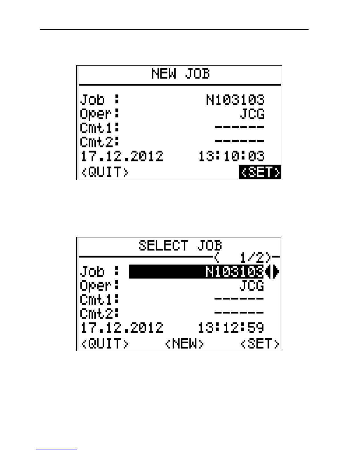
A. Raw Data
The collected data is stored in the instrument's internal memory. After the level line or loop has
been collected, the data is transferred via memory card to a desktop computer or laptop where it
is saved as a *.GSI file. WYDOT field office personnel can send this file along with a copy of
the field notes to the State Photogrammetry & Surveys Engineer. The raw data will be processed
with Leica Geo Office (LGO) software and the results sent back. Refer to Chapter 10 in this
manual for more information on transferring survey data.
There is a limited amount of space in the instrument's internal memory. The digital level is able
to store a maximum of 13 jobs. When the maximum number of jobs are stored in the internal
memory and another job creation is attempted, the message "Memory full!" will be displayed.
When this occurs, one or more of the stored jobs will need to be deleted before another one can
be created.
The internal memory will store a maximum number of turns (i.e. backsight and foresight shots)
within a single job. The total number is set at approximately 450 turns. When approaching the
maximum amount, the message "Job is almost full!" will be displayed. The operator will have a
total of 8 turns to finish the level run. If it will take more than 8 turns, the instrument person will
have to find a place to end the run (e.g. monument, flight line target, or hub). The line or loop
can be continued in another job. When the data is processed, the *.GSI files from separate jobs
can be combined to complete the line or loop.
When the maximum number of measurements has been reached, the message "Actual job is
full!" will be displayed. At this point, the instrument will not store additional measurements for
the level run. The message "Store data in another job!" will then be displayed. Therefore, it is
important to ensure there is enough internal memory available before starting a level run.
B. Equipment
The following equipment is necessary to complete level lines or loops with the DNA 10 digital
level.
DNA 10 digital level.
Battery and battery charger.
Memory card.

Chapter 9
Revised December, 2012 9-3
Fixed-legged tripod.
Bar-coded level rod.
Field book.
Temporary turning platform (turtle).
1" x 1" wooded hubs or railroad spikes (used for the peg test).
1. Instrument and Tripod Setup
As shown if Figure 9-2, place the digital level on the tripod and tighten the central fixing
screw to securely fasten the level to the tripod. Turn the tribrach foot screws to their middle
positions. Set the tripod such that the tripod plate is as level as possible. Using the foot pegs
on the tripod, firmly press the leg points into the ground. Center the circular bubble by
adjusting the foot screws.
Figure 9-1. Instrument and tripod setup.

DNA 10 Digital Level
9-4 Revised December, 2012
C. Level Operation
1. Job Setup
Turn on the DNA 10 by pressing the on/off button, indicated by the red arrow.
Figure 9-2. On/off button
After the level is turned on, the MEAS & REC screen will be displayed.
Figure 9-3. Measure and record screen.

Chapter 9
Revised December, 2012 9-5
To start a new job press the PROG button (red oval).
Figure 9-4. Program and enter Buttons.
When the PROGRAMS menu is displayed, use the yellow navigation buttons (red oval in
Figure 9-6) to scroll down to option 2, LINE LEVELLING. Press the red Enter button (red
square in Figure 9-4) or just press the 2button (red circle in Figure 9-6).
Figure 9-5. Programs menu.

DNA 10 Digital Level
9-6 Revised December, 2012
Figure 9-6. Navigation buttons.
At the LINE LEVELLING menu, create a new job. Highlight option 1, Job and press the
Enter button or press the 1button.
Figure 9-7. Line leveling menu.

Chapter 9
Revised December, 2012 9-7
At the NEW JOB menu, type in the job name (up to 16 characters). Use the white SHIFT
button (red oval in Figure 9-9) to alternate between numerical digits and alphabetical letters/
special characters. After typing the job name, press Enter and type in the operator’s name or
initials then press Enter again.
Figure 9-8. Create new job.
Figure 9-9. Shift button.

DNA 10 Digital Level
9-8 Revised December, 2012
Use the navigation buttons to scroll down to highlight SET, then press Enter. The message
"Job Set!" will be briefly displayed.
Figure 9-10. New job settings.
To open an existing project from the LINE LEVELLING menu (see Figure 9-7), choose
option 1, Job and press the Enter button. At the SELECT JOB menu, use the left or right
navigation buttons to select the appropriate project. Then use the navigation buttons to scroll
down and highlight SET and press Enter.
Figure 9-11. Select job.

Chapter 9
Revised December, 2012 9-9
At the LINE LEVELLING menu, use the up and down navigation buttons to scroll down and
highlight END, then press the Enter button.
Figure 9-12. Line leveling.
D. Collimation Error Correction
The collimation error is the vertical angle between the actual line-of-sight and the ideal
horizontal line.
Figure 9-13. Collimation error.
With the DNA 10, optical and electronic collimation errors can occur. Staff readings are
automatically corrected for the electronic collimation error and stored in the instrument. Optical
collimation errors are eliminated by adjusting the reticle (cross-hairs) with the ocular (eye-piece).
A check and adjust procedure (two-peg test) is performed to determine the collimation error and
should be conducted on a regular basis. At a minimum, a two-peg test should be performed at
the beginning a every job or when the instrument has been significantly jarred. The level should
be allowed to acclimate to the ambient temperature for at least 10 minutes before starting the
two-peg test.

DNA 10 Digital Level
9-10 Revised December, 2012
E. Check and Adjust Procedure
At the PROGRAMS menu, highlight option 4, CHECK & ADJUST and press the Enter button.
Figure 9-14. Check & Adjust.
In the CHECK & ADJUST menu, the job that was previously created should be active. Highlight
option 2, Meth. to choose a two-peg test method then press Enter.
Figure 9-15. Two-peg test.

Chapter 9
Revised December, 2012 9-11
Use the left or right navigation arrow buttons to select A x x B or A x Bx.
Figure 9-16. Select peg test method.
Once the peg test method has been selected, use the up and down navigation arrow buttons to
scroll down and highlight SET. Leave the Stf1 and Stf2 lines blank. Press the Enter button to
continue. The message "Method Set!" will be briefly displayed.
Figure 9-17. Set the peg test method.

DNA 10 Digital Level
9-12 Revised December, 2012
At the CHECK & ADJUST menu, highlight option 3, START and press the Enter button to begin
the two-peg test.
Figure 9-18. Start the peg test.
1. A x Bx Method
Pound a 1" x 1" wooden hub or railroad spike in the ground at stations A and B. The
distance between A and B is approximately 30 meters. When performing a two-peg test,
choose a site with reasonably level terrain.
Figure 9-19. A x Bx method.

Chapter 9
Revised December, 2012 9-13
For the first set of measurements, the instrument is setup at position 1 while the level rod is
set on a hub or spike at station A. At the CHECK & ADJUST screen, press the Enter button
to continue.
Figure 9-20. First peg test setup.
Aim the instrument at the level rod located at station A. If necessary, adjust the focusing
knob (indicated by the blue arrow in Figure 9-21) to clearly focus the cross-hairs on the level
rod.
Figure 9-21. Focus knob and measure button.

DNA 10 Digital Level
9-14 Revised December, 2012
To take the first measurement, press the red measure button on the right side of the
instrument (indicated by the red arrow in Figure 9-21). The DNA 10 will average three
readings for each measurement.
Figure 9-22. Ready for measurement.
After the first measurement has been taken, record the rod reading and distance for A1 in the
field book. Accept the measurement and continue by pressing Enter.
Figure 9-23. First measurement.

Chapter 9
Revised December, 2012 9-15
For the second measurement, the instrument remains at position 1 while the level rod is
moved to a hub or spike at station B.
Figure 9-24. Ready for measurement.
After the second measurement has been taken, record the rod reading and distance for B1 in
the field book. Accept the measurement and continue by pressing Enter.
Figure 9-25. Second measurement.

DNA 10 Digital Level
9-16 Revised December, 2012
When the CHECK & ADJUST screen is displayed, move the instrument to position 2 while
the level rod remains at station B. Press the Enter button to continue.
Figure 9-26. Second two-peg test setup.
The instrument is now ready for the second set of measurements.
Figure 9-27. Ready for measurement.

Chapter 9
Revised December, 2012 9-17
After the measurement has been taken, record the rod reading and distance for B2 in the field
book. Accept the measurement and continue by pressing Enter.
Figure 9-28. First measurement.
For the second measurement, the instrument remains at position 2 while the level rod is
moved to station A.
Figure 9-29. Ready for measurement.

DNA 10 Digital Level
9-18 Revised December, 2012
After the second measurement has been taken, record the rod reading and distance for A2 in
the field book. Accept the measurement and continue by pressing Enter.
Figure 9-30. Second measurement.
The collimation results will be computed and displayed as shown in Figure 9-31. The
difference between the old and new collimation errors should not be greater than ± 15". If
the difference is greater than ± 15", then another peg test will need to be performed. If the
2nd peg test is still greater than ± 15", the instrument may need to be calibrated by a Leica
technician.
Figure 9-31. Collimation results.
When the difference is within the 15" tolerance, note all of the collimation information in the
field book. Press Enter to set the new collimation value in the instrument. The message
"New Collimation Set!" will be briefly displayed. At this point the instrument should be at
the PROGRAMS menu.

Chapter 9
Revised December, 2012 9-19
2. A x Bx Method
Pound a 1" x 1" wooden hub or railroad spike in the ground at stations A and B. The
distance between A and B is between 45 and 60 meters. When performing a two-peg test,
choose a site with reasonably level terrain.
Figure 9-32. A x x B method.
In the CHECK & ADJUST menu, highlight option 2, Meth. to choose a two-peg test method
then press Enter (see Figure 9-15). Use the left or right navigation arrow buttons to select the
A x x B two-peg test method (see Figure 9-16). Once the two-peg test method has been
selected, use the up and down navigation arrow buttons to scroll down and highlight SET.
Leave the Stf1 and Stf2 lines blank. Press the Enter button to continue (see Figure 9-17).
The message "Method Set!" will be briefly displayed. At the CHECK & ADJUST menu,
highlight option 3, START and press the Enter button to begin the two-peg test (see Figure 9-
18).
For the first set of measurements, the instrument is setup at position 1 while the level rod is
set on a hub or spike at station A. At the CHECK & ADJUST screen, press the Enter button
to continue.
Figure 9-33. First two-peg test setup.

DNA 10 Digital Level
9-20 Revised December, 2012
After the first measurement has been taken, record the rod reading and distance for A1 in the
field book. Accept the measurement and continue by pressing Enter.
Figure 9-34. First measurement.
For the second measurement, the instrument remains at position 1 while the level rod is
moved to a hub or spike at station B.
Figure 9-35. Second measurement.
After the second measurement has been taken, record the rod reading and distance for B1 in
the field book. Accept the measurement and continue by pressing Enter.
Table of contents
Other Leica Laser Level manuals

Leica
Leica Rugby 670 User manual

Leica
Leica Rugby 640G User manual

Leica
Leica Rugby 200 User manual

Leica
Leica Rugby 810 User manual

Leica
Leica Rugby 620 User manual

Leica
Leica Lino L360 User manual

Leica
Leica Rugby 300 SG User manual

Leica
Leica iCON robot 60 User manual

Leica
Leica TS12 Lite User manual

Leica
Leica Lino L4P1 User manual

Leica
Leica Rugby 820 User manual

Leica
Leica Lino P5 User manual

Leica
Leica TPS1200 series User manual

Leica
Leica Sprinter 150 User manual

Leica
Leica Rugby 260SG User manual

Leica
Leica LS10 User manual

Leica
Leica Jogger 20 User manual

Leica
Leica N3-70 User manual

Leica
Leica Rugby 410 User manual

Leica
Leica Rugby 880 User manual