Bin Master BMRX-300 User manual
Operating Instructions
Please Read Carefully
BMRX-300
Rotary Level Indicator
BinMaster: Division of Garner Industries LLC
7201 N. 98th St.
Lincoln, NE 68507
402-434-9102
info@binmaster.com | www.binmaster.com
925-0417 REV A 0124

925-0417 REV A 2 0124
BMRX-300 DC Rotary Level Indicator
GENERAL SPECIFICATIONS............................................................................................ 3
SAFETY SUMMARY .......................................................................................................... 4
1.0 INTRODUCTION ......................................................................................................... 5
2.0 INSTALLATION............................................................................................................ 5
2.1 Mounting Summary..................................................................................... 5
2.2 Location and Mounting ............................................................................... 7
2.3 Input Power and Field Wiring ..................................................................... 9
2.4 Grounding ................................................................................................. 10
3.0 DPDT RELAY.............................................................................................................. 10
3.1 Fail Safe High ............................................................................................ 10
3.2 Fail Safe Low ............................................................................................. 10
3.3 Status LED..................................................................................................11
3.4 Status Relay................................................................................................11
3.5 Time Delay ..................................................................................................11
3.6 Changing the Time Delay .......................................................................... 12
4.0 WARRANTY AND CUSTOMER SERVICE............................................................... 13
4.1 Limited Warranty....................................................................................... 13
4.2 Customer Service ..................................................................................... 13
5.0 DISPOSAL ................................................................................................................. 13
TABLE OF CONTENTS

925-0417 REV A 3 0124
BMRX-300 DC Rotary Level Indicator
SPECIFICATIONS
BMRX-200 DC GENERAL SPECIFICATIONS
Power Supply: 12 to 24 VDC
Supply Tolerance: -15% to +10%
Load: AC Models 6 VA
Fuse: 2 AMP 250V TR5 Time Lag PCB mount
Ambient Temperature: (Electronics) -40° F to +158° F (-40° C to +70° C)
Process Temperature: 400° F (204° C)
Enclosure Type: 4X / IP66
Enclosure Material: Die cast aluminum, powder coat nish
DPDT Relay Output: 10 Amps 250 VAC
Fail Safe: Switch selectable "High" or "Low" level modes
Time Delay: Selectable 5 seconds (default); programable to 30 seconds
LED Status Indication: Paddle rotating Rotating GREEN
(optional) Paddle covered Solid RED
Instrument Fault Flashing YELLOW
Status Relay Output: 200V 1.5Amp AC or DC SPST-Normally Open
Mounting: 1-1/4” NPT, 1-1/2" NPT, 1-1/2" Tri-clover
Conduit Entries: 3/4" NPT
Shaft Seal: 1/2 micron, 30 PSI

925-0417 REV A 4 0124
BMRX-300 DC Rotary Level Indicator
SAFETY
SAFETY SUMMARY
Review the safety precautions to avoid injury and prevent damage to equipment.
The product should be installed, commissioned, and maintained by qualied, authorized
personnel only.
Install according to instructions and comply with all National and Local codes.
Use electrical wire that is sized and rated for the maximum voltage and current of the
application. Properly ground the enclosure to an adequate earth ground.
Observe terminal and relay contact ratings on the nameplate and in the installation manual.
Ensure the enclosure cover is in place and secured tightly during normal operation. In
potentially wet environments, thoroughly seal all conduit entries.
If this product is used in a manner not specied by the manufacturer safety protection could
be compromised.
Safety Terms and Symbols
WARNING: Warning statements identify conditions or practices that could result
in injury or loss of life. Risk of electrical shock.
CAUTION: Caution statements identify conditions or practices that could result in
damage to this product or other property.

925-0417 REV A 5 0124
BMRX-300 DC Rotary Level Indicator
INTRODUCTION
1.0 INTRODUCTION
The BinMaster BMRX-300 is a rotary level sensor that provides reliable point level detection
in bulk solids, including powder, pellet, and granular materials. The unit's status is continually
monitored, and its fail-safe circuitry will fail to a "safe" condition on the event of a failure or power
failure. A visual LED array continually indicated the sensors status, giving a quick visual of paddle
rotation, covered condition or fault condition. A status relay output is also provided for external
monitoring of the sensor status.
The BMRX-300 motor rotates the drive shaft and paddle at 1 RPM. When the material lls to the
level of the indicator paddle, it causes the paddle to stop rotating indicating a covered condition.
When the material falls away, the paddle resumes rotating to indicate an uncovered condition.
2.0 INSTALLATION
2.1 Mounting Summary
The BMRX-300 has three optional process ttings available to mount the indicator; 1.25” NPT,
1.5” NPT, or 1.5” tri-clover tting. The BMRX-300 can be mounted using a mounting plate, welded
in couplings, or mating the tri-clover tting with a anged end with an internal diameter big enough
for the paddle to t through.
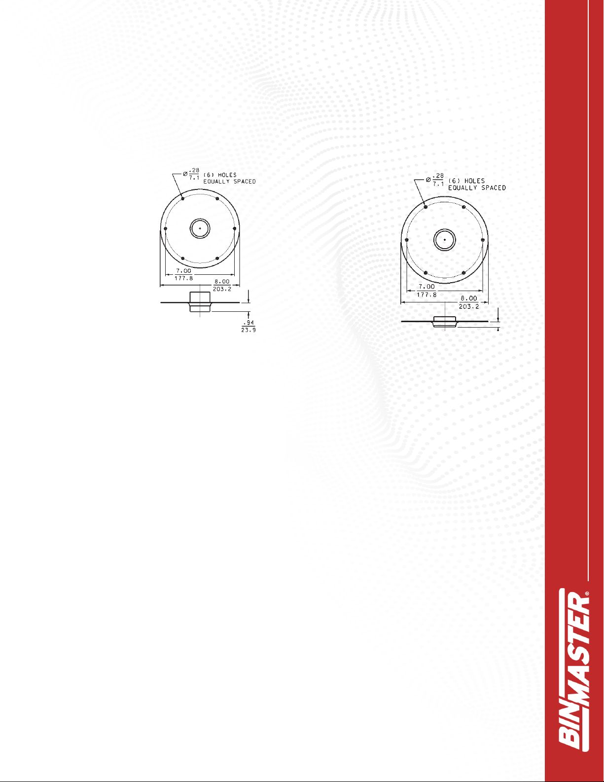
Mounting Plates
Mounting plates allow installing a completely assembled rotary through the vessel side or top.
The mounting plates have 6 bolt holes equally spaced on a 7-inch bolt circle. Mounting plates are
available with 1.25” or 1.5” NPT half or full couplings dependent on the process tting size of the
rotary.
Half couplings are used for all side mount installations or if top mounting a rotary without using a
guard pipe.
Full couplings are for top-of-vessel installations when using shaft extensions and shaft guard
pipes. Do NOT use full couplings for side mounting. The void on the process side of a full coupling
could allow material to pack in the void and interfere with rotation of the rotary shaft.
Cut a hole in the vessel wall large enough for the paddle to t through. Place the gasket between
the mounting plate and the vessel and install 6 mounting bolts through the mounting holes to
secure the plate to the vessel.
Mounting without Mounting Plates
Select a coupling or tri-clover tting that matches the size of the process tting on the rotary. Cut a
hole in the vessel big enough to t the coupling through the vessel wall. Weld the coupling to the
vessel wall to seal out moisture and dust.
925-0417 REV A 6 0124
BMRX-300 DC Rotary Level Indicator
For use with all rotary
level controls. Full
coupling is used for
top-of-bin installa-
tions where shaft
extensions and shaft
guards are used.
For use with all
rotary level
controls. Half
coupling is used
primarily for side of
bin installations.
Figure 4 Figure 5
Half CouplingFull Coupling
Mounting Plates
Mounting plates are needed when a completely assembled rotary is mounted on the bin wall
from the outside. Cut a 5-1/2” hole in the bin. Drill six bolt holes around the hole to match the
mounting plate. Bolt the plate, with the unit attached, into place. Mounting plates are available
in carbon or stainless steel

925-0417 REV A 7 0124
BMRX-300 DC Rotary Level Indicator
2.2 Locating and Mounting
SIDE MOUNT
1. Determine location and cut hole inside of bin to t outside diameter of 1-1/4” pipe
coupling (1.950").
2. Weld on half of standard 1-1/4” pipe coupling to bin wall ush with inside of bin.
3. Insert hub into coupling and turn rotary so conduit entries are pointed down toward the
ground.
4. Screw paddle into place and replace lock pin.
5. Shaft and paddle should be shielded in low level mounting to protect from material ow.
6. For side mounting, a solid coupler is recommended.
Figure 1

925-0417 REV A 8 0124
BMRX-300 DC Rotary Level Indicator
Conduit Seal
When installing the rotary in environments where moisture or moist air may enter the unit
through the electrical conduit, the conduit openings should be sealed with an appropriate duct
seal compound or putty.
Mounting Orientation
To prevent moisture or humidity from entering the unit when mounted on the side of the bin,
the rotary MUST be mounted with the conduit entries facing down.
MOUNTING
Use the 1.70" ats provided on the process connection
for tightening the instrument into the mounting coupler or
mounting plate.
The enclosure can be rotated 360 degrees after the
process connection is tight. NOTE: For side mount
application, rotate enclosure conduit entries DOWN after
the process connection is tight. Note: Tighten/loosen only using the
1.70" ats provided on the process
connection.
Rotate enclosure conduit entries down
after process connection is tight.
1-1/4" pipe coupling or
mount plate welded or
bolted to bin
1-1/4" guard pipe
SS or galv.
1/4" pipe extension
threaded into
exible coupling
1/4" pipe coupling
To required
material level
3/4" NPT
conduit opening
Bin wall
Figure 2
TOP MOUNT
1. Determine mounting location and cut a hole in top of bin to
t outside diameter of 1-1/4” pipe coupling (1.950”).
2. Position coupling halfway into bin and weld to bin.
3. Turn rotary so conduit openings are in desired location.
4. Add 1/4” extension pipe of desired length with standard
1/4” coupling on bottom end.
5. Cut 1-1 /4” support pipe approximately 4” shorter than
overall length of 1/4” pipe shaft if used with exible
coupling.
6. Insert 1-1/4” pipe into coupling and tighten.
7. Insert paddle into 1/4” coupling and drill holes for lock pins.

925-0417 REV A 9 0124
BMRX-300 DC Rotary Level Indicator
2.3 Input Power and Field Wiring
The BMRX-300 operates at 115 VAC or 230 VAC supply voltages. Field wiring should
conform to all national and local electrical codes and codes of any other agency or
authority with jurisdiction over the installation. For power input, use wire sized and rated
for the maximum voltage and current according to equipment ratings with a temperature
rating of at least 70°C. For SPDT switch output, use wire sized and rated for the maximum
voltage and current for the application, up to 250 VAC 10A, and has a temperature rating
of at least 70°C. Installation must be done by qualied personnel.
NOTE: Open the screw terminals fully before inserting wiring.
BMRX-300 Wiring Input Power
Power input to BMRX-300 is connected to the POWER terminals labeled LINE L and N.
AC Models
On AC models, if one of the conductors is grounded, connect to thhe N terminal. Connect
the ungrounded conductor to the L terminal. If neither conductor is grounded, connect one
of the N terminal and the other to the L terminal.

925-0417 REV A 10 0124
BMRX-300 DC Rotary Level Indicator
2.4 Grounding
An equipment grounding connection (earth ground) to the rotary is required for safety.
Connect the ground conductor to the green grounding screw inside the enclosure.
Relay Status
Outputs Relay Power
1 1NC 7 NO 9 Neutral
2 1C 8 C 0 Line
3 1NO
4 2NO
5 2C
6 2NC
3.0 DPDT Relay
The DPDT relay utilizes a Fail Safe selector DIP switch. There are two positions for the
switch, High (H) and Low (L). A Fail Safe condition means the DPDT relay contact positions
are set so in the event of a power failure the relay will be de-energized and the contacts will
indicate a condition that is deemed safe for the application.
3.1 Fail Safe High
Fail Safe High means that the relay will be energized when the paddle is rotating (uncovered)
and will de-energize when the paddle is covered. In this mode, a power failure will cause the
relay contacts to indicate that the paddle is covered, whether it is or not.
3.2 Fail Safe Low
Fail Safe Low means that the relay will be de-energized when the paddle is rotating
(uncovered) and will energize when the probe is covered. In this mode, a power failure
will cause the relay contacts to indicate that the paddle is uncovered, whether it is or not.

925-0417 REV A 11 0124
BMRX-300 DC Rotary Level Indicator
3.3 Status LED Indication
The visual LED array indicates the status of the sensor. The three statuses are:
Paddle rotating Rotating GREEN LEDs
Paddle covered Solid RED LEDs
Instrument fault Flashing YELLOW LEDs
Loss of input power LEDs OFF
3.4 Status Relay Output
The Status Relay indicates the status of the BMRX-300. There are two modes of operation for
the Status Relay, Normal (N) and Pulse (P). The mode for the Status Relay is selected by the
#2 position of the DIP switch.
In the Normal (N) position, the Status Relay is energized (C and NO closed) when the
BMRX-300 is operating correctly. In this mode, shaft rotation is detected or there is a
covered indication of paddle.
If the shaft is not rotating and the "covered switch" is not indicating covers, then the BMRX-
300 will go into a Fault condition (C and NO open). A Fault condition is indicated by both the
Status Relay and the DPDT output relay de-energizing, and the visual LED array pulsing
YELLOW.
3.5 Time Delay
The BMRX-300 has selectable time delay for the DPDT relay contacts. This time delay can
be selected for switching from an uncovered to a covered condition or for switching between
a covered to an uncovered condition or both.

925-0417 REV A 12 0124
BMRX-300 DC Rotary Level Indicator
The time delay is selected by time delay DIP switches #3 and #4. Switch 3 is for selecting
a time delay for going from an uncovered to a covered condition. Switch 4 is for select-
ing a time delay for going from a covered to an uncovered condition. When both switches
are OFF, there is no time delay. When the switch is ON, there will be a time delay for that
condition.
By default, the time delay is set to 5 seconds for both switches. This time delay can be
changed by using the SETUP push button switch on the circuit board. The Delay Time can
be set for each switch independently or for both together if the same delay time is desired
for both "delay on covered" and "delay on uncovered". The maximum time delay that can
be programmed is 28 seconds. Follow the procedured below to change the delay time.
3.6 Changing the Delay Time
Step 1. Select the switch for the delay time that you want to change by placing it in the ON
position. Switch 3 is for “Delay on Covered”. Switch 4 is for “Delay on Uncovered”. The
new delay time will be set for switch or switches in the ON position. At least one of the
delay switches must be ON in order to enter the programming mode.
Step 2. Press and hold the SETUP switch for three seconds to initiate the programming
mode. The LED will ash fast for these three seconds to indicate entry of the program
mode. Releasing the SETUP switch during this initial three second period will abort the
program mode and leave the delay times unchanged.
Step 3. After the three seconds has passed, continue holding the SETUP switch for the
desired amount of delay time in seconds. The LED stops ashing fast and will blink every
second for indication of the delay time so far. Each one second ash is one second of
delay time.
Step 4. After the desired amount of delay has passed, one second for each blink, release
the SETUP switch and the delay time will be set for the delay switches that are in the ON
position. You may enter up to 28 seconds. Holding the SETUP switch longer than this will
have no eect and limit the delay to 28 seconds.

925-0417 REV A 13 0124
BMRX-300 DC Rotary Level Indicator
4.0 WARRANTY AND CUSTOMER SERVICE
4.1 Limited Warranty
LIMITED PRODUCT WARRANTY. Products manufactured by Seller are warranted for a pe-
riod of one (1) year from date of shipment against defective materials and workmanship (the
“Warranty Period”). SELLER MAKES NO OTHER WARRANTY, EXPRESS OR
IMPLIED, AND ANY WARRANTY OF MERCHANTABILITY OR FITNESS FOR A
PARTICULAR PURPOSE IS HEREBY DISCLAIMED AND EXCLUDED.
This limited warranty does not extend to labor charges or other costs related to the removal
and/or replacement of defective products or services. Any technical advice or services
furnished by Seller with respect to the products is given without charge, and Seller assumes
no obligation or liability for the advice given or results obtained, all such advice being given
and accepted at Buyer's sole risk and expense. If the products are being acquired for resale,
Buyer will make, in connection with any such resale, only those warranties contained herein
and will indemnify Seller and its ocers, directors, agents, employees, aliates, successors,
and assigns against any claims, causes of actions and judgments which arise from any
representations, warranties, or agreements made by or entered into by Buyer, other than
those contained herein.
WARRANTY EXCLUSIONS. Notwithstanding Seller’s Limited Product Warranty, products
that have been or are (1) damaged by accident, corrosion, the elements, abuse, misuse,
misapplication, vandalism, negligence, improper transportation, handling, storage, use or lack
of proper and reasonable maintenance, (2) repaired or altered by anyone other than Seller or
its authorized service providers, (3) modied or altered without Seller’s written authorization,
or (4) specially manufactured by Seller as per specications provided by Buyer, are expressly
excluded from Seller’s Limited Product Warranty.
4.2 Customer Service
BinMaster's toll-free Customer Service phone number is 1-800-278-4241. Call the
Technical Service Department for support Monday through Friday from 8:00 AM to 5:00 PM
Central Time. International customers call 1-402-434-9102 or techsupport@binmaster.com.
5.0 DISPOSAL
This product contains recyclable materials and electronics that can be easily separated and
recycled by specialized recycling companies. Consult local authorities for proper disposal
locations.

925-0417 REV A 14 0124
BMRX-300 DC Rotary Level Indicator
925-0417 0124
BinMaster: Division of Garner Industries LLC
7201 N. 98th St.
Lincoln, NE 68507
402-434-9102
info@binmaster.com | www.binmaster.com
Table of contents
Other Bin Master Measuring Instrument manuals

Bin Master
Bin Master BMRX-100 User manual

Bin Master
Bin Master CNCR-210 User manual

Bin Master
Bin Master NCR-80 User manual

Bin Master
Bin Master GWR-3000 User manual

Bin Master
Bin Master MAXIMA+ Series User manual

Bin Master
Bin Master BMRX Series User manual

Bin Master
Bin Master CNCR-110 User manual

Bin Master
Bin Master DPM-400 User manual

Bin Master
Bin Master DPM-500 User manual

Bin Master
Bin Master 1000 User manual


