Bin Master CNCR-210 User manual
CNCR-210 • Two-wire 4
-
20 1
Operating Instructions
Radar sensor for continuous level measurement
CNCR-210
Two-wire 4
-
20 mA
Document ID: 925-0395 Rev B

CNCR-210 • Two-wire 4
-
20 2
Contents
1 About this document ............................................................................................................. 3
2 For your safety ....................................................................................................................... 3
2.1 Authorized personnel ....................................................................................................... 3
2.2 Appropriate use................................................................................................................ 3
2.3 Warning about incorrect use ............................................................................................ 4
3 Product description ............................................................................................................... 4
3.1Conguration.................................................................................................................... 4
3.2 Principle of operation ....................................................................................................... 5
3.3 Adjustment ....................................................................................................................... 5
4 Mounting................................................................................................................................. 6
4.1 General instructions ......................................................................................................... 6
4.2 Mounting versions............................................................................................................ 6
5 Connecting to power supply................................................................................................. 9
5.1 Preparing the connection ................................................................................................. 9
5.2 Connecting..................................................................................................................... 10
5.3 Wiring plan ..................................................................................................................... 11
6 Setup with smartphone/tablet (Bluetooth) ........................................................................ 11
6.1 Preparations................................................................................................................... 11
6.2 Connecting..................................................................................................................... 12
6.3 Parameter adjustment.................................................................................................... 13
7 Menu overview ..................................................................................................................... 14
8 Diagnostics and servicing .................................................................................................. 15
8.1 Maintenance .................................................................................................................. 15
8.2 Status messages ........................................................................................................... 15
9 Removal ................................................................................................................................ 17
10 Certicates and approvals .................................................................................................. 17
10.1 Radio licenses.............................................................................................................. 17
11 Supplement .......................................................................................................................... 17
11.1 Technical data .............................................................................................................. 17
11.2 Dimensions................................................................................................................... 19
CNCR-210 • Two-wire 4
-
20 3
Information, note, tip: This symbol indicates helpful additional
information and tips.
Note: This symbol indicates notes to prevent failures, malfunctions,
damage to devices or facility.
Caution: Non-observance may result in personal injury.
Warning: Non-observance may result in serious or fatal personal injury.
Danger: Non-observance of the information marked with this symbol
results in serious or fatal personal injury.
Ex applications
This symbol indicates special instructions for Ex applications.
List
The dot set in front indicates a list with no implied sequence.
Sequence of actions
Numbers set in front indicate successive steps in a procedure.
Battery disposal
This symbol indicates special information about the disposal of
batteries and accumulators.
1 About this document
2 For your safety
2.1 Authorized personnel
Alloperationsdescribedinthisdocumentationmustbecarriedoutonlybytrained,qualied
personnel authorized by the plant operator. Required personal protective equipment must always
be worn when working on or with the device.
2.2 Appropriate use
CNCR-210 is a sensor for continuous level measurement. Operational reliability is ensured only if
theinstrumentisproperlyusedaccordingtothespecicationsintheoperatinginstructions.

CNCR-210 • Two-wire 4
-
20 4
Safety instructions for Ex areas
TakenoteoftheExspecicsafetyinstructionsforExapplications.Theseinstructions
are attached as documents to each instrument with Ex approval and are part of the
operating instructions.
2.3 Warning about incorrect use
Inappropriateorincorrectuseofthisproductcanresultinapplication-specichazards,e.g.vessel
overllbyincorrectmountingoradjustment.Damagetopropertyandpersonsorenvironmental
contamination can result.
3 Product Description
3.1 Conguration
Fig. 1: Components of CNCR-210
1 Radar antenna
2 Processtting
3 Process seal
4 Electronics housing
5 Ventilation/pressure compensation
CNCR-210 • Two-wire 4
-
20 5
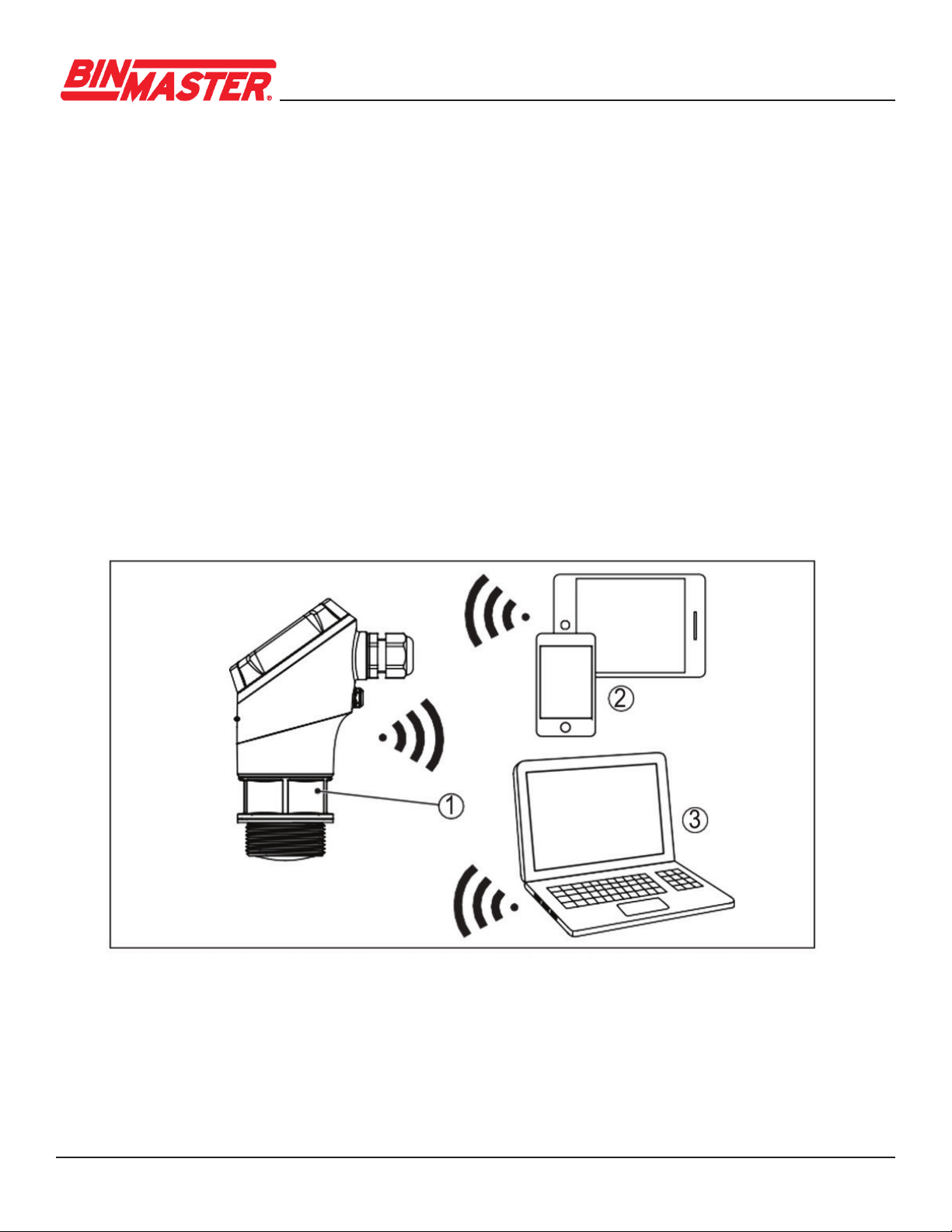
3.3 Adjustment
Devices with integrated Bluetooth module can be adjusted wirelessly via software adjustment tools:
• Smartphone/tablet (iOS or Android operating system)
• PC/notebook with Bluetooth USB adapter (Windows operating system)
Fig. 2: Wireless connection to standard operating devices with integrated Bluetooth LE
1 Sensor
2 Smartphone/Tablet
3 PC/Notebook
3.2 Principle of operation
CNCR-210 is a radar sensor for continuous level measurement. It is suitable for liquids and sol-
ids in practically all industries.
The instrument emits a continuous, frequency-modulated radar signal from its antenna. The emit-
tedsignalisreectedbythematerialandreceivedbytheantennaasanechowithamodied
frequency. The frequency change is proportional to the distance to the material.
CNCR-210 • Two-wire 4
-
20 6
4.2 Mounting
The radar emits pulses of electromagmetic waves which are polarized. By adjusting the rotation of
the instrument the polarization can be changed to reduce false echoes.
The narrow portion of the radar signal is in the middle of the conduit entry on the instrument. This
should be pointed towards the center of the vessel or any obstacle that may cause any unwanted
reectionstominimizefalseechos,forexample,thesidewallorvesselstructure.
4 Mounting
4.1 General instructions
The instrument is suitable for standard and extended ambient conditions according to DIN/EN/IEC/
ANSI/ISA/UL/CSA 61010-1. It can be used indoors as well as outdoors.
Protect your instrument against moisture ingress through the following measures:
• Use a suitable connection cable
•Tightenthecableglandorplugconnectorrmly
• Face the cable connection or conduit entry downward, never upward
This applies mainly to outdoor installations, in areas where high humidity is expected (e.g. through
cleaning processes) or on cooled or heated vessels.
Fig. 3: Polarization position
Cable / conduit entry
Note:
Whenthehousingisrotated,thedirectionofpolarizationchangesandhencetheinuenceofthefalse
echo on the measured value. Please keep this in mind when mounting or making changes later.
CNCR-210 • Two-wire 4
-
20 7
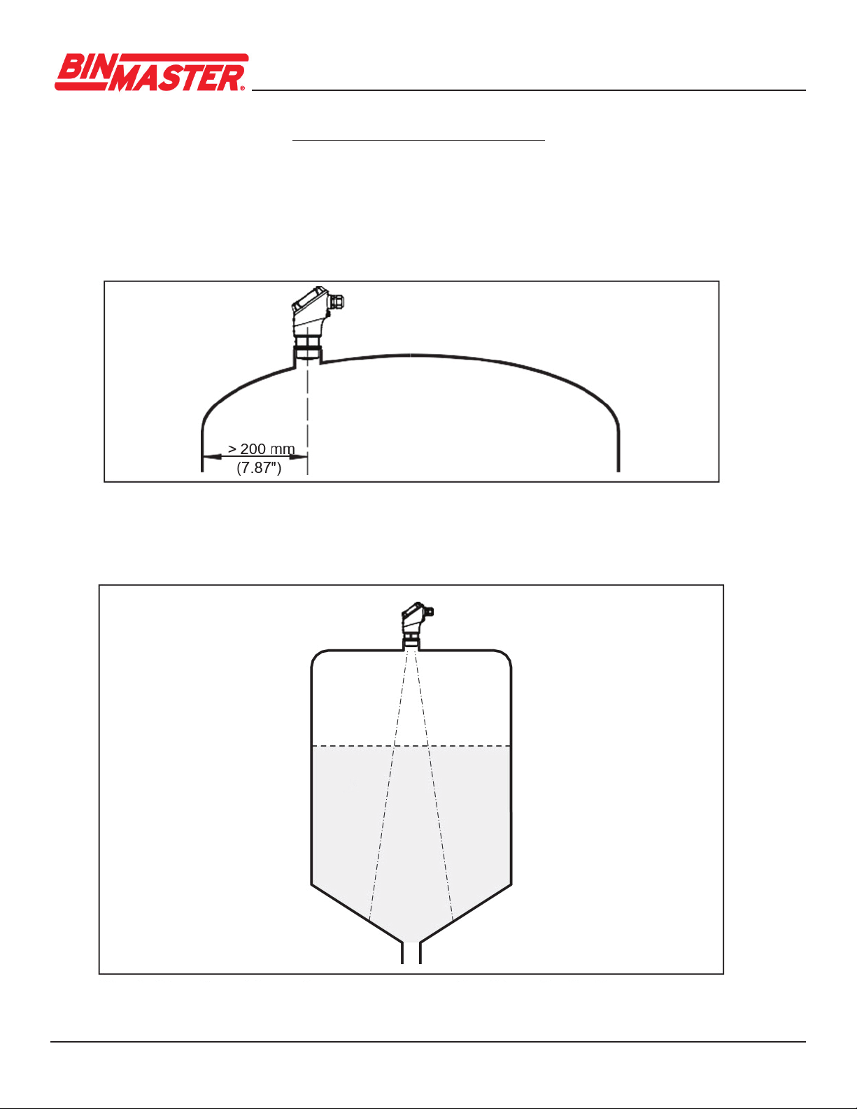
In vessels with cone bottoms, the sensor can be mounted in the center of the vessel to mea-
sure material down to the outlet.
When mounting the sensor, distance it at least 200 mm (7.874 in) from the vessel wall. If the sensor
is installed in the center of dished or round vessel tops, multiple echoes can arise. However, these
can be suppressed by a false signal suppression (see chapter “Setup”).
If you cannot maintain this distance, you should carry out a false signal suppression during initial
setup. This applies particularly if buildup on the vessel wall is expected. If this is the case, we
recommend repeating the false signal suppression later with the additional buildup.
Fig. 5: Mounting the radar sensor with conical bottom
Fig. 4: Mounting the radar sensor on round vessel tops

CNCR-210 • Two-wire 4
-
20 8
Donotmounttheinstrumentinorabovethellstream.Makesurethatitispointedtowardsthe
materialsurface,notthellstream.
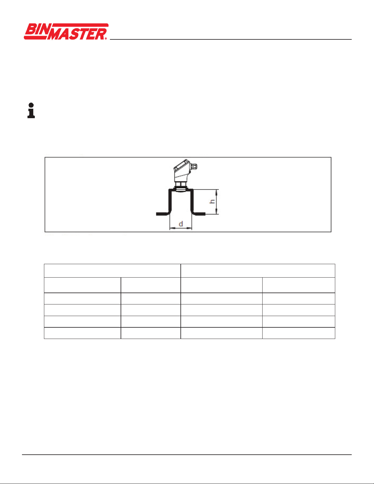
For socket or stand pipe mount, the pipe should be as short as possible and its bottom end
roundedtoreducefalsereectionsfromtheendofthepipe.
When using a threaded coupling, the antenna end should protrude at least 5 mm (0.2 in) out
of the coupling.
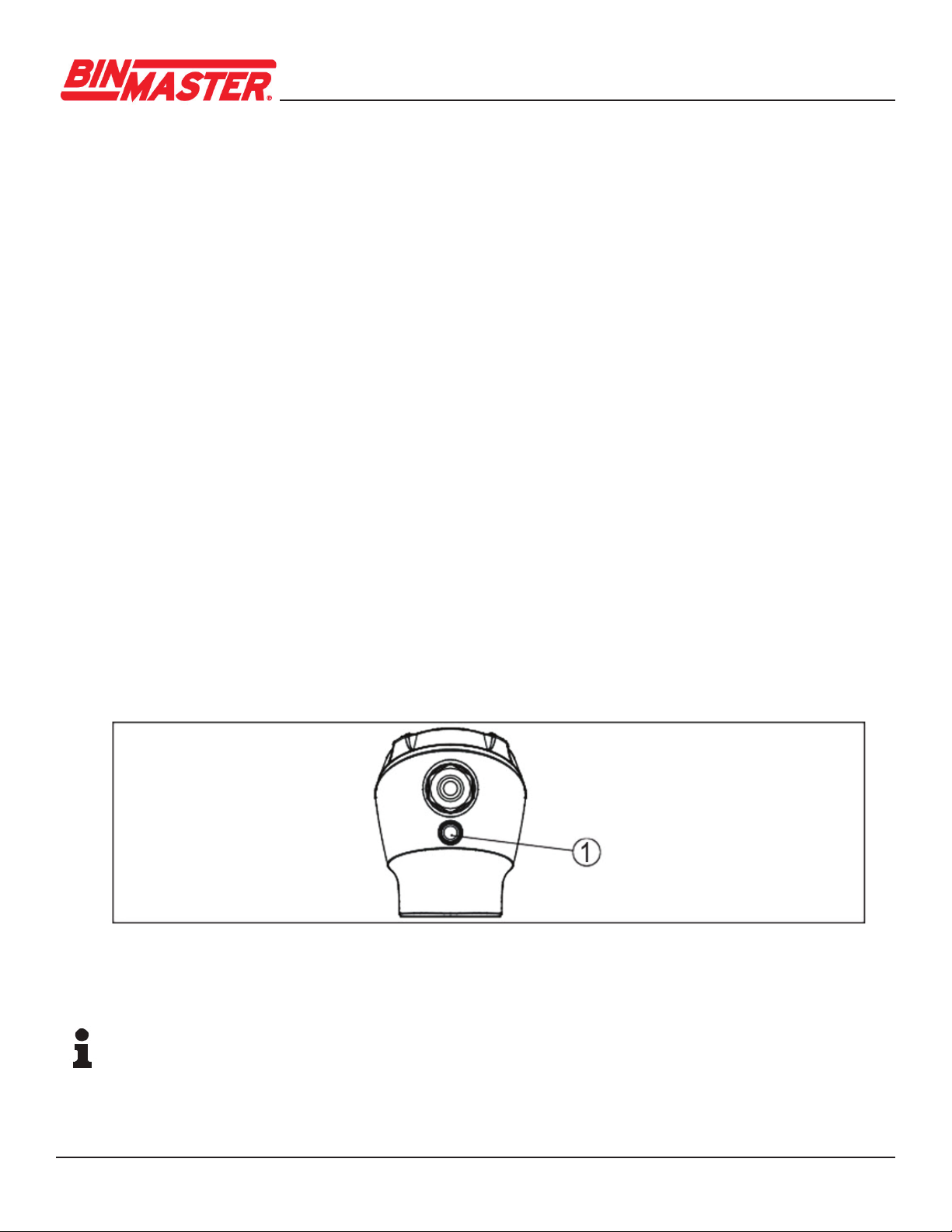
Fig. 6: Reference plane
1 Reference plane
Fig.7:Mountingtheradarsensorwithinowingmaterial
The lower side of the radar antenna is the reference plane for the min./max. adjustment, see
following diagram:
CNCR-210 • Two-wire 4
-
20 9
Socket diameter d Socket length h
40 mm 1½” ≤150mm ≤5.9in
50 mm 2” ≤200mm ≤7.9in
80 mm 3” ≤300mm ≤11.8in
100 mm 4” ≤400mm ≤15.8in
150 mm 6” ≤600mm ≤23.6in
Ifthereectivepropertiesofthematerialaregood,youcanmounttheCNCR-210onsockets
or stand pipes longer than the antenna. The pipe end should be smooth, burr-free and the end
rounded.
Note:
When mounting on longer sockets, we recommend carrying out a false signal suppression after
install (see chapter “Parameter adjustment”).
Recommended values for socket or stand pipe lengths and heights are in the following table. The
values come from typical applications.
Fig. 8: Mounting the radar sensor with stand pipes
5 Connecting to power supply
5.1 Preparing the connection
•Electricalconnectionshouldbecompletedbytrained,qualiedpersonnelauthorizedby
the plant operator.
• If overvoltage surges are expected, overvoltage arresters should be installed.
CNCR-210 • Two-wire 4
-
20 10
Warning:
Only connect or disconnect in de-energized state.
Note:
Power the instrument via an energy-limited circuit (power max. 100 W) according to IEC 61010-1,
e.g.
• Class 2 power supply unit (acc. to UL1310)
• SELV power supply unit (safety extra-low voltage) with suitable internal or external limitation
of the output current
UseroundcabletoensureeectivesealingofthecableglandtotheappropriateIPratingand
checkthecablediameterversusthecableglandbeforewiringforpropert.
The instrument is connected with standard two-wire cable.
If electromagnetic interference is expected which is above the test values of EN 61326-1 for
industrial areas, shielded cable should be used.
Note:
If the temperatures are too high, the cable insulation can be damaged.
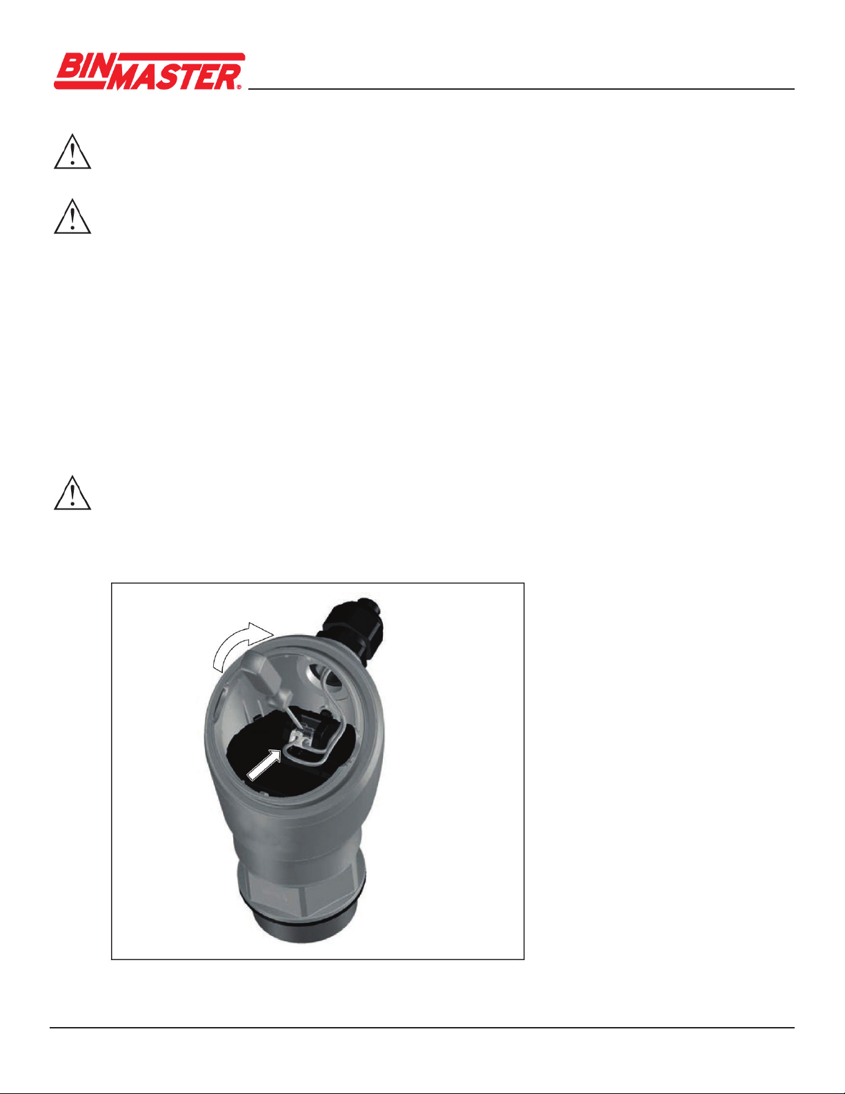
5.2 Connecting
Fig. 9: Connection

CNCR-210 • Two-wire 4
-
20 11
5.3 Wiring plan
Connect the instrument as described in the following wiring plan.
Fig. 10: Connection compartment CNCR-210
1 Voltage supply +24 VDC, signal output
6 Setup with smartphone/tablet (Bluetooth)
6.1 Preparations
Make sure that your smartphone/tablet meets the following system requirements:
• Operating system: iOS 8 or newer
• Operating system: Android 5.1 or newer
• Bluetooth 4.0 LE or newer
DownloadtheWirelessDeviceConguratorappfromthe“AppleAppStore”or“GooglePlay
Store” to your smartphone or tablet. To enable the Bluetooth software enter the BinMaster
company ID code BMYQXZ.
CNCR-210 • Two-wire 4
-
20 12
6.2 Connecting
Start the adjustment app and select the function “Setup”. The smartphone/tablet searches
automatically for Bluetooth-capable instruments in the area.
The message “Connecting …” is displayed.
The devices found are listed and the search is automatically continued.
Select the requested instrument in the device list.
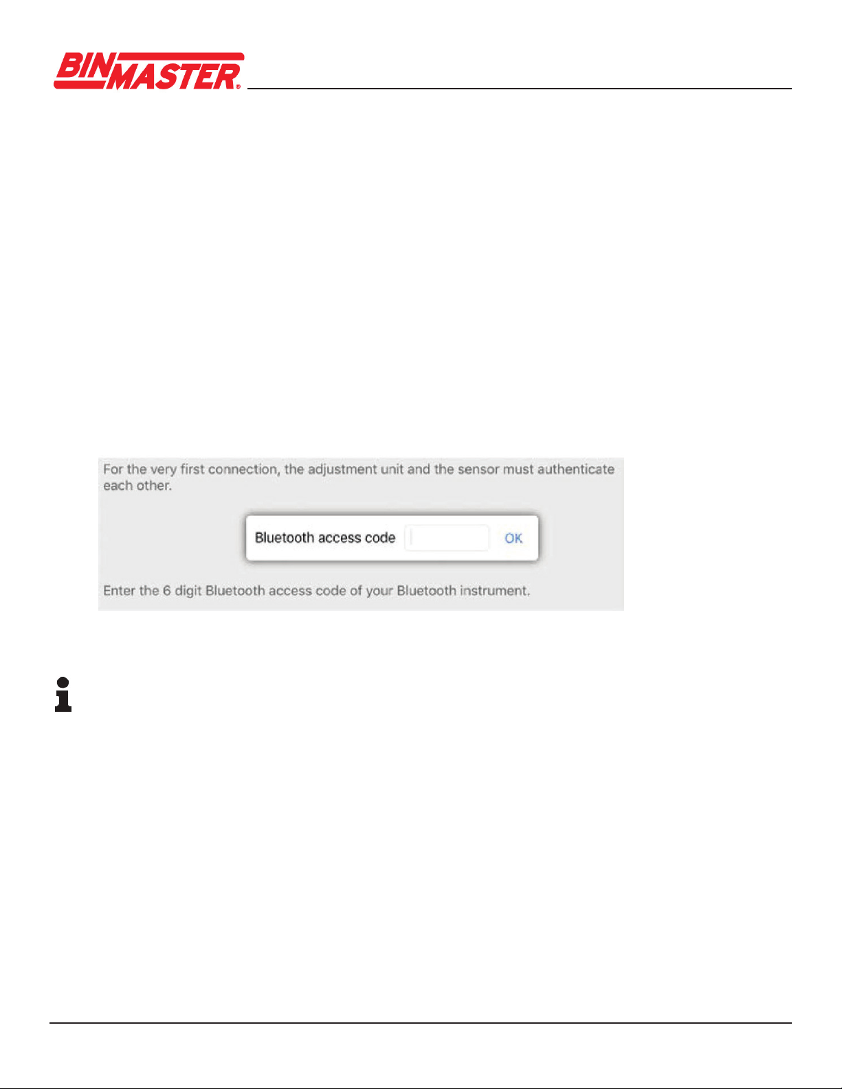
Whenestablishingtheconnectionforthersttime,theoperatingtoolandthesensormust
authenticateeachother.Aftertherstcorrectauthentication,eachsubsequentconnectionis
made without a new authentication query.
Forauthentication,enterthe6-digitBluetoothaccesscodeinthenextmenuwindow.Youcannd
the code on the outside of the device housing and on the setup information sheet in the device
packaging.
Note:
If an incorrect code is entered, the code can only be entered again after a delay time and the delay
gets longer after each incorrect entry.
The message “Waiting for authentication” is displayed on the smartphone/tablet.
After connection, the sensor adjustment menu is displayed on the smartphone/tablet.
If the Bluetooth connection is interrupted, e.g. due to a too large distance between the two devices,
this is displayed on the smartphone/tablet. The message disappears when the connection is restored.
Parameter adjustment of the device is only possible if the parameter protection is deactivated, which
is default. Parameter protection can be activated later if desired.
Fig. 11: Enter Bluetooth access code
CNCR-210 • Two-wire 4
-
20 13
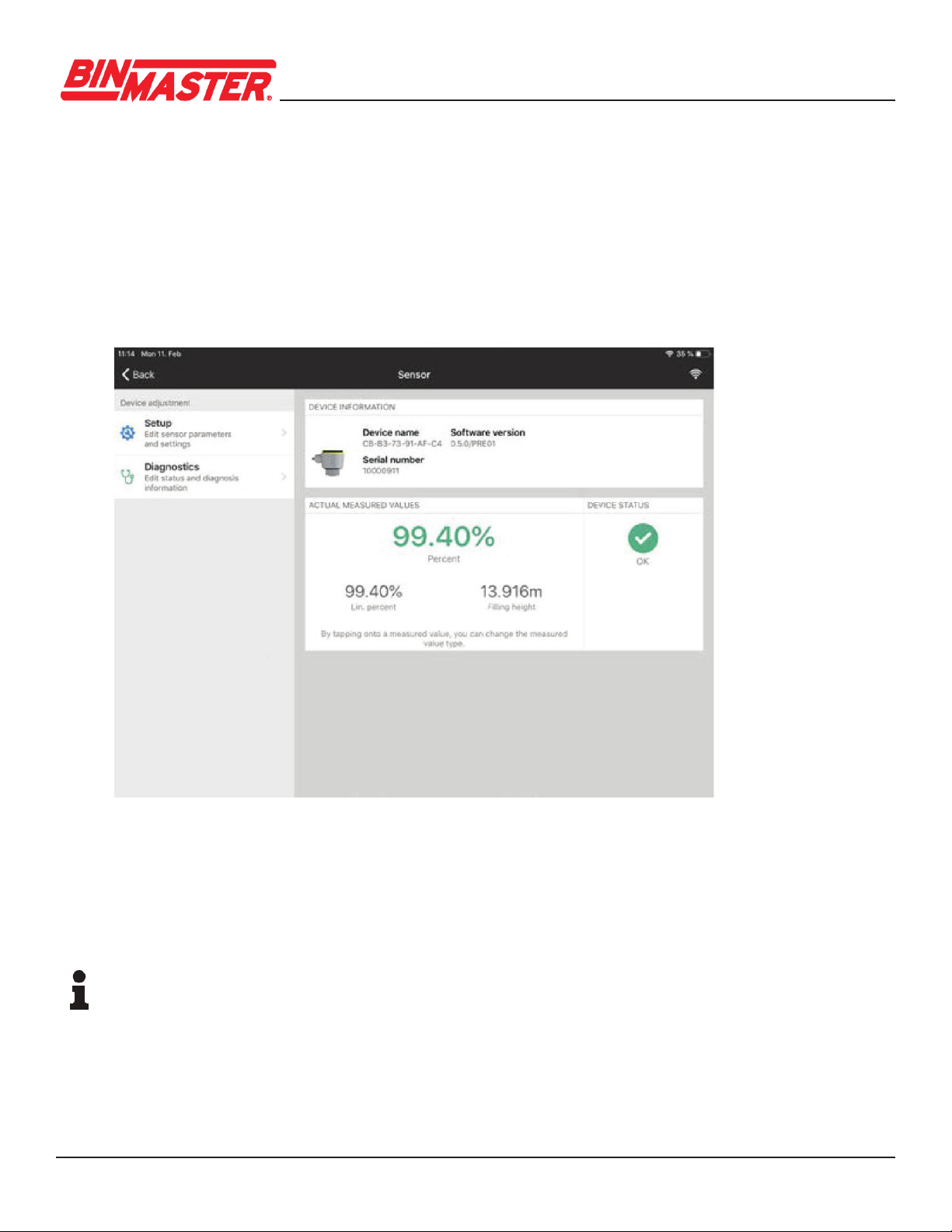
6.3 Parameter adjustment
The sensor adjustment menu is divided into two areas, which are arranged next to each other or
one below the other, depending on the smartphone/tablet.
• Navigation section
• Menu item display
The selected menu item can be recognized by the color change.
Entertherequestedparametersandconrmviathekeyboardortheeditingeld.Thesettingsare
then active in the sensor.
Close the app to terminate connection.
Note
IftheCNCRfailstoconnecttotheWirelessDeviceCongurationApp(WDCA)viaBluetooth,
close the (WDCA), power cycle the CNCR and attempt to reconnect.
If further action is required, power cycle the Bluetooth on your device, and repeat the steps above.
Fig. 12: Example of an app view - Setup sensor adjustment
CNCR-210 • Two-wire 4
-
20 14
Menu item Selection Default settings
False signal suppression False signal suppression 0 m
Sounded distance to the material 0 m
Reset Delivery status, basic settings -
Menu item Selection Default settings
Measurement loop name Alphanumeric characters Sensor
Medium Liquid
Bulk solid
Liquid
Application liquid
Storage tank, agitator tank, dosing tank, pumping
station/pumpshaft,rainoverowbasin,tank/collection
basin, plastic tank (measurement through tank top),
mobile plastic tank (IBC), level measurement in waters,
owmeasurementume/over-ow,demonstration
Storage tank
Application bulk solid Silo (slim and high), bunker (large
volume), stockpile (point measurement/
proledetection),crusher,demonstration
Silo
(slender and high)
Units Distance unit of the device
Temperature unit of the instrument
Distance in ft.
Temperature in °F
Adjustment Max. adjustment (distance A) - 20mA (100%)
Min. adjustment (distance B) - 4mA (0%)
Distance from sensor
Max. adjustment 0.0 m
Min. adjustment 8.0 m
Menu item Selection Default settings
Damping Integration time 0 s
Current output Output characteristics 4 to 20 mA = 0% to 100%
Current range Min. current 4 mA and
max. current 20.5 mA
Reaction when malfunctions occur Failure mode < 3.6 mA
Linearization Linearization type Linear
Scaling Scaling size
Scaling unit
Scaling format
0% correspond to 0 l
100% correspond
to 100 l
Display Menu language
Displayed value
Backlight
English
Distance
On
Access protection Bluetooth access code -
Parameter Protection Deactivated
Menu item Selection Default settings
Status Sensor status
Measured value status
Status output
Status additional measured values
-
Echo curve Indication of echo curve -
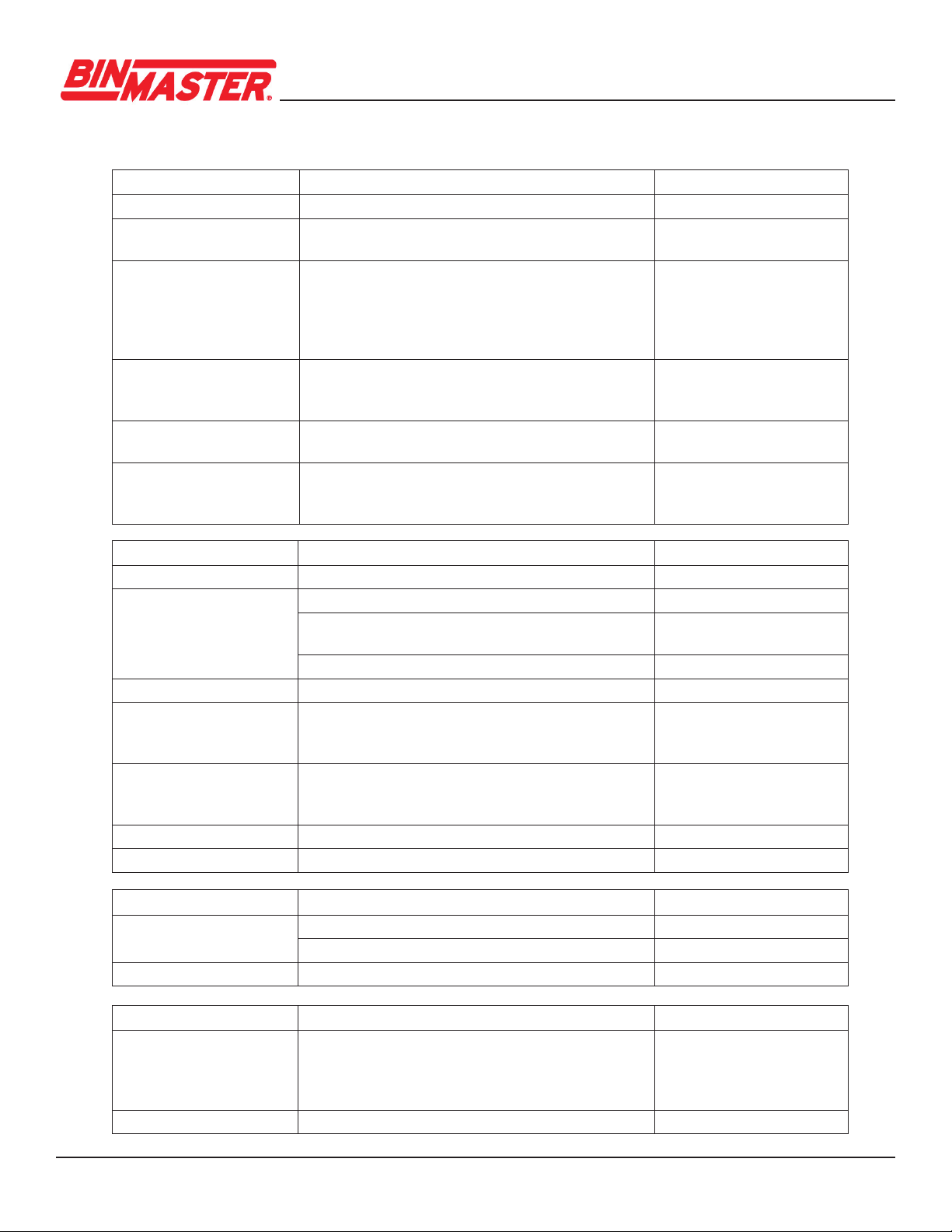
7 Menu overview

CNCR-210 • Two-wire 4
-
20 15
Code
Text message Cause Rectication
F013
No measured value
available
No measured value in the boot
up phase or during operation
Check or correct installation and/
or parameter settings
Clean the antenna system
F017
Adjustment span
too small
Adjustment not within
specication
Change adjustment according to the
limitvalues(dierencebetweenmin.
andmax.≥10mm)
F025
Error in the
linearization table
Linearization values are not
continuously rising, for example
illogical value pairs
Check linearization table
Delete table/Create new
F036
No operable software
Checksum error if software update
failed or aborted
Repeat software update
Send instrument in for repair
F040
Error in the electronics
Limit value exceeded in signal
processing
Hardware error
Restart instrument
Send instrument in for repair
F080
General software error
General software error Restart instrument
8 Diagnostics and servicing
8.1 Maintenance
If the device is used properly, no special maintenance is required in normal operation.
Insomeapplications,buildupontheantennasystemcaninuencethemeasurement.
Depending on the sensor and application, be careful to avoid heavy soiling of the antenna
system. If necessary, clean the antenna system periodically.
8.2 Status messages
The status messages are divided into the following categories:
• Failure
• Function check
•Outofspecication
• Maintenance required
Failure
CNCR-210 • Two-wire 4
-
20 16
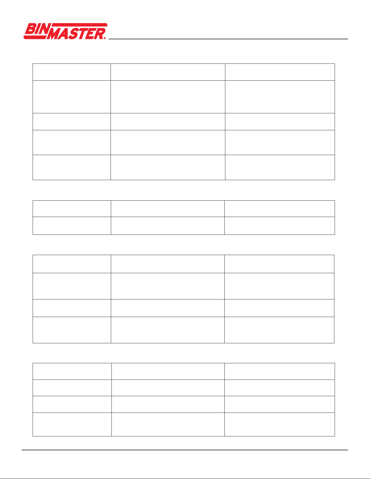
Code
Text message Cause Rectication
S600
Impermissible electronics
temperature
Temperature of the electronics out of
speciedrange
Check ambient temperature
Insulate electronics
S601
Overlling
Dangerofvesseloverlling Makesurethatthereisnofurtherlling
Check level in the vessel
S603
Impermissible
operating voltage
Terminal voltage too low Check terminal voltage,
increase operating voltage
Code
Text message Cause Rectication
C700
Simulation active
A simulation is active Finish simulation
Wait for the automatic end after 60 mins.
Code
Text message Cause Rectication
F105
Determine
measured value
The instrument is still in the boot up
phase, the measured value could not
yet be determined
Wait for the end of the boot up phase
Duration up to 3 minutes depending on
the measurement environment and
parameter settings
F260
Error in the calibration
Checksum error in the calibration values
Error in the EEPROM
Send instrument for repair
F261
Error in the instrument
settings
Error during setup
False signal suppression faulty
Error when carrying out a reset
Repeat setup
Reset instrument
F265
Measurement function
disturbed
Program sequence of the
measuring function disturbed
Device restarts automatically
Code
Text message Cause Rectication
M500
Error in the delivery status
M501
Error in the delivery status
M504
Error at a device interface
Hardware defect Check connections
Replace the electronics
Send instrument in for repair
Failure
Function check
Out of specication
Maintenance

CNCR-210 • Two-wire 4
-
20 17
9 Removal
The device is made of recyclable materials that can be disposed of by specialty recycling companies.
Observe the applicable local regulations for proper disposal.
10 Certicates and approvals
10.1 Radio licenses
Radar
The device has been tested and approved in accordance with the current edition of the applicable
country-specicnormsorstandards.
Bluetooth
The Bluetooth radio module in the device has been tested and approved according to the current edition
oftheapplicablecountry-specicnormsorstandards.
11 Supplement
11.1 Technical data
Note for approved instruments
The technical data in the respective safety instructions which are included are valid for approved
instruments(e.g.withExapproval).Thesedatacandierfromthedatalistedherein,forexample
regarding the process conditions or the voltage supply.
Code
Text message Cause Rectication
M505
No echo available
Sensor does not detect an echo
during operation
Antenna dirty or defective
Clean the antenna
Use a more suitable antenna/sensor
Remove possible false echoes
Optimize sensor position and orientation
M507
Error in the instrument
settings
Error during setup
Error when carrying out a reset
False signal suppression faulty
Reset instrument and repeat setup
M508
Data error in program
memory Bluetooth controller
M509
Software update
M510
No communication with
the sensor

CNCR-210 • Two-wire 4
-
20 18
Fig. 13: Data of the input variable
1 Reference plane
2 Measured variable, max. measuring range
Materials and weights
Materials, wetted parts
–Antenna,processtting PVDF
– Process seal FKM
Materials, non-wetted parts
– Housing Plastic PBT (Polyester)
– Housing seals O-rings (silicone)
– Cable gland PA
– Sealing, cable gland NBR
– Blind plug, cable gland PA
– Weight 0.7 kg (1.543 lbs)
Torques
Max. torque mounting boss 7 Nm (5.163 lbf ft)
Max. torque for NPT cable glands and conduit tubes 10 Nm (7.376 lbf ft)
Input variable
Measured variable
The measurement range is the distance between the
antenna face of the sensor and the material surface.
The antenna face is also the reference plane for
the measurement.
Max. measuring range4) 8 m (26.25 ft)
Recommended measuring range5) up to 5 m (16.4 ft)

CNCR-210 • Two-wire 4
-
20 19
Output
Output signal 4 to 20 mA
Range of the output signal 3.8 to 20.5 mA (default setting)
Signalresolution 0.3μA
Resolution, digital 1 mm (0.039 in)
Faultsignal,currentoutput(adjustable) ≤3.6mA,>=21mA,lastvalidmeasuredvalue
Max. output current 22 mA
Load See load resistance under Power supply
Startingcurrent ≤3.6mA;≤10mAfor5msafterswitchingon
Damping (63 % of the input variable), adjustable 0 to 999 s
Ambient conditions
Ambient temperature -40 to +60 °C (-40 to +140 °F)
Storage and transport temperature -40 to +80 °C (-40 to +176 °F)
Process conditions
Fortheprocessconditions,pleasealsonotethespecicationsontheprintedlabel.Thelowestvalue
(amount) always applies.
Process temperature -40 to +60 °C (-40 to +140 °F)
Process pressure -1 to 3 bar (-100 to 200 kPa/-14.5 to 43.51 psig)
Voltage supply
Operating voltage UB
– at 4 mA 12 to 35 V DC
– at 20 mA 9 to 35 V DC
Reverse voltage protection Integrated
Electrical protective measures
Altitude above sea level 5000 m (16404 ft)
Protection class III
Pollution degree 4
CNCR-210 • Two-wire 4
-
20 20
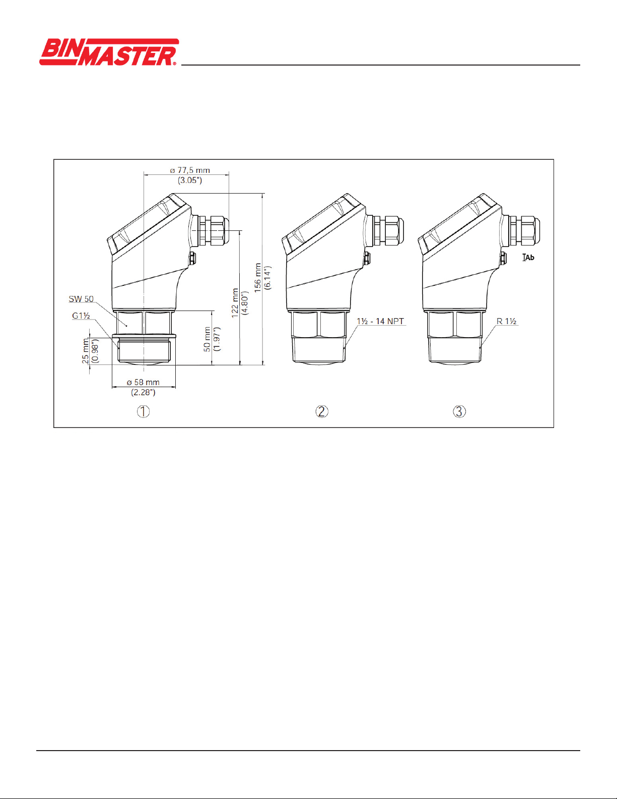
11.2 Dimensions
CNCR-210
Fig. 14: Dimensions CNCR-210
1 Thread G1½
2 Thread 1½ NPT
3 Thread R1½
Table of contents
Other Bin Master Measuring Instrument manuals

Bin Master
Bin Master SMARTBOB TS1 User manual

Bin Master
Bin Master 1000 User manual

Bin Master
Bin Master BMRX Series User manual

Bin Master
Bin Master BMRX-100 User manual

Bin Master
Bin Master DPM-500 User manual

Bin Master
Bin Master DPM-500 User manual

Bin Master
Bin Master GWR-2000 User manual

Bin Master
Bin Master PROCAP I Series User manual

Bin Master
Bin Master 3DLevelScanner-MVL User manual

Bin Master
Bin Master DPM-200 User manual


