BinTec elmeg CS290 User manual

Operating instructions
English
elmeg CS290
elmeg CS290-U
elmeg IP-S290plus
Operating instructions
English
elmeg CS290
elmeg CS290-U
elmeg IP-S290plus

Please note!
The system telephones and corresponding systems in this user guide use the following abbreviations:
System/PABX: Abbreviation:
elmegPABX elmeg PABX
elmegHybird300
elmegHybird600
elmeghybird. Alternativeconfigurationof the systemtelephones (seealso page67)
BintecTR200aw as PABX
BintecTR200bw as PABX
Declaration of Conformity and CE Mark
This device meets the requirements of R&TTE Directive 1999/5/EC:
»Directive 1999/5/EC of the European Parliament and of the Council of 9 March 1999 on radio equip-
mentandtelecommunicationsterminalequipmentandthemutual recognitionoftheir conformity«.
The Declaration of Conformity can be viewed at the following web address: http://www.bintec-el-
meg.com.
The crossed-out waste bin icon on the device indicates that the device must be disposed of separately from normal
household waste at the disposal sites provided at the end of its service life. You can find additional in-
formation on the individual return of used devices at www.bintec-elmeg.com.
© bintec elmeg GmbH - All rights reserved.
Thisdocumentmaynotbereproduced, in full or inpart,exceptwiththeapprovalof the publisher and with adetailed
reference to the source publication, irrespective of the nature and method or media (mechanical or electronic) by
which this is produced.
Functional descriptions of this documentation that relate to software products of other manufacturers are based on
thesoftware usedatthe time ofcreationor printing.Theproductor companynamesusedinthis documentationmay
in some cases be registered trademarks.

Table of contents
Telephone user interface................................................1
Description and installation .............................................3
elmeg CS410 ........................................................3
elmeg CS410-U.......................................................3
elmeg IP-S400 .......................................................3
Safety notices ......................................................4
Unpacking and positioning the system telephone .................................5
Connecting the system telephone (connector and receiver cord) ..........................5
Changing the label field ..................................................8
Pictograms .........................................................8
System telephone settings ..............................................10
Setting the display language...............................................10
Telephoning ......................................................13
Initiate a call .......................................................13
Accepting/rejecting a call ................................................14
Forwarding a call (Call Deflection)...........................................15
Suppressing the call number (anonymous call) ....................................15
Initiating a call with a fixed call number (MSN) ...................................15
Redialling .........................................................15
Switching the microphone on/off, loudspeaker ....................................17
Using the headset.....................................................17
Announcement ......................................................18
Automatic callback....................................................18
Intercept (MCID).....................................................19
Keypad and tone dialling (MFC dialling) .......................................20
Telephoning with several people ..........................................21
Call Waiting........................................................21
Hold for enquiry .....................................................21
Call forwarding (call transfer) .............................................21
Brokering .........................................................21
Conference ........................................................22
Operate system telephone ..............................................23
VIP memory .......................................................23
Caller history .......................................................23
SMS and UUS1 text messages..............................................25
Checking costs .....................................................30
Table of contents
I

Viewing and deleting costs ...............................................30
Set up tariff factor and denomination .........................................31
System telephony ...................................................32
Function keys .......................................................32
Function keys when connecting to a elmeg hybird or PABX ............................33
System menu on elmeg PABX with system telephony ..............................40
Configuring and setting the system telephone ..................................46
Advanced configuration .................................................46
Acoustic ..........................................................47
Display contrast .....................................................50
Configuration .....................................................51
elmeg IP-S400 configuration ..............................................55
Service..........................................................57
Index............................................................63
Options ..........................................................67
Quick Install Guide ..................................................71
Table of contents
II
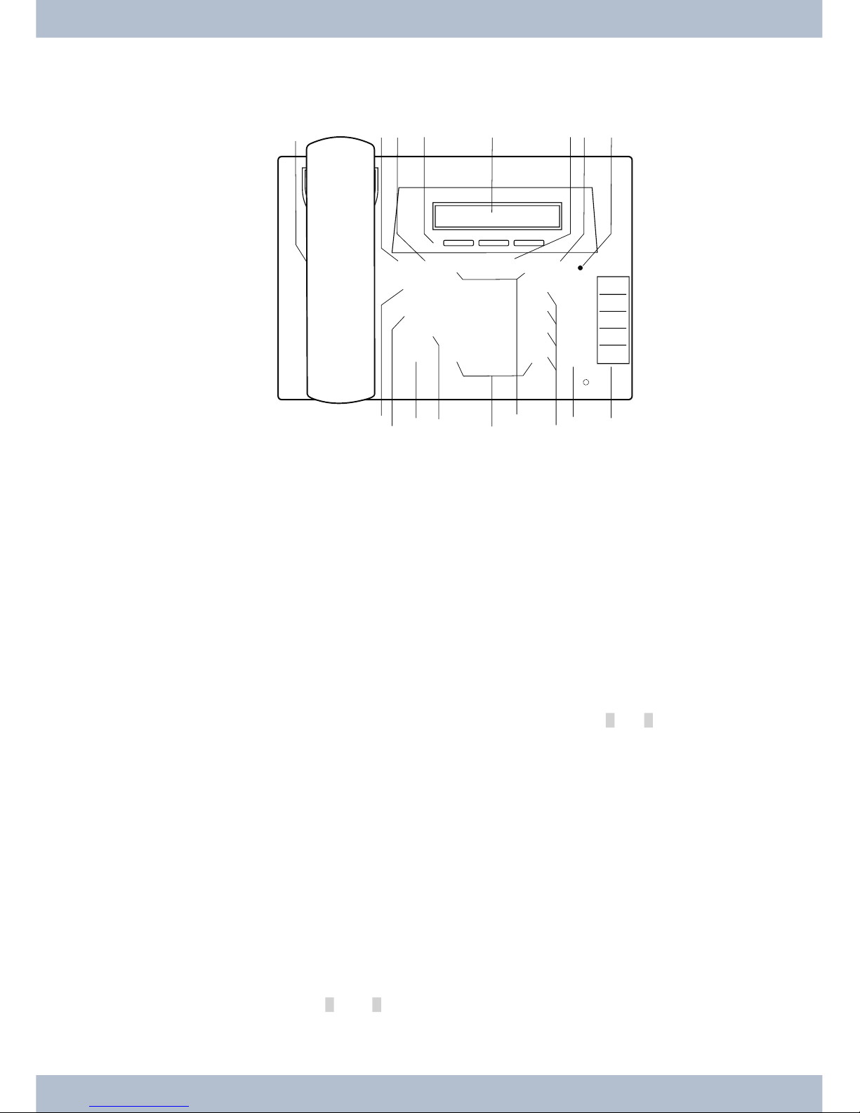
Telephone user interface
1Functionkey:Opentheprogrammingmenubypressingthiskey.Ifyouarealreadyinamenuandpressthis
key,thefunctionsavailableinthismenuwillbedisplayedoryouwillbetakenbackoneprogrammingstep.
2Escapekey:Bypressingtheescapekey,the telephoneisonceagainatrestduringprogramming.
33softkeys
In the PC configuration of the telephone you can specify whether the functions of softkeys are displayed
onlywithuppercaseorlowercase letters.
4Display: After connecting to the power supply (elmeg IP-S400) or to the internal ISDN or flush-moun-
ted(elmegCS410 ,elmeg CS410-U)connection of the elmeg PABK, the dateand time shallbe displayedto
youonthetopline.Boththedateandtimeareautomaticallycopiedfromtheelmeg PABK.Thetextdisplay-
edforafunctioninline2canalwaysbefoundabovethecorrespondingsoftkey.Ifyoupressthesoftkey,the
nextlevelis thendisplayed.
Ifnotall ofthe characterscan beshown inthe display,thisisindicatedby»»«or»»«.
5OK key: After pressing this button the setting is then stored in the telephone. You will then hear an ac-
knowledgetone.
6C-key:You can go backone menu step by pressingthiskey in any menu.If youare in input mode,you can
deleteindividualcharactersusingthiskey.
7CallreminderLED:Anincomingcallisindicatedbyrapidflashing.
8Loudspeaker
9Loudspeakerkey(handsfree keyelmegIP-S400)
0Divertkey
ßHoldkey
°Redialkey
§Arrowkey:Thearrows»{«and»}«intheright-handcornerofthetoplineofthedisplayshowyouthatyou
canaccessotherfunctions inthe secondlinebyusingthearrowkey.
Telephone user interface
1
1 2 3
4 5 6
7 8 9
0
W
T
L
R
FEO
< > C
* #
z
z
z
z
z
90ß$%& /
°§
$
21 3 6 78 54
Fig: 1

$Starkey/ hashkey
%Optionkeys/VIPkeys
&elmegCS410-U:5programmablefunctionkeyswithLEDs:Eachkeyhasatwo-colourLED(Level1 -Red/
Level2 -Yellow).TheseLEDscan beused toindicatespecificfunctions.
elmegCS410:Eachkeyhasa(red)LEDavailable.TheLEDsforbothofthelowerfunctionkeyshavetwoco-
lours(Level1-Red/Level2-Yellow).TheseLEDscanbe usedtoindicatespecificfunctions.
/Labelsforprogrammable functionkeys
Telephone user interface
2

Description and installation
Thesystemtelephonecan beoperatedby aninternalconnectorofa elmegPABXthatsupportssystemfunctions.
Together with the elmeg PABX, the system telephone provides various performance features that are typical of this
system.
The internal connector on the elmeg PABX is simultaneousand automatically the system interface for the system te-
lephone. Please consult the user’s guide for your elmeg PABX to see whether or not this offers the typical system per-
formance features combined with various system telephones.
UA complete configuration of the elmeg PABX and directly via the system telephone is possible on
all elmeg PABX (excluding elmeg hybird) using the Professional Configurator.
UA complete configuration of the telephone using the elmeg hybird is not possible. Some of the
performance features can only be set up using the telephone’s own interfaces. However, this is
only possible if the system telephone has a USB or Ethernet interface.
Functions that cannot be fully configured via the elmeg hybird are marked at appropriate points
in the text.
Differences in configuration between the elmeg PABX and the elmeg hybird
b
c
Pressasoftkeyoranarrowkey.Ontheelmeghybirdthiskeydoesnothavetobepressedagainifthedisplay
isdifferent,asthefunctionisalreadydisplayedorisnotavailable.
The following message indicates if differences exist.
Cannot be configured using the system telephone on the elmeg hybird!
A summary of these functions can be found on page 67under »Restricted system telephone configuration«.
elmeg CS410
This system telephone is designed for connection to an internal S-connector (4-wire cable) on a elmeg PABX.
elmeg CS410-U
Thissystemtelephone is designedfor connectionto an internal Up0-connector (2-wire cable) on a elmeg PABX. The
system telephone has an ISDN connection to which further ISDN terminals can be connected.
elmeg IP-S400
Thissystemtelephoneisconnected tothecorrespondingLAN connection(or network)oftheelmeg PABX byaCat.5
cable.The system telephone has an PC connection to which further IP terminals can be connected.
Setting / configuring the system telephone
On the system telephone itself, you can only perform a restricted configuration of the supported performance featu-
res. A complete configuration of the system is only possible via the corresponding connectors of theelmeg PABX.
elmeg CS410 Description and installation
3

Safety notices
·Note the ambient temperature for the storage and operation of the device in the specifications.
The device must only be connected once the permissible ambient operating temperature is
reached.
·Please note that when switching from cold to warm temperatures, condensation may form on or
in the device. Only remove the device from the packaging when the permissible ambient opera-
ting temperature has been reached.
·During a storm, you should not connect or disconnect any cables and do not make any calls.
·Only connect the cords to the connectors provided.
·Lay the cords so that they are protected in the event of an accident.
·Avoid the following influencing factors:
Direct sunlight
Source of heat (e.g. radiator)
Electronic devices (e.g. sound systems, office equipment or microwave devices)
Penetrating moisture or liquids
Aggressive liquids or vapours
High levels of dust
·Do not use the device in humid rooms or in explosive atmospheres.
·Only open the areas of the device indicated in the assembly/operating instructions.
·Do not touch the plug contactswith sharp, metal or damp objects.
·If the device is not permanently mounted, position the device or the accessory on a non-slip
surface.
·Please ensure that you only clean the system with a slightly damp cloth.
·Please ensure you only use approved accessories.
·Only terminals that offer SELV (safety extra low voltage) and/or meet ETS 300047 may be con-
nected to the device. Correct use of the permitted terminals meets these requirements.
Plug power supply unit
·Only use the plug power supply unit supplied or available as an accessory (DSA-0101F-05 UP or
L15 D52 AB DDLAWO).
·Do not use any plug power supply units that show signs of damage (breaks or cracks in the ca-
sing).
Electrostatic charges (ESD protection)
Thesystem telephone is supplied withESDprotectionabovethe permissible valuesagainsttheeffectsof electrostatic
charges. In spite of this, be sure to avoid excessive static charges. Various causes can result in the electrostatic charge
achievingvaluesthat far exceedthe permissiblevalues required and that exceed interference immunity of thesystem
telephone. The causes or circumstances such as low humidity or carpets must be eliminated. The manufacturer of
the system telephone accepts no liability for damages resulting from these causes.
Safety notices elmeg IP-S400
4

Unpacking and positioning
·System telephone.
·Receiver with cord.
·2 device feet.
·User’s guide and labels for function keys.
·( elmeg IP-S400)Adapter cable for headsets with 4-pin cord, 8-pin / 4-pin.
Setting up the system telephone
Before setting up the telephone the rear telephone device feet must be mounted 2 in the positions marked 6in the
picture.
You can adjust the display angle of the telephone to your angle of vision depending on the height of these two feet.
Make sure that both of the feet on the device are the same height.
To adjust the height, pull the device foot away from the base of the telephone. Rotate it approx. 60° along the longitu-
dinal axis and re-insert the foot into the housing. By rotating the device foot by approx. 60° along the longitudinal
axis you can adjust it to three different heights.
Please remember that the system telephone device feet may leave marks on delicate surfaces, such as on fittings for
examples. The system telephone manufacturer shall not be liable for any such damage. Please ensure therefore that
you place your system telephone on a non-slip surface.
Cleaning the system telephone
The system telephone has been designed for normal usage conditions. Only clean the device when necessary with a
slightlydamp cloth or use an anti-staticcloth.Neverusesolvents.Never use adrycloth;theelectrostatic charge could
cause electronic faults. Make sure that no moisture can enter the system telephone and cause damage.
Connecting the system telephone (connector and receiver cord)
Inordertooperateyoursystemtelephone, youmustinsertthecords forthetelephoneconnectorandthe receiver.
Connecting the receiver cord
Connectthe receiver cord 1as shownin Fig. 2. Place the receivercordinthecableguide 4and clamp it securelyun-
der the cable clips 5.
Connecting the system telephone (connector and receiver cord) Unpacking and positioning
5
23
4
56
7
4
61
Fig: 2

Connecting the cord
S-connector
Connect the S-cord 2as shown in Fig. 2(socket S0). Please note that the longer ISDN plug must be inserted in the
ISDN socket and the shorter ISDN plug must be inserted in the ISDN socket on the system telephone. Next place the
S-cord in the cable guide 4and clamp it securely under the cable clips 5.
Up0-connectorelmeg CS410-U:
Connect the S-cord 1as shown in Fig. 3(socket Up0). Please note that the longer ISDN plug must be inserted in the
ISDN socket and the shorter ISDN plug must be inserted in the ISDN socket on the system telephone. Next place the
S-cord cable in the cable guide 2and clamp it securely under the cable clips 3.
,This elmeg CS410-U may no longer be connected to an ISDN connector via an S0 socket (e.g. internal
S-connector of the elmeg PABX).
,You can connect a further ISDN terminal with S-interface (e.g. an ISDN card or another system tele-
phone) to the S0 socket on the system telephone. The power supply at this connector for another ISDN
terminal is 1 Watt.
Connecting and setting the headset (not included)
You can connect a headset to the system telephone. Please ask your dealer or consult the Internet to find out which
headsets are compatible.
elmeg CS410-U. elmeg IP-S400
Theheadset connectoron thesystemtelephone isan8-pin socket.HeadsetswithDSHGinterface(e.g.cordlessDECT
headsets) can be connected directly to the system telephone without any accessories. For standard headsets (4-pin
cord, e.g. U10PS) use the adapter cable supplied.
Unpacking and positioning Connecting the system telephone (connector and receiver cord)
6
5
4
3
2
1
Fig: 3

Connecting the headset
The headset is connected to the separate headset socket on the system telephone as shown on page 5 in Fig. 2. Next
place the headset cable 3in the cable guide 4and clamp it securely under the cable clips 5.
If the headset cord does not fit in the cable guide, stick the adhesive cable clip supplied on to the base of the system te-
lephone 7. Then lay the headset cord under this clip.
Configuring the headset
Headset connectorelmeg CS410 elmeg IP-S400
1Microphone +
2Receiver (Ground)
3Receiver
4Microphone (Ground)
Headset connector elmeg CS410-U, elmeg CS410
1DSHG receiver
2Earth (Ground)
3Microphone +
4Receiver (Ground)
5Receiver (3.3V switchable over resistance)
6Microphone (Ground)
7V+ (3.3V)
8DSHG transmitter
Other settings for the use of the headset
Youcan useeitherthereceiveror the headsettomake acall.When usingaheadset,thefollowingsettings arerequired
or available:
·In the configuration of the system telephone, set up a function key for operating the headset (he-
adset key, see page 36).
·The connected headset can be used automatically for certain operations on the system telephone
(see page ).
·If special support is saved in the system telephone for your headset, enter the corresponding type
of headset (see page 48).
e.g. the LED in the microphone of the »Firefly F142 N« from Plantronics is switched through the
system telephone.
·If you want to use the headset to automatically receive calls, set the time to automatic pickup (see
page ). In the configuration of the system telephone, set up a function key for activating or deacti-
vating automatic call pickup.
·Using the headset the answering machine can be queriedif automatic headset operation is set up.
Connecting the system telephone (connector and receiver cord) Unpacking and positioning
7
43
21
Fig: 4
87
65
43
2
1
Fig: 5

elmeg IP-S400 on the Ethernet connector
PIN configuration PoE
1Transmit Data +
2Transmit Data -
3Receive Data +
6Receive Data -
4/ 5
7/ 8
Audio in / Audio out
The telephone has an input 7and an output 8for audio signals. These connectors are intended as a headset con-
nector. The sockets are connected to the corresponding socket connectors for the headset on the base of the
telephone.
1Plug power supply unit connector
2Plug power supply unit
3Ethernet PC connector
4PC or additional IP telephone
5Ethernet / PABX connector
6elmeg PABX
7Audio-in connector (microphone)
8Audio-out connector (receiver)
9Headset with two 2.5mm stereo
jack plugs.
Changing the label field
The labels for the function keys can be found on the last page of this user guide. Remove the selected nameplate.
To change the plate, pull the flexible cover between thumb and forefinger and lift the cover upwards. The nameplate
can then be changed.
Youcanlabel thenameplateviayourPC.The elmeg PABXCD-ROMcontainsanAdobe Acrobatfilewith templates.
Pictograms
In order to be able to demonstrate some of the processes involved for setting up and operating the telephone in this
user guide, the following pictograms (symbols) listed below were used.
bLiftreceiverorstartpreparingtodial.
aReplacereceiver.
Thetelephoneisidle.
lAcallissignalled.
Thecallmelodysounds.
Unpacking and positioning Changing the label field
8
1
2
35
4
78
9
6
Fig: 7
87
65
43
2
1
Fig.: 6

gYouarein acall.
dAconferencecallisinitiated.
qYouwillhearthepositiveornegativeacknowledgementtone.
tChoosecallnumber,code,character ortext.
0...9
*,#
Pressaspecifickeyonthediallingpad.
Youcanswitch backandforthbetweenthetextdisplayedbypressingthearrowkeys
FTheconfigurationandsettingsareinitiatedbypressingthefunctionkey.
SThiskeyis asoftkey;thefunctioncorrespondstothefunctionlisted inthe display.
OYoucanconfirmanentrybypressingthe OKkey.
ZYouwillbe promptedtopressoneofthefunctionorspeeddialkeys.
zYouwillbe promptedtopressaspecificfunctionor speeddialkey.
EThe Escape key ends a current configuration without saving it. Following this the telephone is once
again in idle state. In elmeg IP-S400 entries for IP functions are completed and then transferred by
pressingEscape.
CEntries such as telephone numbers or names can be deleted by pressing the Clear key. Only one cha-
racterisdeleted eachtime thekey ispressed.
RThiskey isnecessaryformanuallyholdingan enquiry.
WTherediallingkeystarts theredialling;pressing ita numberof times startsthe advancedredialling or
theautomaticredialling.
TAnycurrentconnectionscanbeterminatedby pressingthe disconnectkey.
LThesystemtelephone loudspeakerisswitchedonoroffbypressingtheloudspeakerkey.
#IfyouenteracallnumbertodialviaaSIPprovider,thenumberdialledisoutputapprox.5secondsaf-
terenteringthelastdigit.Ifyouendthecallnumberwiththehashkey,thesystemdialsautomatically.
Theterminalmust beable todial thehash keyin tothePABX.
Pictograms Unpacking and positioning
9

System telephone settings
Connection and operation of the elmeg IP-S400 to the elmeg PABX /elmeg hybird (Basic operation with
DHCP)
Please ensure your read the elmeg PABX assembly instructions in order to see which connectors are intended for the
connectortotheelmeg IP-S400.Connectthe connectorto theEthernetPABX connectoron thesystemtelephone.
·Configure the elmeg PABX for use with IPS system telephones.
·Set the MSN of the IPS system telephones in the elmeg PABX.
·Connect the power supply (plug power supply unit) to the IP system telephone and wait until the
system telephone has initialised.
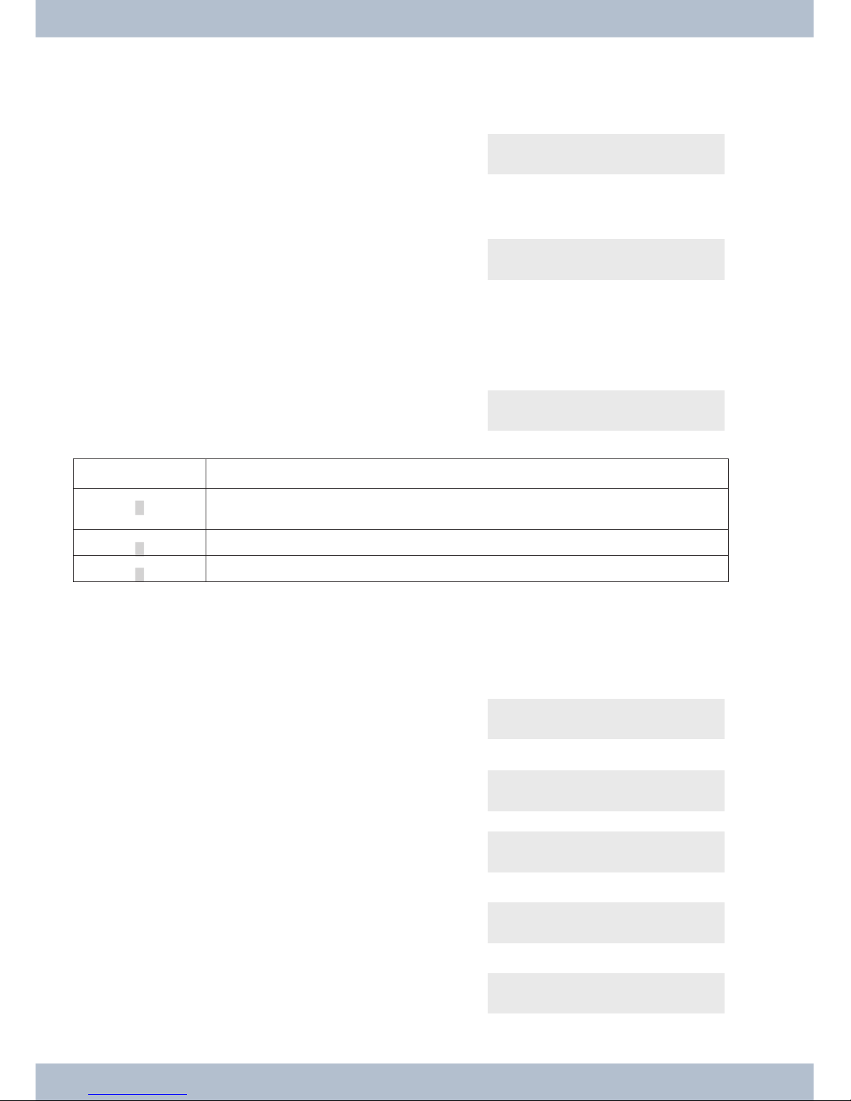
If the IP system telephone is initialised, you will be prompted to choose a language in the display.
Select the language for the display.Press the ar-
row keys to select the languages that are available
and confirm with O.
Welche Sprache? }
deutsch english polski
Enter one of the elmeg MSN entered in the PABX
(example 12) .Confirm the entry with O.
Program dial number
MSN-1>12
If no PIN is entered in the system configuration,
press Oand Oagain when prompted.
Please enter login PIN
TNM-1->
SSwitch on »Use DHCP?«.Select »on«. Use DHCP?
off on
System telephone and elmeg PABX are synchronised.
,If there is no connection to the elmeg PABX (no LAN connection or the system telephone is not regis-
tered), the time in the display is replaced by »©---/ /--‰«.
You can now use the IP system telephone like a system telephone on ISDN or UP0.
A complete description of the configuration can be found on page .
Possible error:
IP address, IP gateway, IP subnet mask, IP SYS server.
MSN is not entered in the elmeg PABX or is used multiple times.
A PIN / login name is entered in the elmeg PABX but not in the telephone.
No extension is set up in the elmeg PABX.
You can now use the IP system telephone like a system telephone on S or UP0 connectors.
Setting the display language
You can choose in which language the display is to appear.
System telephone settings Setting the display language
10

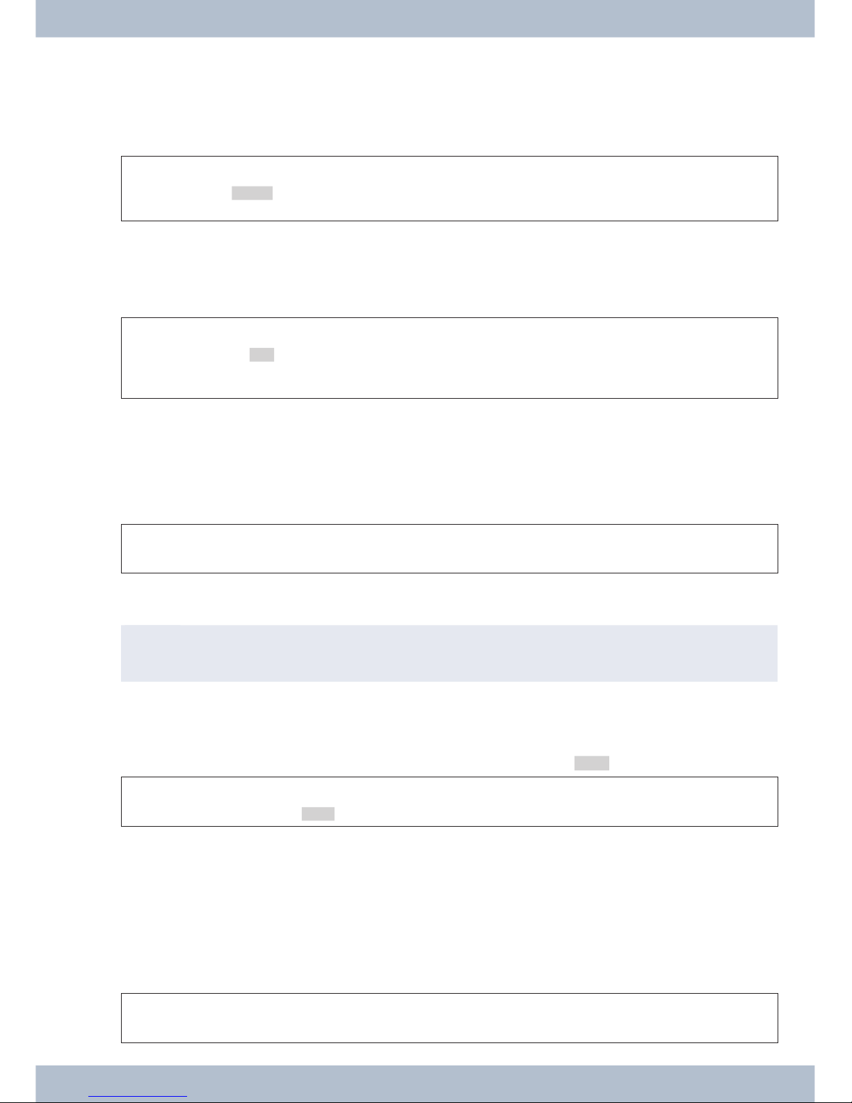
Start as follows:
aFSSS
Replace receiver config. display language
Pressthe arrowkeys toseethe languagesthat areavailable. Which language? }
deutsch english polski
F-3-1-2-Example:
Pressthe arrowkeys toseethe languagesthat areavailable. Which language? }
deutsch english polski
SPress the softkey under the chosen language. The display is
immediately switched to the chosen language.
Entering letters and numbers
If you press a key several times, you will see characters (letters or numbers) displayed in sequence.
For the entry of letters and digits, the keys are assigned as follows:
Key First press Second
press
Third press Fourthpress Fifth press Sixth press Seventh
press
11
2ABC2ÄÅÆ
3DEF3€
4GHI4
5JKL5
6MNO6ÖØ
7PQRS7ß$
8TUV8Ü
9WXYZ9¥
**
##
All of the letters entered are displayed in uppercase.
Example: »bintec elmeg«.
The »0« key has a number of special characters on it.
E.g.: »!«, »&«, »?«, »+«, »-«, »=«, »(«, »)«, »@«, »$«, …
When the 0is first pressed it inserts a space. If the key is pressed a second time, several special characters are
shown in the display. To select a special character, press the allocated keys 1... . If you want to view other special
characters, press the 0key.
Setting the display language System telephone settings
11
Display of the performance features set up
When the telephone is at rest, the date and time are dis-
playedinthe top line of the display; the phonebook (tbuch)
andVIP informationaredisplayedin the bottomlineofthe
display.
22.11.09 08:30 }
tbook vip
>
S
In order to view further information about the various
functionsthat are set up,pressthe right arrow key and then
the softkey under the desired function.
22.11.05 08:30 i S U {
mail charge info
>
Additional display information
Whenthetelephoneisatrest,additionalinformationon the functions that are setup is displayedin the top lineofthe
display. 22.11.09 08:30 S U }
tbook vip
Display Function set up
»S«Dial control or call filter activated,
Access to system telephone menus protected
»U«Call diversion (call forwarding) set up.
»i«Status info text is available (e.g. router key).
Displays
Softkey »mail«
Select between »uus« und »sms«. Messages
uus sms
UUS
Select between »list« und »sms«. Messages / UUS }
list new
<You can choose between 5 messages by using the arrow
keys.Select thedesiredentry toeditby pressingtheO key.
Select text {}
1: HELLO
SIf you wish to send or delete the message, press the corre-
sponding»send«or»delete?« softkey(example:»send«).
1/HELLO
send delete?
SPress the »UUSHello« softkey. Send mail (Abc)
UUS> HELLO
System telephone settings Setting the display language
12

SYou can select the desired call number to which the UUS is
due to be sent between »speed dialling«, »vip«, »repeat«
and »new«. Press the corresponding softkey.
Send mail / UUS }
direct vip new
Setting the display language System telephone settings
13

Telephoning
Initiate a call
Dial call number - without option to make a correction
btg
Lift the receiver Dial call number Call
Dial call number - with option to make a correction
atbg
Replace receiver Dial call number Lift the receiver Call
To amend the call number or to correct an incorrect entry, select the incorrect digit with the arrow keys and press the
C key to delete it. Then enter the correct digit.
Ifyou want to carryoutthe call using thereceiver,lifethereceiverafter entering thecallnumber.At any timeduringa
call, you can switch back and forth between hands free (only elmeg IP-S400), receiver and loudspeaker.
Afteryouhaveenteredacall number,you can also press the loudspeaker key in order to be able to selectthe callnum-
ber and use the hands free system (only elmeg IP-S400).
After you have entered a call number, you can also press the loudspeaker key in order to be able to select the call
number.
Ifit isnotpossible to connectacall (e.g.callnumberblockedbydialcontrol),amessage tothiseffectwill appear inthe
telephone display; e.g.: »Blocked: Call no.«, if the dial control is activated.
If you have lifted the receiver and you are not connected, you can accept a call waiting via the »accept« softkey wit-
hout having to replace the receiver. You will be notified of the call by a brief message. If you set up a connection key,
you can accept the call straight away by pressing the key.
Other options for dialling when the receiver is replaced
Itis also possible to dial anumberwhen thereceiver is replaced and to corrector supplementacall numberbefore di-
alling when calling:
•from the redial memory (see page 16).
•from the caller history(see page 24).
•from the phone book on the PABX (see page ).
•from the VIP memory (see page 24).
•using the function keys (see page 15).
•via the PABX CTI (TAPI) function (elmeg CS410 / elmeg CS410-U).
If you want to use one of these options, you can make further entries before initiating the call. You can determine, for
example, whether or not a call number (MSN) is to be transmitted to the called party.
Telephoning Initiate a call
14
Select from the phone book on the PABX
If you are using the system telephone on a PABX with system telephony, you can dial from the phone book on the
PABX.
aStO<> Obg
Replace recei-
ver
tbuch Enter the initial
letters Entry
select Lift the recei-
ver Call
Dialling from the VIP memory
You can programme a VIP entry for each of the 10 dialling keys consisting of a name (max. 20 characters) and a call
number (max. 26 digits).
aS<> or tbg
Replace recei-
ver
VIP VIP destination
select
VIP destination
select
Lift the receiver Call
The procedure for programming VIP entries is described on page 24of this user guide.
Speed dial with function keys
Speeddialling is initiated using the function keys. You can programme two functions or speed dials undereach of the
five keys.
aZb g
Replace receiver Pressing the function keys Lift the receiver Call
Dial the required call number using the function keys.
If you want to dial a number in the second layer, press the desired key twice. This must be done quickly.
,Programming of the speed dial/function keys is done via the PC configuration or the advanced confi-
guration page 47.
Select from the caller history
The telephone has a caller history. A maximum of 10 entries (calls, SMS or UUS1 text messages) shall be possible in
this list. Entries in the caller history are shown on the display by pressing the »list« softkey.
aS<> bg
Replace receiver list Select entry Lift the receiver Call
You will find further information on the caller history on page 24of this user guide.
Accepting/rejecting a call
With respect to the telephone’s basic settings, each call shall be signalled irrespective of the dialled call number
(MSN). If two calls are signalled simultaneously, the first call is accepted when the receiver is lifted. The second call
may continue to be signalled by means of the call waiting signal.
Thenumber of thecallerandthenumber dialled by the caller (MSN-1…MSN-3,or assignedname) are shownonthe
telephone display. If only MSN-1 is entered, only the entered name is displayed and not the number.
a l b g
Replace receiver Lift the receiver Call
Accepting/rejecting a call Telephoning
15

Ifyou are unable to or do notwish to accept acall,you can reject the call. Pressthe »reject« softkey andthe call will
no longer be signalled to your telephone. If you are a member of a team, the call is signalled to other telephones in the
team. If the call was only signalled to your telephone, Busy is signalled to the caller after it has been rejected.
a l S
Replace receiver reject
Forwarding a call (Call Deflection)
Ifyou areunabletoordo not wishto acceptacall,youcanforwardthecall.Pressthe»transfer«softkeyin order to
forward the call directly to another extension. The call number to which the call is due to be forwarded can be preset
in the telephone configuration for each call number (MSN).
After pressing the »transfer« softkey you can either forward the call to the preset call number by pressing the OK
key or enter a new call number.
a l StO
Replace receiver transfer Dial call number (if no call num-
ber has been preset)
Suppressing the call number (anonymous call)
Ifyou do not want yourcallnumberto be sent tothecalledparty, you can suppressthetransmissionof your callnum-
ber. You can set this function specifically for the next call or permanently (see page 32). The performance feature »ad
hoc suppression of call number« must be requested from the network provider.
Suppressing transmission of the call number for the next call
Youcan performinternalor externaldiallingsothatthecall number(MSN) isnottransmittedfromyoursystemtele-
phone to the called party.
atOFSbg
Replace recei-
ver Dial call number secret Lift the recei-
ver Call
Ifa call issignalled,you can decide before acceptingthecall whether or notyourcallnumber shouldbetransmittedto
thecaller. If your systemtelephone is thedestination of a calldiversion, you can usethis procedure to prevent thecall
seeing the call number of the diversion destination (your number).
a l > S b g
Replace receiver secret Lift the receiver Call
Initiating a call with a fixed call number (MSN)
You can perform internal or external dialling so that a specific number (MSN) is transmitted from your system tele-
phone to the called party. This call number must first be entered in your system telephone. During selection you will
seethe callnumbertransmitted(»MSN-1«...»MSN-3«)orthe nameyouhaveassignedto thiscallnumber(MSN).
You can initiate dialling with a fixed number as described below or use a programmed function key (MSN
assignment or user key).
a t OFSS b g
Replace receiver Dial call num-
ber
msn msn-
...
1 msn-3
Lift the receiver Call
Redialling
The last number dialled is stored in the redial memory.
Telephoning Forwarding a call (Call Deflection)
16
This manual suits for next models
2
Table of contents
Other BinTec Telephone manuals


