BinTec elmeg CS410 User manual

Operating instructions
English
elmeg CS410
elmeg CS410-U
elmeg CS400xt
elmeg IP-S400
Answering machine
T400, T400/2
Please note!
The system telephones and corresponding systems in this user guide use the following abbreviations:
System/PABX: Abbreviation:
elmegPABX elmeg PABX
elmegHybird300
elmegHybird600
elmeg hybird. Alternative configuration of the system telephones (see also page )
BintecTR200aw as PABX
BintecTR200bw as PABX
Declaration of Conformity and CE Mark
This device meets the requirements of R&TTE Directive 1999/5/EC:
Directive 1999/5/EC of the European Parliament and of the Council of 9 March 1999 on radio equip-
mentandtelecommunicationsterminalequipmentandthemutual recognitionoftheir conformity.
The Declaration of Conformity can be viewed at the following web address: http://www.bintec-elmeg.com.
The crossed-out waste bin icon on the device indicates that the device must be disposed of separately
from normal household waste at the disposal sites provided at the end of its service life. You can find
additional information on the individual return of used devices at www.bintec-elmeg.com.
© bintec elmeg GmbH - All rights reserved.
Thisdocumentmaynotbereproduced, in full or inpart,exceptwiththeapprovalof the publisher and with adetailed
reference to the source publication, irrespective of the nature and method or media (mechanical or electronic) by
which this is produced.
Functional descriptions of this documentation that relate to software products of other manufacturers are based on
thesoftware usedatthe time ofcreationor printing.Theproductorcompanynames usedinthis documentationmay
in some cases be registered trademarks.
B

Table of contents
Telephone user interface .......................................1
Description and installation.....................................3
Extensions for the system telephone...........................................5
Safety notices .............................................6
Unpacking and positioning the system telephone ........................7
Connecting the system telephone to a PC .......................................10
Changing the label field .................................................12
Pictograms ........................................................12
System telephone settings .....................................14
Setting the display language...............................................15
Additional keyboard ........................................19
Telephoning .............................................21
Initiate a call .......................................................21
Accepting/rejecting a call ................................................22
Forwarding a call (Call Deflection)...........................................23
<$I[English]Initiate call;Without call number (CLIR)>Suppressing the call number (anonymous call) ....23
Initiating a call with a fixed call number (MSN) ...................................23
Redialling .........................................................24
Switching the microphone on/off, loudspeaker and hands free ...........................25
Using the headset.....................................................26
Announcement ......................................................26
Simplex operation ....................................................27
Automatic callback....................................................28
Park (only elmeg CS410and CS410-U).........................................29
Intercept (MCID) (only via the S/U connector) ....................................29
Keypad and tone dialling (MFC dialling) .......................................30
Telephoning with several people .................................31
Call Waiting........................................................31
Hold for enquiry .....................................................31
Call forwarding (call transfer) .............................................31
Brokering .........................................................31
Conference ........................................................32
Operate system telephone .....................................33
Phone book ........................................................33
VIP memory .......................................................35
Caller and message list..................................................36
SMS and UUS1 text messages..............................................40
Table of contents
I

Do not disturb ......................................................45
Checking costs ............................................46
Viewing and deleting costs ...............................................46
Set up tariff factor and denomination .........................................47
<$ I[English]Credits Based Accounting System><Setting the call costs account for a number .........47
Release or block call number (MSN) for dialling ...................................48
Call and cost display ...................................................48
System telephony ..........................................51
Function keys .......................................................51
Function keys when connecting to a elmeg hybird or PABX ............................52
System menu on elmegPABX with system telephony .....................61
Advanced configuration ......................................63
Settings ..........................................................63
Operation .........................................................64
Block............................................................64
Configuring and setting the system telephone .........................66
Acoustic ..........................................................66
settings ..........................................................70
Configuration ............................................77
elmeg IP-S400 configuration ..............................................83
Number programming .......................................86
Macro .................................................88
Macro programming...................................................88
System telephone and PC......................................91
CTI / TAPI via the USB connector on the system telephone.............................91
CTI via the USB connector on the system telephone .................................91
Audio applications via the audio connectors on the system telephone.......................91
Content of WIN-Tools CD-ROM ............................................92
Installing the program from the CD-ROM ......................................93
Basic system telephone settings ..................................95
Technical Data ......................................................96
Answering machine .........................................97
General configuration .................................................101
Announcements, information messages and dictations ..............................104
Activating message recording for each number (MSN)...............................106
Operation ........................................................112
Remote operation....................................................115
Remote operation access numbers ..........................................117
Use answering machine through another telephone ................................118
Table of contents
II

Software ...............................................121
System telephone menu ................................................125
Options................................................129
Index .................................................131
Quick Install Guide.........................................141
Table of contents
III

Table of contents
IV
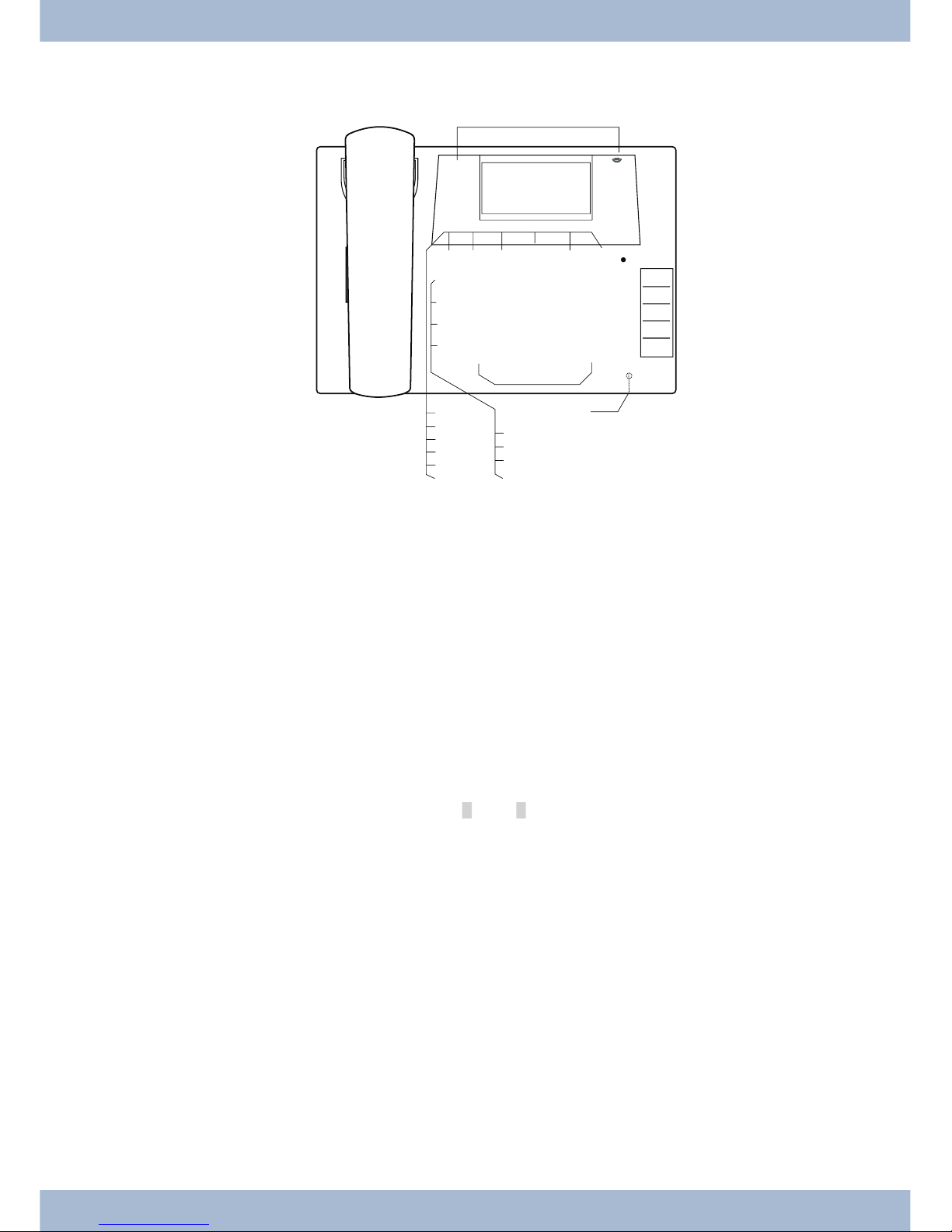
Telephone user interface
1Loudspeaker
2Receiverwithconnectorcord
3ThePABX menuis called for CS400xt.
46softkeys
57-linedisplaywithbackgroundlighting
6Menu key: Open the programming menu by pressing this key. If you are already in a menu and press
thiskey,thefunctionsavailableinthismenuwillbedisplayedoryouwillbetakenbackoneprogram-
mingstep.
7ESCkey:Bypressing the ESC key (Escapekey), the system telephone is once again at rest during pro-
gramming.
80 Right/left arrow keys: The arrows »{« and »}« in the right-hand corner of the top line of the display
showyouthat youcan accessotherfunctions inthebottomlinebyusingthearrowkeys.
9OKkey:Pressingthisbuttonconfirmsanentryandstoresasettinginthesystemtelephone.
ßC-key:Youcangobackone menustepbypressingthiskeyinanymenu.Ifyou areininputmode,you
candeleteindividual charactersusingthiskey.
°Starkey/ hashkey.
§Diallingkeys.
$Loudspeaker/handsfreekey.
%Disconnectkey.
&Redialkey.
/Holdforenquirykey.
(Microphone.
Telephone user interface
1
1 2 3
4 5 6
7 8 9
0
W
T
L
R
MEO< > C
* #
K
K
K
K
K
K
K
z
z
z
z
z
01.01.10 10:10
Info -r-i-
Telefonbuch Ruhe
VIP Anruferliste
2
1
3
6
7
8
9
0
ß
°§
$
%
&
/
(
)
=
Q
5
4
°
Bild:

)elmeg CS410 / CS410-U, IP-S400: 5 programmable function keyswith LEDs: Each key has a two-co-
lourLED(Level1-Red/Level2-Yellow).TheseLEDscanbeusedto indicatespecificfunctions.
CS400xt:5programmablefunctionkeyswithLEDs:
Eachkeyhas a(red) LEDavailable.TheseLEDscan beused toindicatespecific functions.
TheLEDsforbothofthelowerfunctionkeyshavetwocolours(Level1-Red/Level2-Yellow).
=Labelfieldforfunctionkeys.
QStatus LED, LED for call signalling, signalling received messages UUS, SMS and MWI (red) and ans-
weringmachine(yellow).Thedesired functiondisplay formessagesandcallscanbeconfigured.
Telephone user interface
2

Description and installation
The system telephone can be operated by an internal connector of a elmegPABX that supports system functions.
Together with the elmegPABX, the system telephone provides various performance features that are typical of this
system.
The internal connector on the elmegPABX is simultaneous and automatically the system interface for the system te-
lephone. Please consult the user’s guide for your elmegPABX to see whether or not this offers the typical system per-
formance features combined with various system telephones.
UA complete configuration of the CS400xtPABX and directly via the system telephone is possible
on all elmegPABX (excluding elmeg hybird) using the Professional Configurator.
UA complete configuration of the telephone using the elmeg hybird is not possible. Some of the
performance features can only be set up using the telephone’s own interfaces. However, this is
only possible if the system telephone has a USB or Ethernet interface.
Functions that cannot be fully configured via the elmeg hybird are marked at appropriate points
in the text.
Differences in configuration between the elmegPABX and the elmeg hybird
bb
cc
Pressasoftkeyoranarrowkey.Ontheelmeghybirdthiskeydoesnothavetobepressedagainifthedisplay
isdifferent,asthefunctionisalreadydisplayedorisnotavailable.
The following message indicates if differences exist.
Cannot be configured using the system telephone on the elmeg hybird!
A summary of these functions can be found on page under »Restricted system telephone configuration«.
CS400xt
This system telephone is delivered with a key extension module (T400/2), providing you with 10 additional, freely
configurable keys.
It is designed for connection to an internal S0 port (4-wire cable) of a PABX system. The system telephone is not
equipped with a USB or serial port for configuration or other uses. This phone must be configured via the internal
ISDN port using the WinTools Professional Configurator. There are also no »Audio functions« implemented and
you can not use the Answering machine or Up0 modules or functions. None of the functions for this module are
shown in the display, nor can they be used.
This telephone is equipped with the function »Emergency operation«. »Off« = Emergency
operation off, »On« = Emergency operation On. meaning it can be operated at NT via the
PABX system on a loss of 230 V~ power. If more than one telephone is connected to the
ISDN system, the emergency operation function may only be configured on one of the
ISDNsystemtelephones. Allcallsare signaledat thisphone.Thevolume oftheringing tone
isset tolow.Inaddition tomakingnormalcalls,the followingfunctionsarealso available:
Description and installation
3
OFF
ON

·Selection of a call number from the telephone directory or the speed dial memory after lifting the
handset.
·Display of call duration and costs.
·Mute.
·Terminate call.
The phone number (MSN) that the network service provider assigned to you as the first (master) number will be
transmitted to external subscribers. Charge billing is effected for this. Observe the information concerning emer-
gency operation in the PABX system. Ongoing connections are interrupted in the event of a power failure.
,
Refer to the operating manual of your PABX system to see if your system supports emergency operation.
Configuring emergency operation (PtMP and PtP connections)
Emergency operation is not configured as a factory default feature. A slide switch is located on the bottom of the sys-
tem telephone that can be used for configuring emergency operation.
To configure the emergency operation feature, slide the switch on the left side on the bottom of the phone down. To
de-activate emergency operation, slide the switch back to the top position.
,
Attention: Before you move the emergency operation switch unplug the ISDN connector for the system te-
lephone. Use a non-metallic tool to move the switch.
Configuring emergency operation at a point-to-point (PtP) connection
Ifyou wish to also use yoursystemtelephone foremergencyoperation at a PtP connection you mustalso activate this
feature using the PC configuration for your system telephone. You can use the configuration program to set emer-
gency operation at a PtP connection.
Making calls during emergency operation at a point-to-multipoint connection
The system telephone begins emergency operation when power supply for the PABX system and the NT is lost.
Emergency operation, followed by a telephone symbol is then shown in the system telephone display.
If the 230 V AC power supply is restored during an ongoing call, all normal, configured functions are available again
onlyafter youhangup the handset. Ifthe 230V~ power supplyisrestored when thehandsetis in thecradle,the emer-
gency operation display is replaced by the normal display when the handset is lifted, or on the next call.
Making calls at emergency power supply mode on a point-to-point connection
Duringemergencypowersupplymodeatapoint-to-pointconnection,youwillseethenormaloperationdisplays.
elmeg CS410
This system telephone is designed for connection to an internal S-connector (4-wire cable) on a elmeg PABX. If you
want to use the telephone on an internal Up0 connection, you must install the internal module »Up0/S0« on the tele-
phone or use the external »Up0/S0« converter.
Description and installation
4

CS410-U
This system telephone is designed for connection to an internal U-connector (2-wire cable) on a elmeg PABX. You
then no longer require the internal module »Up0/S0« or the external »Up0/S0converter«.
Settings / Configuration elmeg CS410, CS410-U. CS400xt
On the system telephone itself, you can only perform a restricted configuration of the supported performance featu-
res. A full configuration is only possible with the Professional Configurator from the WIN-Tools CD-ROM via the
USBinterface on the system telephone or theinternal S/U-connector(please refer to pageB to seewhetherornot this
function is supported) on a PABX.
elmeg IP-S400
This system telephone is connected to the corresponding LAN connector (or network) of the PABX via a Cat. 5 cable.
The system telephone has a PC output to which further IP terminals can be connected. The system telephone has a
hands free function.
Power supplied via plug-in power supply unit, or via Ethernet PoE (Power over Ethernet).
,
A further description on configuring the system telephone can be found in the detailed user guide on the
CD-ROM.
Extensions for the system telephone
Module Up0/S0 (elmeg CS410, CS410-U, CS400xt)
·To connect the system telephone to a U-connector on a PABX, you can install the »Up0/S0« mo-
dule on your system telephone. You then no longer need the external »Up0/S0-Converter«.
Answering machine module (only elmeg CS410, CS410-U)
·This module expands your system telephone with a digital answering machine offering nume-
rous functions.
E.g.: Individual configuration for each number of the system telephone, time control of the an-
nouncement for each number, automatic notice for recorded calls, recording of dictations, liste-
ning in on calls, PIN-protected remote operation.
A special key and an LED are provided for the operation of the answering machine.
Key extension T400
·The key extension has 20 keys with LEDs that can be used in two layers as function keys. The LED
is assigned to the first key layer. Two other LEDs are used to display additional information.
You can connect up to three key extensions in sequence (cascading) to your system telephone. A
plug power supply unit must be used if using more than two key extensions. Only use the plug po-
wer supply unit (220872.5) or T1-UK (220873.3) available as an accessory.
Key extension T400/2
·The key extension has 10 keys with LEDs that can be used in two layers as function keys. The LED
is assigned to the first key layer. Two other LEDs are used to display additional information.
Extensions for the system telephone Description and installation
5

Description and installation Extensions for the system telephone
6

Safety notices
·Note the ambient temperature for the storage and operation of the device in the specifications.
The device must only be connected once the permissible ambient operating temperature is
reached.
·Please note that when switching from cold to warm temperatures, condensation may form on or
in the device. Only remove the device from the packaging when the permissible ambient opera-
ting temperature has been reached.
·During a storm, you should not connect or disconnect any cables and do not make any calls.
·Only connect the cords to the connectors provided.
·Lay the cords so that they are protected in the event of an accident.
·Avoid the following influencing factors:
Direct sunlight
Source of heat (e.g. radiator)
Electronic devices (e.g. sound systems, office equipment or microwave devices)
Penetrating moisture or liquids
Aggressive liquids or vapours
High levels of dust
·Do not use the device in humid rooms or in explosive atmospheres.
·Only open the areas of the device indicated in the assembly/operating instructions.
·Do not touch the plug contactswith sharp, metal or damp objects.
·If the device is not permanently mounted, position the device or the accessory on a non-slip
surface.
·Please ensure that you only clean the system with a slightly damp cloth.
·Please ensure you only use approved accessories.
·Only terminals that offer SELV (safety extra low voltage) and/or meet ETS 300047 may be con-
nected to the device. Correct use of the permitted terminals meets these requirements.
Plug power supply unit
·Only use the plug power supply unit supplied or available as an accessory (DSA-0101F-05 UP or
L15 D52 AB DDLAWO).
·Do not use any plug power supply units that show signs of damage (breaks or cracks in the ca-
sing).
Electrostatic charges (ESD protection)
Thesystem telephone is supplied withESD protectionabove the permissible values against the effects of electrostatic
charges. In spite of this, be sure to avoid excessive static charges. Various causes can result in the electrostatic charge
achievingvaluesthat far exceedthe permissible valuesrequired and that exceed interference immunity of the system
telephone. The causes or circumstances such as low humidity or carpets must be eliminated. The manufacturer of
the system telephone accepts no liability for damages resulting from these causes.
Extensions for the system telephone Safety notices
7

Unpacking and positioning the system telephone
Unpacking
·System telephone.
·Receiver with cord.
·2 device feet.
·S-connector cord, approx. 6 m (only elmeg CS410 and CS410-U).
·Cat.5 connector cord, approx. 2 m (only elmeg CS410 and CS410-U).
·PC connector cord, USB cable, approx. 3m (only elmeg CS410 and CS410-U).
·PC audio cord, 3.5mm stereo jack plug, approx. 2.5m (only elmeg CS410 and CS410-U).
·Adapter cable for headsets with 4-pincord, 8-pin / 4-pin.
·Cable clip, after removing the adhesive protective film (only elmeg CS410 and CS410-U).
·User’s guide and labels for function keys.
·WIN-Tools CD-ROM, including:
Professional Configurator, phone book, download and sound managers,
TAPI, USB, CAPI and NDISWAN drivers, Adobe Acrobat Reader,
Operator’s manual and Adobe Acrobat file for printing your own labels.
Setting up the system telephone
Beforesetting uptherear device feetmustbe mountedon thesystemtelephone in thepositionsmarked6in thepic-
ture.
Please remember that the system telephone device feet may leave marks on delicate surfaces, such as on fittings for
examples. The system telephone manufacturer shall not be liable for any such damage. Please ensure therefore that
you place your system telephone on a non-slip surface.
Cleaning the system telephone
The system telephone has been designed for normal usage conditions. Only clean the device when necessary with a
slightlydamp cloth or use an anti-staticcloth.Neverusesolvents.Never use adrycloth;theelectrostatic charge could
cause electronic faults. Make sure that no moisture can enter the system telephone and cause damage.
Connecting the system telephone (connector and receiver cord)
Inordertooperateyoursystemtelephone, youmustinsertthecords forthetelephoneconnectorand thereceiver.
Connecting the receiver cord
Connect the receiver cord 1as shown in Fig. . Place the receiver cord in the cable guide 4and clamp it securely un-
der the cable clips 5
Unpacking and positioning the system telephone Extensions for the system telephone
8
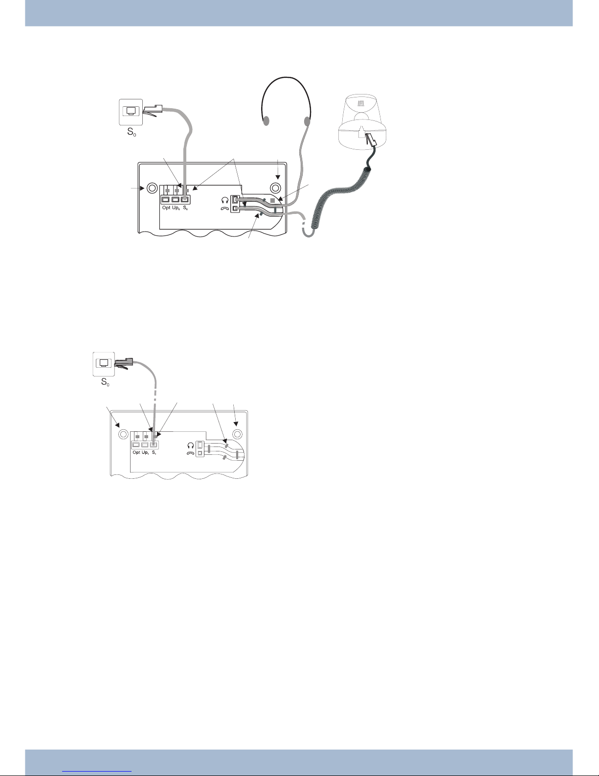
Connecting the cord
S-connector
Connect the S-cord 2as shown in Fig. (socket S0). Please note that the longer ISDN plug must be inserted in the
ISDN socket and the shorter ISDN plug must be inserted in the ISDN socket on the system telephone. Next place the
S-cord cable in the cable guide 4and clamp it securely under the cable clips 5.
Extensions for the system telephone Unpacking and positioning the system telephone
9
1
256
63
Figure: 3
23
4
56
7
4
61
Figure:

Up0-connectorCS410-U, telephone with »Up0/S0« module)
Connect the S-cord 1as shown in Fig. (socket Up0). Please note that the longer ISDN plug must be inserted in the
ISDN socket and the shorter ISDN plug must be inserted in the ISDN socket on the system telephone. Next place the
S-cord cable in the cable guide 2and clamp it securely under the cable clips 3.
,
The elmeg CS410 with »Up0/S0« module and the CS410-U may no longer be connected to an ISDN connec-
tor via an S0 socket (e.g. internal S-connector of the PABX).
,
You can connect a further ISDN terminal with S-interface (e.g. an ISDN card or another system telephone)
to the S0 socket on the system telephone. The power supply at this connector for another ISDN terminal is 1
Watt.
Connecting and setting the headset (not included)
You can connect a headset to the system telephone. Please ask your dealer or consult the Internet to find out which
headsets are compatible.
Theheadset connectoron thesystemtelephone isan8-pin socket.HeadsetswithDSHGinterface(e.g.cordlessDECT
headsets) can be connected directly to the system telephone without any accessories. For standard headsets (4-pin
cord, e.g. U10PS) use the adapter cable supplied.
,
The optional answering machine moduleand a headset with DSHG interface canbe connection to/installed
on the CS410-U simultaneously.
Connecting the headset
Theheadsetisconnectedto the separate headset socket on the system telephone as shown on page in Fig.. Next place
the headset cable 3in the cable guide 4and clamp it securely under the cable clips 5.
If the headset cord does not fit in the cable guide, stick the adhesive cable clip supplied on to the base of the system te-
lephone 7. Then lay the headset cord under this clip.
Unpacking and positioning the system telephone Extensions for the system telephone
10
5
4
3
2
1
Figure:
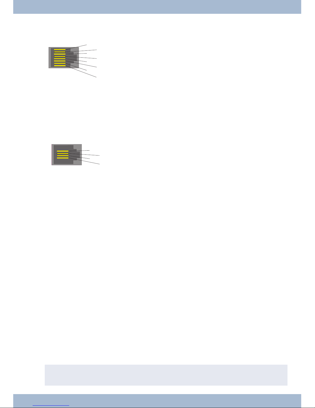
Configuring the headset connector elmeg CS410/CS410-U
8DSHG transmitter
7V+ (3.3V)
6Microphone - (Ground)
5Receiver (3,3V switchable over resistance)
4Receiver (Ground)
3Microphone +
2Earth (Ground)
1DSHG receiver
Configuring the headset connector CS400xt
4Microphone - (Ground)
3Receiver (3,3V switchable over resistance)
2Receiver (Ground)
1Microphone +
Other settings for the use of the headset
Youcan useeitherthereceiveror the headsettomake acall.Whenusinga headset,thefollowingsettingsarerequired
or available:
·In the configuration of the system telephone, set up a function key for operating the headset (he-
adset key, see page 53).
·The connected headset can be used automatically for certain operations on the system telephone
(see page 60).
·If special support is saved in the system telephone for your headset, enter the corresponding type
of headset (see page 63).
e.g. the LED in the microphone of the »Firefly F142 N« from Plantronics is switched through the
system telephone.
·If you want to use the headset to automatically receive calls, set the time to automatic pickup (see
page 71). In the configuration of the system telephone, set up a function key for activating or de-
activating automatic call pickup.
·Using the headset the answering machine can be queriedif automatic headset operation is set up.
Connecting the system telephone to a PC
Connecting the PC connecting cord (USB)
,
Usethe USB cablesupplied to connectthesystemtelephone tothePCor a hub.Ifyou use anotherUSBcable,
note that the distance between the system telephone and PC or telephone and hub must not exceed five me-
Connecting the system telephone to a PC Unpacking and positioning the system telephone
11
43
21
Figure: 6
87
65
43
2
1
Figure:
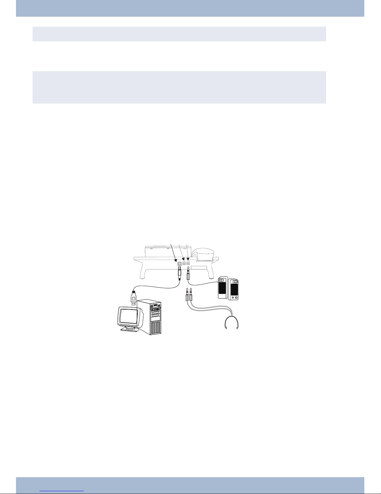
tres depending on the type of USB cable used.
Connect the USB cable (4) as shown in Fig. (socket PC). Insert the USB plug (type A) into the corresponding connec-
toron your PCandtheUSBplug (type B) intotheUSBconnector onthebackof the systemtelephone(1).Ifboth devi-
ces (system telephone and PC) are switched on, the PC recognises the connected system telephone automatically.
,
When connecting the system telephone to a PC for the first time, the device driver installation starts auto-
matically.InserttheWIN-Tools CD-ROMforthe systemtelephoneandfollow theinstructionson screen.
If you want to use several USB terminals on your PC, you will require a hub (USB distributor). The hub is connected
to the USB port on the PC. You can connect other USB terminals to the hub, including the system telephone.
elmeg CS410, CS410-UConnecting the audio cable (Audio in / Audio out)
The system telephone has an input 2and an output 3for audio signals. These connectors are designed for 3.5 mm
stereo jack plugs. When using the optional answering machine module, you can connect the system telephone over
this connection to the sound card on your PC in order to transfer announcements to the system telephone or to save
recorded messages to the PC.
You can also use specific functions on the system telephone from the audio-out output (see page 66). Connect the
loudspeaker(5)usinga 3.5mmjackplugtotheaudio-outconnectoronthe systemtelephone(3)asshowninFig. .
elmeg IP-S400 on the Ethernet connector
The elmeg IP-S400 can be powered via the Ethernet connector in accordance with IEEE Std 802.3af-2003 (PoE). The
powersupply isthenprovidedoverEthernet from thehubor switch. »AlternativeA«and»AlternativeB«are suppor-
ted on the connector in accordance with IEEE Std 802.3af-2003 and »Power classification 1« (up to 4 W). The PoE
connector is polarity-independent.
Unpacking and positioning the system telephone Connecting the system telephone to a PC
12
123
5
4
6
Figure:

PIN configuration PoE
1Transmit Data +
2Transmit Data -
3Receive Data +
6Receive Data -
45 Power supply (connected)
78 Power supply (connected)
elmeg IP-S400Audio in / Audio out
Thesystem telephone has aninput2and an output 3for audio signals. Theseconnectorsare intended as a headset
connector 6. The sockets are connected to the corresponding socket connectors for the headset on the base of the
system telephone.
1Plug power supply unit connector
2Plug power supply unit
3Ethernet PC connector
4PC or additional elmeg IP-S400
5Ethernet PABX connector
6PABX
Changing the label field
The labels for the function keys can be found on the sheet enclosed with this user guide. Remove the selected name-
plate.
To change the plate, pull the flexible cover between thumb and forefinger and lift the cover upwards. The nameplate
can then be changed.
In the Professional Configurator you can complete the label for your system telephone individually and then print it
out. The WIN Tools CD ROM also contains an Adobe Acrobat file with templates that you can also complete and
print.
Pictograms
In order to be able to demonstrate some of the processes involved for setting up and operating the system telephone
in this user guide, the following pictograms (symbols) listed below were used.
bLiftreceiverorstartpreparingtodial.
Changing the label field Unpacking and positioning the system telephone
13
1
2
5
3
4
6
Figure:
87
65
43
2
1
Figure:

aReplacereceiver.The systemtelephoneisidle.
lAcallissignalled.Thecallmelodysounds.
gYouarein acall.
dAconferencecallisinitiated.
qYouwillhearthepositiveornegativeacknowledgementtone.
tChoosecallnumber,code,character ortext.
XThissymboltellsyouto diala particularcodeorcharacter.
09
*#
Pressaspecifickeyonthediallingpad.
sPressasoftkey.
b
c
Pressasoftkeyoranarrowkey.DependingonthePABX,thiskeydoesnothavetobepressedagainifthedis-
playisdifferent,asthefunctionis alreadydisplayed orisnotavailable.
#IfyouenteracallnumbertodialviaaSIPprovider,thenumberdialledisoutputapprox.5secondsafteren-
teringthelastdigit.Ifyouendthecallnumberwiththehashkey,thesystemdialsautomatically.Thetermi-
nalmustbe ableto dialthe hashkey into thePABX.
Unpacking and positioning the system telephone Pictograms
14
This manual suits for next models
3
Table of contents
Other BinTec Telephone manuals


