KOCOM KCV-A376 User manual

KCV-A376 / KCV-D376 11.04.21
KCV-A376 / KCV-D376 MANUAL
[ multiplex house color video phone ]
SINCE
1976
KOREA COMMUNICATIONS CO.,LTD
http://www.kocom.com
This manual is based on the date as shown in the right and specifications are subject to
change without notice for quality improvement
Warranty
Warranty Card
1. Name of the product.
2. Model number of the product.
3. The area of problem.
4. Phone number and address at which you can be contacted.
1) This product is produced under strict quality control and inspection procedures.
2) If this product breaks down during proper use as a result of product defect, KOCOM
will repair it within one year from date of purchase free of charge.
3) The following cases will be subject to charge, even during warranty period:
a. Breakdown during transport, or through careless treatment, by consumer.
b. Breakdown cause by unauthorized repair, or system modification.
c. Breakdown caused by natural disaster or power disorder.
PRODUCT
MODEL
DATE PURCHASED
WARRANTY PERIOD
AGENCY ADDRESS
KOCOM Warranties the original purchaser of this product as follows.
To receive after service, have the following ready before you
contact our branches.
www.kocom.com
■ 7inch Color Digital LCD (NTSC / PAL Auto switching)
■ Slim, Compact & Luxury Design
■ Easy to operate using OSD menu & Touch key
■ Call & Communication with visitor & Door open function
■ Door Opener Connectable from Either Monitor or Camera
■ Cross-calling and talk with Guard Room
■ Inter-house cross-calling and talk
■ Lobby & Door camera monitoring
VIDEOPHONE
COLOR HANDSFREE
White Black
KC-C60 KC-MC24 KC-MC20 KC-MC30
Monitor color Connection door camera

For safe use, please stick to the following cautions.
·Please, save this manual after reading these instructions carefully. ·Read and understand all instructions to set up rightly.
·This Cautions for Safety may include items that are not contained in specifications of the product that consumer purchases.
·If you need assistance with the set-up or operation, please contact with A/S center.
To help our customers to understand this manual, to prevent any personal injury or property damage, some marks are used in the manual.
The marks and the drawing signs are below. Please, understand the marks before reading the manual.
Cautions for set-up
The important marks in the manual.
The meaning of the drawing signs.
Sign to show what not to do Mishandling the device with ignoring this sign may result in serious injury or death.
Mishandling the device with ignoring this sign may result physical injury or material damage.
Sign to tell you that you should follow the instructions. Sing to tell you that you need more attention including high voltages, electric shock, danger, warning)
Sign to tell you that you can't disassemble this unit. Sign to tell you that you must unplug the unit.
·The law limits distributing the power lines to an authorized person from government. The work from an unaurhtorized person cause fire or electric shock.
·Place this unit securely on a stable surface. Serious damafe and/or injury may result if the unit falls.
·Do not set up this unit near the leaking place because it may expose you to dangerous voltages or other risks.
·Even if your product is water proof, do not install it slanted place of water leakage, which can a short circuit.
·The work of distributing wires needs skills and experiences. So please, for assistance, contact your dealer or call service center.
·The communication lines should be built in being distant from the power source. This may result in the risk of fire, electric shock and communication disorder.
·Setting the communication lines in a high humid place such as outside without any protection from rain causes the communication disorder.
·Keep the hook at the wall-mounted device safe. The hook may cause the physical injury.
·Think about the thickness and quality of wall material. The unqualified material may make the device fall.
Warnings for Usage
·Do not install this unit near the water and dust, for example, in a bathroom or near the washing machine. It caused fire and electric shock.
·Do not install this unit near the fire, for example, near kitchen sink, heater or the like.
·Do not install near the noxious gar such as Hydrogen Sulfide, metal power and the like.
·Do not install near the water and chemicals.
·Do not give any damage, break and modify the plug. Overloading, heating, pulling causes the damage.
·Do not place the plug near the heater. The damaged code causes fire and electric shock. Do not pull the power code when unplugging.
·The damaged code causes fire and eclectic shock. Must pull with plug. Do not touch with wet hands. It causes the electric shock.
·Do not use any other voltage, except the marked regular voltage.
·Do not use the power terminal at the units to other electric device except the designed device.
·Do not install the units at the leaking place if it doesn’t have any waterproof mark. Do not install the unit when the power is on.
·Install the circuit breaker after checking the safety such as electric shock and leakage. Turn off the power before you install or A/S
·Check the suitability of the lines for installing when you use the exiting lines.
·Do the wiring work by using the designed material.
·Connect the electric wire with the designed ways and ground.
·Do not connect with any other devices except the designed devices to compose the system.
·Unplug electric wire and communication lines from the units before moving to another place.
·Unplug this device when you want to check the inside. If there is no plug, please, turn off the circuit breaker.
·Unplug this device when you try to move it to another place. If the electric line is connected inside of the unit, please contact your dealer or service center.
·Do not use liquid or aerosol cleaners. Use a damp cloth for cleaning
Cautions for Repairs and Maintenance
·Keep the inside of the device clean. Having the dust inside without any cleaning for a long time causes the fire. If necessary, contact your dealer or service center to get cleaning service.
·Set the device of the wall-mounted type not to fall. Falling from an earthquake causes personal injury.
·Change the damaged electric code.
·Unplug this unit from plug socket and refer servicing to an authorized service center when the following conditions occur:
·If liquid has been spilled into the unit. 쪾·If the unit does not work normally by following the operating instructions.
·If the unit exhibits a distinct change in performance. 쪾·If the unit has been dropped or physically damaged.
·Do not disassemble this unit at will as this device is composed by precision parts. 쪾·Install the unit by following the set-up instructions of Kocom.
·Do not touch or insert any foreign substances, for example, sticker, magnetic, opener and the like
·Make U-type at the end of wires as the rain can effect on the system by following the wires during the rainy season.
Cautions for Use
Cautions for Abnormality
Safety Instructions, Warnings and Cautions of Each System
·This unit is not designed for security purpose. 쪾·Do not handle the unit with the wet hands.
·Do not place a pot with water or a small metal material on the Units.
·Do not cover the ventilating opening or put any metal material in the units. 쪾
·During thunderstorms, avoid using this unit. 쪾There may be a remote risk of an electric shock from lighting.
·Do not modify the unit. ·Open the main gate after checking ID if the image and sound system do not work. Call A/S
·Do not disassemble the back and cabinet cover.
·Separate the AC/DC lines with the hook of the wall-mounted type when installing. 쪾·Connect the lines after peeling the wires properly
·Do not distribute signal line with AC line. 쪾·Use the designed driver to connect the lines to terminal
·Do not clean the LCD with the damp cloth for cleaning. Use the only dry and soft cloth. 쪾·Do not install the main gate monitor at the leaking place.
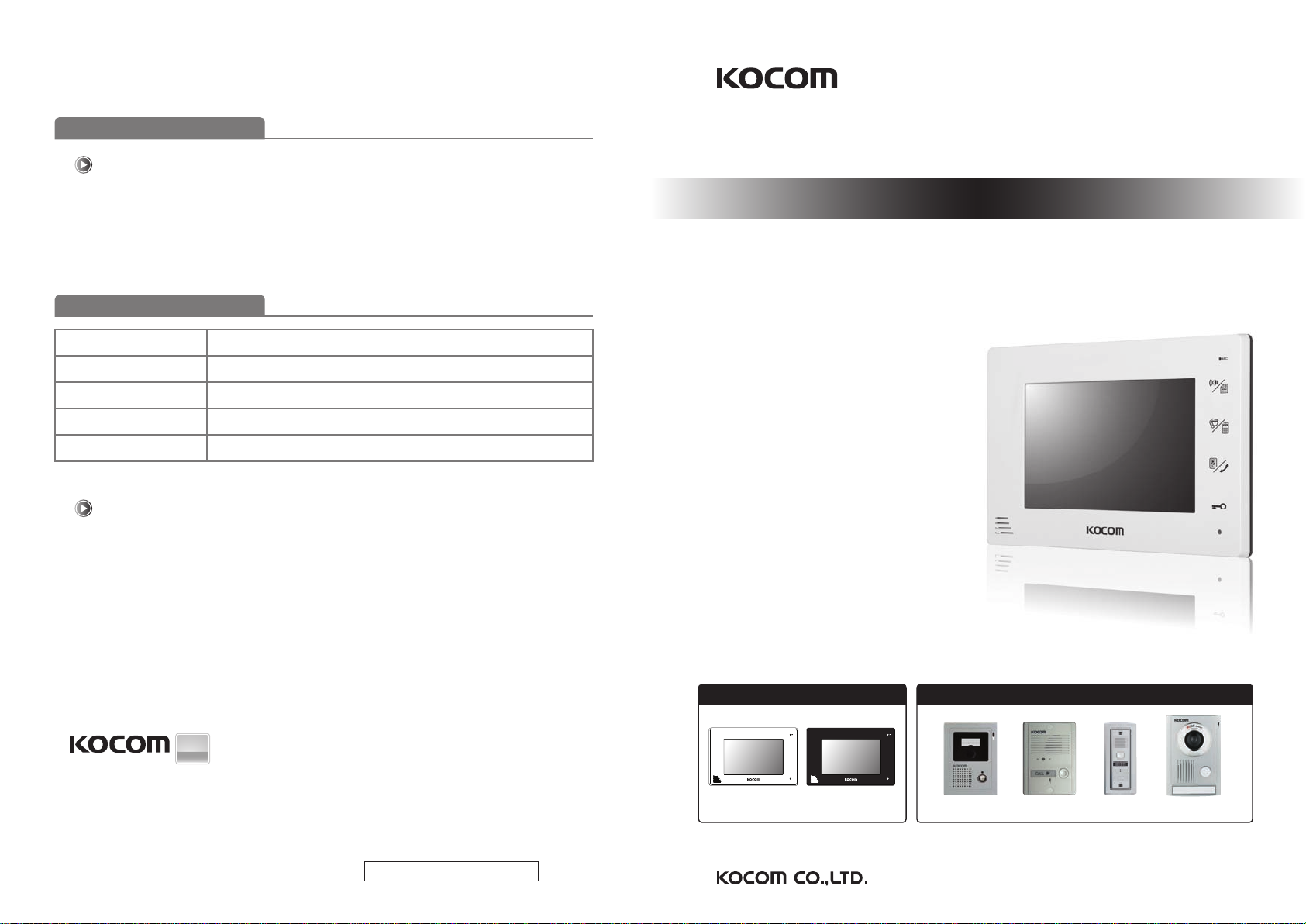
Videophone
·This product is designed as a home videophone and cannot use continuously like monitor camera.
·If there is temperature difference between inner part of camera and surrounding, dew condensation occurs on camera lens and may disturb image.
If dew condensation is removed from camera lens, image quality recovers.
·White LED light examination range is narrower than camera shot range at night, so there is less amount of light at night than day.
So it is difficult to see the face in low illumination condition due to noise increase on screen, but it is not from defect.
·Monitor screen (liquid crystal panel) is not in defect when some pixels always light or black out.
·Please install monitor and camera over 5cm away. Also, avoid installing at a place with too much noise, because too much noise around camera causes phone call inferiority.
·Do not place an object within 20cm in front of monitor. It causes phone call inferiority, especially because microphone is installed at the top of monitor.
·If strong light such as sunlight flows into camera module, screen saturation (or strange mark) and image shaking might occur.
·This is not a defect, so please do not install camera where a direct ray of light do not flow if possible.
Things You Need to Know
·In some cases there is occurrence of product destruction, malfunction, noise mixing and picture quality deterioration due to mixing of other tool’s induced
voltage or thunder with communication wiring of monitor/camera, monitor/extended monitor.
Do not wire with power line such as outdoor wiring or AC power, or phones and other tools.
·You cannot use it if you incorrectly wire the AC voltage between monitor/camera, monitor/extended monitor. Call the store or agency where you purchased
this product and consult to solve the problem.
Beware that unfixable damage might be caused due to authorizing AC voltage on communication wiring of monitor/camera, monitor/extended monitor.
·Do not ever disjoint this product. It may cause electrocution accident when touching high-voltage circuit inside this product.
·Outside power authorizing this product must be confirmed of product description and use rated voltage. Beware that if higher voltage is authorized, unfixable
damage might be caused due to product destruction.
·Power must be connected to domestic voltage (product rated voltage) consent or interior wiring.
If connected to other motive power or inverter-type power, product destruction, noise mixing, and picture distortion may occur.
·Do not drop this product. Glass is used for monitor and might break, or cause other circuit inferiority.
In such case, immediately turn down the power switch, and call to consult agency or store in which this product was purchased.
·If installed near transmission antenna such as broadcasting station, electric wave may mix and cause picture distortion or voice mixing.
·Avoid installing near tools with strong electromagnetic waves such as microwaves and cell phones, or it may cause picture distortion.
·Do not install monitor in following places.
① Above or around water heater, rice-cooker, heater ② Place exposed to direct rays of the sun ③ Place with temperature below 0'C such as cold store
④ Place with high humidity such as bathroom, washroom, heated room
⑤ Place with a lot of gas, dust, smoke ⑥ Dangerous place with sprays of water or chemicals
·Do not wipe with insecticide, drugs or chemicals such as thinner and alcohol, or it may damage
the surface of this product.
·Beware of occurrence of image quality deterioration or malfunction from cause of humidity due to
penetration of chemicals or water into camera’s urea resins.
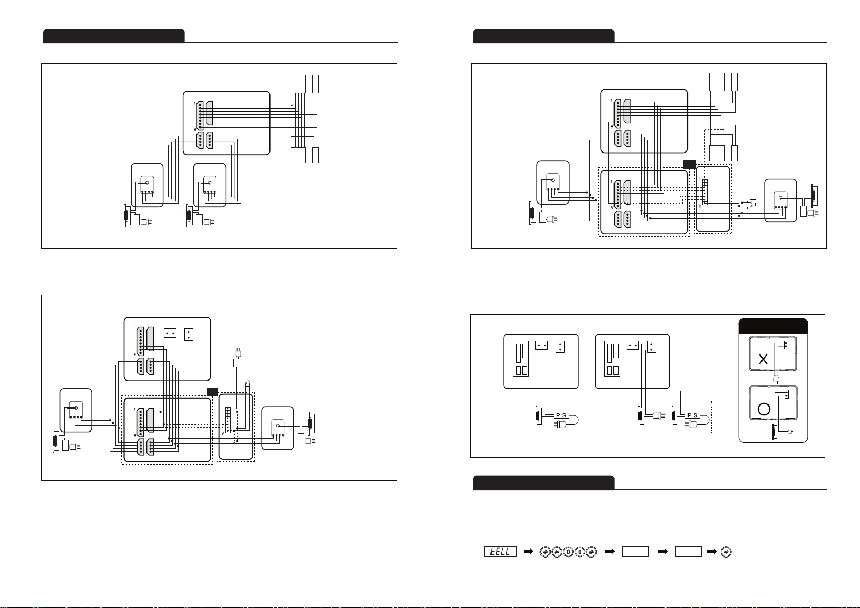
·As in the picture, it prevents temperature difference of camera (outside) and monitor (inside), and
removes dew condensation caused by humidity of camera window.
·Camera must be installed when wall cement is completely dry.
·When product is installed in winter below -5'C, wait for approximately 2 hours to connect. Dew formation
in monitor and camera due to temperature difference inside and outside may cause product defect.
·Avoid installing monitor and camera in place directly exposed to heat or where gas noxiousness is
highly occurring.
Cautions
Stop up P.V.C pipe using
adiabatic substances, to
prevent air circulation
Tubing Box Monitor
Pipe
Camera
(Outdoor, Door)
32

Components of product
Name and Functions of each part
Components of product
Name and Functions of each part
Specifications
54
4 Pin cable for camera
2 Pin cable for monitor door opener (DC)
4P×2
2P
■ Wire■ A Wall hanger frame
■ The front side ■ The back side
■ Monitor
4×12mm 4ea3×8mm 1ea
① Power switch : Use by turning AC power ON / OFF.
② Monitor screen (LCD) : Output of image sent from camera.
③ Speaker
④ [Talk/Menu] button
⑤ [Guard/Lobby] button
⑥ [Door/Interphone] button
⑦ [Door Open] button
: Door Open function during talking with visitor.
⑧ Brightness adjustment volume :
Adjusting LCD screen brightness to use.
⑨ Call volume adjustment switch : Adjusting call sound in
3 steps[high, medium, low] to use. (In shipment : [medium])
* Cannot adjust call sound to“none”.
⑩ Speaking volume adjustment switch : Adjust speaking volume
transmitted from camera to monitor in 3 steps [high, medium,
low]to use. (In shipment : [medium])
⑪ Camera 1 terminal : Connects camera 1 with 4 wire polarity.
⑫ Camera 2 terminal : Connects camera 2 with 4 wire polarity.
⑬ Program write
⑭ Main line port from lobbyphone.
⑮ Door2 - DC door switch terminal : Connects (Camera2) DC door switch.
Door1 -AC/DC door switch terminal
: Connects (Camera1) AC/DC door switch.
Power input section : Input power and fix power cord.
① Camera section :
Converts camera surroundings to visual signal and deliver to monitor.
② Speaker
③ Microphone
④ Call button : Push this button for output of call sound from monitor.
⑤ Monitor connection wire : 4 wires by polarity
Blue : Vcc , Yellow : Ground , Red : Audio , White : Video
■ Screw for fixing monitor
2 Pin cable for monitor door opener (AC/DC)
2P
8 Pin cable for multi-home main wiriong
8P
1
2
13
14
12
11 15 17
16
8 9 10
3
16
17
■Door Camera components
Screws for fixing main
body on the wall
Screws for fixing camera
to main frame supporter
4×10mm
4×10mm
4×16mm
2.6×6mm
Screws for fixing main
body on the wall
Screws for fixing camera
to main frame supporter
4×25mm
4X8mm
[KC-MC24]
Finishing rubber
Main body
supporter
Main body
supporter
Main body
supporter
[KC-MC30]
[KC-MC20]
Main body
supporter
or
Screw for fixing
camera main
body supporter
Screw for fixing
camera
3X5mm
2×8mm
Screw for fixing
camera
Screw for fixing
camera
“L”wench
Screw cap
[KC-C60]
Upward adjusting
supporter for lens angle
Lens
Speaker Call button
Lens
Speaker
Call button
Lens
Speaker Call button
Lens
Speaker
Call
button
■Camera (KC-C60)
①
Model number
Power Source
Power Consumption
Operating Temperature
Communication System
LCD
Wiring
Mount Type
Dimension
Camera connection
AC 100V-AC240V 50/60Hz DC 15V±10%
Stand by 2.5W, Max 13W Stand by 2.5W, Max 13W
0℃ ~ +40℃
Handsfree type
7" Digital LCD (NTSC / PAL Auto switching)
Camera : 4 wire (Polarity)
AC/DC Door : 2 wire
DC Door : 2 wire
Wiring lines of multi-home main line : 8 wire
Surface mount
222 (W) × 144 (H) × 33 (D) mm
KC-MC24, KC-C60, KC-MC20, KC-MC30
Power Source
Power Consumption
Operating Temperature
Dimension
Angle of Lens
DC 12V±1V (Power from Monitor)
Max 2.5W
-10℃ ~ +50℃
95 (W) × 127 (H) × 34 (D) mm
120。
KCV-A376 KCV-D376
Model number KC-C60
MONITOR
DOOR
CAMERA
4
5
6
7
②
③
④
⑤

Program
write
Camera installation
76
Installation location
Product connection diagram
■ Monitor installation location
■ Caution of camera installation
∙Standard monitor installation height
is about 1,500mm where screen
center is at eye level.
In this case, wall-hanging metal
center (center of piping) is 1,450mm
above ground level.
∙Standard installation height
■ Camera installation location
∙Camera installation in height Standard
camera installation height is when
lens is about 1,400mm above the floor.
In this case, camera stack center
(piping box) is above 1,390mm above
ground level.
∙Standard installation in height
∙Avoid installing camera exposed to direct ray of light (and sun).
∙Beware backlight and darkness of visitor’s face, which makes identification difficult.
∙Avoid installing camera in places such as the following picture.
(1) Place illuminating sky as background
(2) Place with white wall reflecting direct ray of light
(3) Place with direct ray of light
1) Remove wall-hanger bracket metal behind monitor.
2) Install wall-hanger bracket metal on 1 type box or wall with attached Vis.
3) Connect wiring to monitor back terminal referring to product connection diagram.
4) Hang monitor on wall-hanging metal, and fix monitor on wall- hanger bracket metal
using attached Vis.
5) Plug monitor’s power plug into consent and check to see if the power switch is [ON]
on the left side of monitor.
■ Directly connecting cut-off power cord with power wire
1) Do not do such electric work on your own. Installing product in this way
requires reliance on electric installation man with electric work license.
2) Insulate with insulating tape while cutting off power cord and connecting with power
wire so electric wire metal does not expose. Contact between exposed electric wires
cause fire or electric shock accident.
3) Such electric work requires connection after interception of supplied power.
※The above angel of view is based on the KC-MC24 camera.
The numbers very according to the type of camera.
■Monitor installation
■Name of each connection port
DC Type
Power cord
ADAPTOR
GND
VOICE 1
VOICE 2
VIDEO INPUT
DATA
PAB X
DATA-PABX
VIDEO OUT
Extention Monitor

Wiring diagram
98
■Door lock connection
※Caution of Door Lock
Monitor Monitor
Door 2 : DC Door Lock
(Camera 2 door open)
Door 1 : AC or DC Door Lock
(Camera 1 door open)
■Multi-home main wiring
■Single house wiring
①GND
②Voice 1
③Voice 2
④Video input
⑤Data
⑥PABX
⑦Data-PABX
⑧Video out
Video input
Video out
WIRING
POWER LINE : IV 1.2Ø
VOICE/DATA/PABX : IV 0.8Ø
VIDEO : COAXIAL CABLE 5C-2V
Monitor
Monitor
①Power
②GND
③Voice
④Video
Door camera
①GND
②Voice 1
③Voice 2
④Video input
⑤Data
⑥PABX
⑦Data-PABX
⑧Video out
Monitor
①Power
②GND
③Voice
④Video
Door camera
①GND
②Voice 1
③Voice 2
④Video input
⑤Data
⑥PABX
⑦Data-PABX
⑧Video out
Monitor
①+17V
②GND
③Voice 1
④Voice 2
⑤Data
⑥PABX
⑦Data-PABX
⑧Chime-bell
Interphone
①+17V
②GND
③Voice 1
④Voice 2
⑤Data
⑥PABX
⑦Data-PABX
⑧Chime-bell
Interphone
①Power
②GND
③Voice
④Video
Door camera
①~④
CAM 1
①~④
CAM 2
①~④
CAM 2
1
4
1
4
Wiring diagram
Password change
■Multi-home Ex_monitor or interphone connection
WIRING
POWER LINE : IV 1.2Ø
VOICE/DATA/PABX : IV 0.8Ø
VIDEO : COAXIAL CABLE 5C-2V
Monitor
MAIN
SUB
1
4
1
4
1
4
1
4
Interphone
※Caution
1. (Multi House) In case of connecting Sub Monitor and Interphone, do not connect DATA line.
2. (Single House) In case of connecting Sub Monitor and Interphone, additional lines to connect are GND, INTERNAL LINE, and DATA PABX.
3. (Single & Multi House) When you connect Sub Monitor or Interphone, set their ID as‘0000’and power off and on to reset.
①~④
CAM 1
Option Option
DC Door
opener
P
S
①~④
CAM 2
DC Door
opener
P
S
Monitor
MAIN
SUB
1
4
1
4
1
4
1
4
※In case of a single house application, an extra 17V(±1V) adaptor is necessary for the extended interphone.
or
DC Door
opener
P
S
DC Door
opener
P
SDC Door
opener
P
S
(Password change function is only available during the call with house.)
Pressing“ # # 0 0 #”during the call with house“, - - - - ”is displayed.
Input new password and press“ #”button.
e.g) When register passward as ‘2222’. (It should be 4 digits)
[Communication state] [Password input mode]
2222
[Password] [End]
----
[Hold]
Video input
Video out
Interphone
①~④
CAM 1
Option Option
DC Door
opener
PS
DC17±1V
CHIME-BELL
Option
P
S
1
4
1
4
or
Chime
-bell
Option

Press [Guard/Lobby]
button to call
Guard Room.
Instructions for operation
1110
◆ Visitor call from door camera
◆ To monitor outside of the door using monitor screen
◆ To monitor the lobby using monitor screen :
Press and hold [Guard/Lobby] button for 2 seconds to see lobby image (Image/Incoming voice : 8 second)
Visitor presses Call
button, and call is
forwarded to monitor.
Press [Door/Interphone] button
to display door camera to screen
(View time : 1 minute).
Press [Talk/Menu] button
and the call is connected.
(Talking time : 3 minute)
Call is completed when pressing [Talk/Menu]
button one more time. Pressing [Door Open]
button will open the door and the call is
automatically completed after 5 second.
Monitor speaker rings the
calling sound, and monitor
displays the visitor
(View time : 30 second).
Press [Talk/Menu] button
and the call is connected
(Talking time : 3 minute).
Call is completed when pressing
[Talk/Menu] button one more
time. Pressing [Door Open] button
will open the door and the call
is automatically completed after
5 second.
H
e
l
l
o
Instructions for operation
◆ Internal call & communication
Press and hold
[Door/Interphone] button
for 2 seconds.
MONITOR A MONITOR B
Additional monitor rings the
calling sound. Press [Talk/Menu]
button to connect the call
(Talking time : 3 minute).
Press [Talk/Menu] button
one more time to complete
the call.
◆ When visitor calls from lobby
Visitor calls the
house to visit by
pressing the house
number from lobby.
Monitor speaker rings the
calling sound, and monitor
displays the visitor
(View time : 30 second).
Press [Talk/Menu] button
and the call is connected
(Talking time : 3 minute).
Call is completed when pressing
[Talk/Menu] button one more
time. Pressing [Door Open] button
will open the lobby door and
the call is automatically completed
after 5 second.
H
e
l
l
o
◆ When call comes from Guard Room
Guard Room calls
the house by pressing
the house number.
Monitor speaker rings the
calling sound, and call is
connected when pressing
[Talk/Menu] button
(Talking time : 3 minute).
Press [Talk/Menu] button
one more time to complete the call.
◆ When make call to Guard Room
Call is connected when
Guard Room answers
the call.
(Talking time : 3 minute)
Press [Guard/Lobby] button
one more time to complete the call.
Definition of Menu Mode Button
UP Button : [Guard/Lobby] Button
DOWN Button : [Door/Interphone] Button
Confirm Button : [Door Open] Button
MENU Setting
To enter to Menu for setting, turn off and on the monitor and immediately in 1 minute push Talk/Menu button for more
than 2 seconds. Press Talk/Menu button shortly one more time to complete the setup.
1. ID Setting :
Pressing <Confirm> button will move to House Number, and House ID can be changed using <UP/DOWN> button.
2. CAM / LB Setting : Need to change setting according to the door camera and lobbyphone model.
3. CAM1 VIEW TIME Setting : Able to set CAM1’s VIEW TIME to 1 MIN or 3 MIN.
4. CAM2 VIEW TIME Setting : Able to set CAM2’s VIEW TIME to 1 MIN or 3 MIN.
5. MIC : Able to change the MIC volume between levels 1-5 level (audio volume to the receiver).
6. MODE Setting : Identified by OLD and NEW version of interconnected Lobby Phone.
■OLD MODE : Able to set House ID Number up to 1~63, 100~963, 1000~1963, 2000~2963, and 3000~3963.
■NEW MODE: Able to set House ID Number continuously between 1~1599.
7. SYNC Setting : When connecting Lobby Phone it can select the PAL/NTSC spec of the Lobby Phone
8. INIT Setting : Initialize the setting of Menu Setup.
1. ID
2. CAM C60 LB C100
3. CAM1
4. CAM2
5. MIC
6. MODE
7. SYNC
8. INIT
0001
VIEW TIME 1MIN
VIEW TIME 1MIN
3
OLD
PAL
NO
This manual suits for next models
1
Table of contents
Other KOCOM Telephone manuals

KOCOM
KOCOM KIV-212 Instruction Manual

KOCOM
KOCOM KIV-101EV User manual

KOCOM
KOCOM KCV-544SD User manual

KOCOM
KOCOM KCV-A374SD User manual

KOCOM
KOCOM KCV-A510R User manual

KOCOM
KOCOM KCV-464 User manual

KOCOM
KOCOM KCV-D372(D1) User manual

KOCOM
KOCOM KIV-102 Instruction Manual

KOCOM
KOCOM KCV-D372 User manual

KOCOM
KOCOM KCV-A510R User manual

KOCOM
KOCOM KCV-T701SM User manual

KOCOM
KOCOM KIV-101 Manual

KOCOM
KOCOM KCV-W354 User manual

KOCOM
KOCOM KCV-544 Manual

KOCOM
KOCOM KVR-A510 Reference manual

KOCOM
KOCOM KCV-A374SD User manual

KOCOM
KOCOM KCV-350 User manual

KOCOM
KOCOM KIP-120 User manual

KOCOM
KOCOM KCV-S701EB User manual

KOCOM
KOCOM KCV-504 User manual