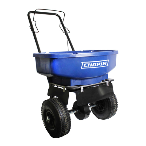
Bio-Logic 6333N User manual

PROFESSIONAL SPREADER Assembly / Operation Instructions / Parts
Please call 888-201-1193 if you are missing any parts, having trouble assembling, or have any questions regarding the safe
operation of this product.
DO NOT RETURN TO THE STORE
MODEL 6333N
Carefully Read These Instructions Before Use
IMPROPER USE OR FAILURE TO FOLLOW INSTRUCTIONS CAN RESULT IN PRODUCT FAILURE OR INJURIES. FOR SAFE
USE OF THIS PRODUCT YOU MUST READ AND FOLLOW ALL INSTRUCTIONS BEFORE USING.
- Do not allow anyone to operate the broadcast spreader without proper instructions
- Do not permit children to operate the broadcast spreader
- Wear protective eyewear and gloves when handling and applying lawn and garden chemicals
- Read the chemical label instructions and warnings for handling and applying the chemicals you plan to
spread – application settings provided are only a guideline
WARNING
013652 R0414
CHAPIN OUTFITTERS P.O.BOX 549 700 ELLICOTT ST. BATAVIA,NY 14021-0549 www.chapinoutfitters.com 888-201-1193

ASSEMBLY INSTRUCTIONS
Suggested Tools:
Wrench and/or Ratchet Set
1.5mm Allen Wrench
Pliers
Protective Eyewear
Approximate assembly time is 20-45 minutes
Full scale nuts and bolts
NOTE: Depending on model, this package may contain
additional hardware not needed for assembly.
M5 Nylon Locknut (1)
M6 Nylon Locknut (7) M6 x 55mm Hex Bolt (6) M6 x 45mm Hex Bolt (1)
M5 x 35mm Hex Bolt (1)
Spacer (4)
Flat Washer (1)
R- Pin (1) Cotter Pin (1) #8-18 x 1/2
read-Forming Phillips
Screw (1)
P-Clamp (1)
End Cap (2)
Hand Grip (2) Bushing (2)
CHAPIN OUTFITTERS P.O. BOX 549 700 ELLICOTT ST. BATAVIA, NY 14021-0549 www.chapinoutfitters.com 888-201-1193

Step 1:
Attach the right Frame leg and the le Frame leg to the Frame
Body using 2 spacers, (2) M6X55mm hex bolts and (2) M6 Nylon
locknuts per frame leg. Aer the frame legs have been attached,
place the two End caps onto the bottom of both frame legs. DO
NOT TIGHTEN DOWN COMPLETELY.
NOTE: Use bottom hole pattern on legs if equipped.
Step 2:
Slide bushings into the holes on
the hopper frame from outside
of the frame.
Step 3:
Insert Axle into Tire as shown and secure using (1) M6 x 45mm Hex
Bolt and (1) M6 Nylon Locknut. Take note of hole locations on
Axle, to ensure correct orientation.
Hole at top
CHAPIN OUTFITTERS P.O. BOX 549 700 ELLICOTT ST. BATAVIA, NY 14021-0549 www.chapinoutfitters.com 888-201-1193

Step 4: Install the Axle/Drive Shaft
a. Slide the Drive sha through one side of the
hopper frame
b. Slide gearbox onto axle/drive sha (make sure
“FRONT” is facing front of frame as shown) and
align middle hole with gearbox
c. Slide through the other side of the hopper
frame. Assemble M5 x 35mm Hex bolt to Axle/
Gearbox and secure with M5 Nylon Locknut.
Step 5:
Attach non-drive Wheel onto exposed end of Axle and secure with Flat Washer & Cotter Pin. Slide
the Flat Washer onto the Axle until it makes contact with the Wheel, and then slide the Cotter Pin
into the hole at the end of the Axle.
Additional Notes:
Drive Sha: Hole Near Middle should be closer to the right wheel so that the gear box is centered.
Bend
M5 x 35mm Hex bolt
CHAPIN OUTFITTERS P.O. BOX 549 700 ELLICOTT ST. BATAVIA, NY 14021-0549 www.chapinoutfitters.com 888-201-1193

Step 8:
Assemble Handle Tube to Frame Legs by sliding
Handle Tube into the gap between the two parts
and using (2) M6X55mm bolts and (2) M6
Nylon Locknuts to connect the parts together.
Handle orientation is important (see image).
Finish tightening frame legs to the frame body.
Step 6:
Look inside hopper. Insert R-pin
into hole in impeller sha.
Step7:
A portion of the Handle will be preassembled as shown. Carefully remove the
(2) M6 Hex Nuts, while holding the rest of the Handle Assembly together.
Install opposite Handle onto the
exposed (2) M6 Hex Bolts, and re-
secure the (2) M6 Hex Nuts.
IMPORTANT: You must remove the
R-pin when applying salt or ice melt.
CHAPIN OUTFITTERS P.O. BOX 549 700 ELLICOTT ST. BATAVIA, NY 14021-0549 www.chapinoutfitters.com 888-201-1193

Step 9: Attaching the Gate Control Rod
a. Slide gate control lever forward and attach hook at bottom of
rod to spring at hopper base
b. Attach gate control rod to upper screw on gate control by
removing the screw rst, attaching the rod, and then
re-attaching the screw
Step 10:
Both Hand Grips slide onto both the le and right
handle bars. e Grips should Slide right on.
CHAPIN OUTFITTERS P.O. BOX 549 700 ELLICOTT ST. BATAVIA, NY 14021-0549 www.chapinoutfitters.com 888-201-1193

Replacement Parts
Ref.# Qty Part No. Description
1 1 6-9008 Hopper Base Assembly
2 1 6-9010 Gear Box Assembly
3 1 6-9009 Drive Shaft w/2 bearing
4 1 6-9012 Gate Control Assembly
5 1 6-9013 R Pin
6 1 6-9014 Impeller
7 1 6-9015 Wheels w/hardware
8 1 6-9016 Handle Grips
9 1 6-9017 Hardware Bag
10 1 6-9001 Grate
* 1 6-9000 Rain Cover
* Not Shown
CHAPIN OUTFITTERS P.O. BOX 549 700 ELLICOTT ST. BATAVIA, NY 14021-0549 www.chapinoutfitters.com 888-201-1193
8
1
2
4
6
9
3
7
10
5

START RESTART RESTART
RESTART RESTART
SHUT OFF HERE SHUT OFF HERE
SHUT OFF HERE SHUT OFF HERE
Sample Spread Pattern
• Whennishedspreadingemptyhopperofanyremainingmaterial.
• oroughlywashspreaderandallowtodrybeforestoring.
• Gearsarepermanentlylubricatedatthefactory.DONOTopenthegearboxatanytimeasdebrismayenter
and interfere with functionality.
• Whenusingrocksaltandice-meltproductsbesuretoemptythehopperuponcompletionofspreadingeach
time you use it. ese materials may reconstitute back into a solid block overnight with humidity. ey can also
damage metal parts if exposed for extended periods of time.
STORAGE AND MAINTENANCE
Scotts 2 2.5 3 3.25 3.5 4 4.75 5 5.5 6 7 8 9 10 11 12 13 14 15
Chapin 9 10 11 12 13 14 15 16 17 18 19 20 21 22 23 24 25 26 27
All Season Residential & Professional Push Spreader Application Conversion Chart
All Season Residential &
Professional General Application
Guidelines
Weed Control
Fertilizer
Grass Seed - Overseeding
Grass Seed - New Lawn
Salt & Ice-Melt
10-12
12-16
16-20
21-27
28-30
APPLICATION CHART
•Besuregatecontrolisintheclosedposition.
•Determineappropriatesettingformaterialbeingusedbyreadingthesuggestedsettingonthematerial’sbag
AND/ORbyreferencingtheapplicationchartonyourspreader’scontrolpanel(Chartsprovidedareonlyguidelines.
Besuretoreadtheinstructionsonthebag/boxofthematerialyou’respreadingtoidentifyaccuratesettingneeded)
•SetthedialtothedesiredsettingImportant Note: Do not adjust dial with gate open.
is will alter the accuracy of gate settings and cause parts to break.
•Tobeginspreading,startwalking(about3mphpace)andpullthegatecontroldowntoopengate.
•Tostopspreadingsimplypushgatecontrolupandthegatewillclose.
GENERAL OPERATING INSTRUCTIONS
CHAPIN OUTFITTERS P.O. BOX 549 700 ELLICOTT ST. BATAVIA, NY 14021-0549 www.chapinoutfitters.com 888-201-1193
Table of contents
Popular Spreader manuals by other brands

Neilsen
Neilsen CT2215 Original instructions

Buyers
Buyers SaltDogg 1470601SSE installation instructions

Toro
Toro Topdresser 2500 Operator's manual
Bearcat
Bearcat BC-2016/CRC instruction manual
Trynex International
Trynex International SnowEx SL-80 Owner's/operator's manual

DÖNDER
DÖNDER CGSA Series user manual
PERFORMANCE ADVANTAGE COMPANY
PERFORMANCE ADVANTAGE COMPANY K5024 installation instructions
Agri-Fab
Agri-Fab 45-0187 owner's manual

ROLLAND
ROLLAND ROLLFORCE instruction manual

Geotech
Geotech SP 31509 Assembly & operating instructions
The Handy
The Handy THDS instruction manual

Buyers
Buyers SaltDogg SHPE2000 installation instructions
