manuals.online logo
Brands
  1. Home
  2. •
  3. Brands
  4. •
  5. Buyers
  6. •
  7. Spreader
  8. •
  9. Buyers SaltDogg SHPE2000 User manual

Buyers SaltDogg SHPE2000 User manual

1
9049 Tyler Blvd. • Mentor, Ohio 44060
Phone (440) 974-8888 • Fax (440) 974-0165
Toll-Free Fax 800-841-8003 • saltdogg.com
Installation Instructions
—continued inside
SHPE2000, SHPE2000RED, SHPE2000YEL
Series SaltDogg®Electric Drive Poly Hopper
Spreader
2.0 cubic yards
U.S. PATENT 9,562,333
Serial Number 21000 and Above.
Table of Contents
General Information .....................................................................1
Safety Precautions .......................................................................1
Warranty Information ...................................................................2
Installation Instructions ............................................................ 2-4
Spreader Operation .....................................................................5
Spreader Maintenance.................................................................5
Repair Parts & Drawings .........................................................6 -10
General Information
Spreader models:
• SHPE2000- spreader with standard length chute
• SHPE2000X- spreader with extended length chute
Overall Length: 96 inches
Overall Width: 48 inches
Overall Height: (installed): 41.5 inches
Empty Weight: 5
60 lbs. (standard chute), 564 lbs. (extended chute)
Capacity Struck: 2.0 cu. yd.
Average Installation Time: 3 hrs.
Vehicle Requirements
• 3/4 or 1 ton pick-up truck above 8500# GVWR.
• 135 AMP or higher alternator is recommended.
Materials Recommended to Spread
SHPE2000 SALTDOGG SPREADER WARRANTY INFORMATION
This warranty replaces all previous warranties and no employee of this
company is authorized to extend additional warranties, or agreements, or
implications not explicitly covered herein.
Buyers Products Company warrants all parts of the product to be free
from defects in material and workmanship for a period of two (2) years.
Parts must be properly installed and used under normal conditions.
Normal wear is excluded.
Any part, which has been altered, including modifications, misuse, acci-
dent, or lack of maintenance will not be considered under this warranty.
The sole responsibility of Buyers Products Company under this warranty
is limited to repairing or replacing any part(s), which are returned, pre-
paid, 30 days after such defect is discovered, and returned part(s) are
found to be defective by Buyers Products Company.
Authorization from Buyers Products Company must be obtained before
returning any part. The following information must accompany defective
parts returned to Buyers Products Company: RMA #, spreader model,
serial number, date installed, and distributor from whom purchased.
Buyers Products Company shall not be liable for damage arising out of
failure of any unit to operate properly, or failure, or delay in work, or for
any consequential damages. No charges for transportation or labor per-
formed on any part will be allowed under this warranty.
CAUTION
Do not overload vehicle beyond the vehicle’s GVWR or GAWR.
Check vehicle's load rating certification sticker for maximum
vehicle capacity.
Average Material Weights
Materials to use Weight (pounds per cubic yard)
Fine Salt-Dry 2,250
Coarse Salt-Dry 1,431
Sand/Salt up to 50/50 Mix-Dry 2,700
Note: To calculate the total spreader weight (including ice
control material), add the empty spreader weight plus the ice
control material and spreader accessories.
2
Safety Precautions
WARNING
Observe the following Safety Precautions before, during and
after operating this spreader. By following these precautions and
common sense, possible injury to persons and potential damage
to this machine may be avoided.
1. Read this entire Owners Manual before operating this
spreader.
2. Read all safety decals on the spreader before operating.
3. Check to make sure all safety guards are securely
mounted into place before operating this spreader.
4. Verify that all personnel are clear of the spreader
spray area before starting or operating this spreader.
5. Do not over-load your vehicle beyond payload limits.
If there are any questions, contact the vehicle manufacturer.
6. Do not adjust, clean, lubricate or unclog material
jambs without first turning off the spreader.
7. Do not climb on or in the spreader during operation.
Do not ride on the spreader while the vehicle is in motion.
8. Make sure the spreader is securely fastened to the vehicle in
accordance with this manual.
9. Do not operate a spreader that is in need of maintenance or
repairs.
10. Always disconnect the battery before removing or replacing
electrical components.
Installation Instructions
1. Mounting the Spreader onto the Vehicle:
A. Remove the tailgate from the vehicle.
B. Check truck’s bed for all kinds of sharp debris
or foreign objects. They can cut and seriously damage
poly hopper.
C. Lift spreader using tie downs (fig. 1), or using fork lift.
D. Lower spreader into the truck bed.
E. Center the spreader from side to side on the vehicle.
F. Attach the Chute Assembly to the spreader. First, hook the
Chute to the spreader by openings in the Chute’s handle.
Fig. 1
Then rotate the Chute into operating position and lock using
two spring latches.
G. Slide spreader towards front of the truck leaving adequate
space between chute and truck (2-3 inches). Measure
the distance from the front of the truck bed to front of the
hopper’s front legs. Fabricate spacer to fit between front of
the spreader and front of the bed per Fig. 4 and Fig. 5
USE ALL TIE-DOWNS
TO LIFT SPREADER
Fig. 2
LOCK CHUTE IN PLACE
USING LATCHES ON BOTH SIDES
LATCH #B2598SSC
Fig. 3
3
H. Secure spreader using four ratchet straps as shown in
Fig. 6. Tighten straps evenly to secure spreader in the middle
of the truck box.
Fig. 4
Fig. 5
Verify with the vehicle’s manufacturer that the factory
installed anchor points are designed for tie-down such
load. Inspect straps and hardware after each time
spreader is loaded. Tighten straps and hardware if
necessary.
2. Install Control Box & Vehicle Wiring Harness (Fig. 7).
NOTE: THIS IS A WIRE GROUND ELECTRICAL SYSTEM! NO
CONNECTIONS TO TRUCK'S FRAME OR BODY ALLOWED!
ALWAYS DISCONNECT BATTERY BEFORE ATTEMPTING
TO INSTALL ELECTRICAL COMPONENTS ON YOUR
VEHICLE.
To insure good performance of your spreader, check the
condition of truck’s electrical system. Using digital voltmeter,
check alternator and battery voltage. The voltage reading should
fall between 13.6 and 15.3 volts with engine running, head lights
and heater fan turned on. If voltage reading falls out of this range,
check and adjust your electric system.
A. Lay out a wiring path for the Vehicle Wiring Harness.
Connect the Wire Harness smaller terminal to the Chute’s
harness, large terminal to the Hopper’s harness. Drill all
necessary holes or use existing ones to pass the round
CAUTION
DO NOT MOUNT CONTROLLER IN WAY OF AIR BAG DEPLOYMENT
WARNING
Do not drill holes into fuel tanks, fuel lines, through electrical
wiring, etc that may be damaged by drilling.
WARNING
Use extreme caution when working around an operating vehicle
engine.
connector into the trucks cab. Secure harness to truck’s
frame.
B. Mount the Controller in a convenient location in the truck cab.
Do not mount controller directly in front of the heat vents. Allow
ample air space around controller. Protect controller from water,
dirt and dust.
C. Apply dielectric grease or similar compound to
connectors before assembly. Connect the round
connector on the wire harness to the round connector on the
controller.
D. Lay out path for the power cable in the truck’s engine
compartment. Drill hole in the firewall or use an existing one to
pass the wire harness. Passing the power cable from inside of
the cab to the battery is recommended to protect the large high
amperage connector. Do not route the power cable close to
exhaust system!
E. Connect power cable connector to controller.
F. Connect the power cable ring terminals to the truck battery
(fig. 7).
ATTENTION
Do not connect black (negative) wire to any part of vehicles
frame. Connect this terminal to battery’s negative terminal.
12.0
16.0
2" X6"
TO FIT BED WIDTH
TO FIT BETWEEN
SPREADER AND
FRONT OF THE BED
Fig. 6
4
Fig. 7
2. When filling hopper use the supplied screen to prevent large
chunks of material and debris in the material to get into hopper
and cause damage.
3. Material must never be left in hopper for an extended
period of time. Material will absorb moisture, bind, harden
and could prevent spreader from proper operation or may
damage the spreader. Empty and clean after each use.
4. The SHPE2000 spreader is equipped with a dual
independent speed controller with warning indicators and a
vibrator switch. To start the spreader, press the ON-OFF switch.
Switch will illuminate. Rotate knobs to desired positions to
activate Auger and Spinner. Press Pause button to stop Auger
and Vibrator. To restart Auger and Vibrator press Pause button
again. Auger will start with same speed.
5. To activate the vibrator press the vibrator switch ON. Vibrator
switch will illuminate.
6.
To stop the spreader, push ON-OFF switch to OFF position.
Controller Warnings
Check controller instruction sheet for latest controller updates
and troubleshooting codes. Controller instruction sheet is inside
controller shipping box.
IMPORTANT! INSTALLER, DO NOT DISCARD CONTROLLER
INSTRUCTION SHEET. STAPLE SHEET TO SPREADER
MANUAL AND GIVE TO END USER!
Note: To unclog auger manually, first remove the chute. Apply
1¼" open wrench on auger’s nut. Turn auger counterclockwise
several times.
Note: Do not run the vibrator longer than 30 minutes with 15
minutes between runs to avoid overheating.
Thoroughly clean battery terminals. Make sure battery
terminals have no tarnish or corrosion.
DO NOT CONNECT WIRE HARNESS TO DAMAGED
OR CORRODED TERMINALS! IT MAY RESULT IN
OVERHEATING, LOST POWER AND POTENTIAL
CONTROLLER DAMAGE!
G. Attach utility light (optional) to spreader hopper in desired
location. Connect as shown in Fig. 7. Use utility light kit part
number 3018009.
H. LED spot light installation. Connect LED light’s positive
wire to harness brown wire. Verify with vehicle manufacturer if
your truck is “frame ground” or “switched ground” i.e. frame is
positive. In trucks with “frame ground” connect light’s negative
wire to truck frame. In trucks with “switched ground” find
negative conductor (battery negative terminal) and connect
light’s negative wire to it.
I. See controller instructions for latest updates and error codes.
Spreader Operation
1. Different materials absorb moisture at different rates and
some materials may not perform as desired. Substitution
of an alternative material may be necessary for optimum
performance.
3014199
3006724
3035933
CB120PB
3001379
BATTERY POSITIVE
BATTERY NEGATIVE
5
LOOSE WING NUTS
TO ROTATE SHIELD
HOLES FOR MOIST,
HEAVIER MATERIALS.
HOLES FOR DRY,
LIGHTER MATERIALS.
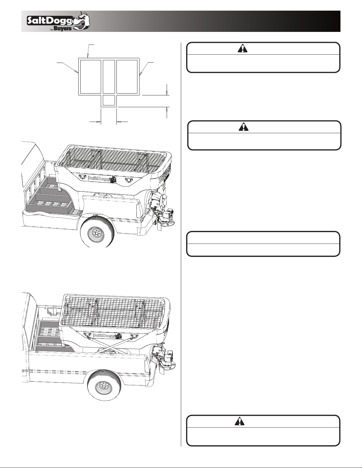
Material Flow Adjustments
Always use screen during spreader operation! Various
materials have different moisture absorption rate, some
materials may not perform as desired. Therefore, the
substitution of the alternate material may be necessary for
optimum performance.
SHPE2000 equipped with adjustable deflector located above
auger opening. To reduce gear motor load and amount of
material going in auger opening lover deflector. When using
more abrasive materials or materials with higher moisture
content raise deflector to allow easier access to auger opening.
Discharge opening equipped with sliding door. Close door when
transporting spreader, open door completely when spreading
materials. To access door, unlock and swing out chute. Undo
wing nuts on both sides of the trough, slide door in necessary
position, re-tighten wing nuts. Return chute on original position.
See Fig 8.
Spreader Maintenance
1. Wash spreader after every use. Make sure no material is left
under auger and/or inside trough.
2. Inspect and retighten fasteners after every 5-7 hours of
operation.
3. Lubricate bearing every 7-10 hours of operation using
general automotive grease.
4. Inspect terminals/connectors every time you disconnect
spreader from wire harness. Apply thin layer of dielectric grease
on terminals. If any tarnish/corrosion is found, clean terminals
and apply dielectric grease.
5. Use dielectric grease on all electrical connectors before an
electrical connection is made or after connector is disconnected
6. Grease and spray with lubricant Auger bearing after every 20
hours of use.
7. Empty the spreader of all ice control materials when not in
use. Wash out the spreader to prevent material builds up.
8. It is recommended to cover spreader with the tarp during
storage periods.
WARNING
Never remove spreader with material in hopper.
End of Season Maintenance
1.
Wash spreader. Make sure no material or residue is left in and
outside the hopper.
2.
Lubricate bearing using general automotive grease.
3.
Inspect wire harness, connectors for broken insulation, missing
components. Replace if necessary.
4.
Apply dielectric grease on all electrical connectors.
5.
Store hopper indoors, in a dry, cool place.
6.
Remove controller from truck. Store controller indoors, in a dry,
cool place.
7. Inspect wire near connectors. Check for broken or missing
insulation. Check for tarnished or corroded wires. Trim corroded
wires and replace connectors if necessary.
Summer Storage
1.
Apply dielectric grease or similar protective compound on all
electrical connectors & protect them with caps before storage.
2. Disconnect and remove speed controller from vehicle and
store it in dry and cool place. Protect controller from excessive
heat and moisture.
3. Clean hopper and trough from all kinds of debris.
4. Remove, thoroughly lubricate and reinstall trough bearing.
5. Protect hopper from excessive temperatures during
summer storage.
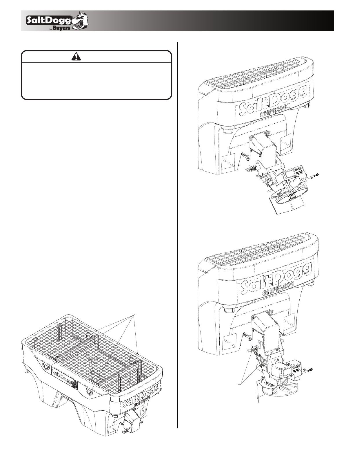
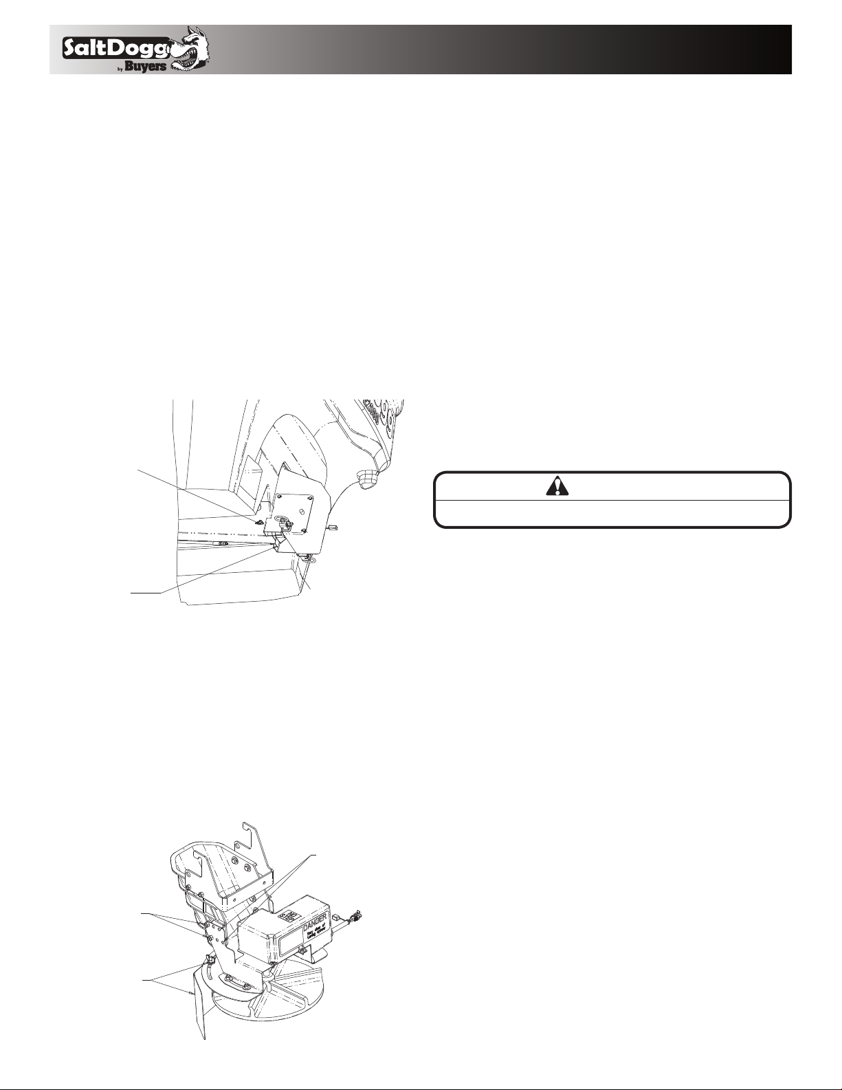
Spread Pattern Adjustment.
Spread pattern can be adjusted by changing spinner disc speed
on controller by turning Spinner knob to desired speed level
from 1 (low) to 9 (high). Direction of material spread can also be
adjusted by rotating shield on chute assembly. To rotate shield
lose 2 wing nuts, rotate shield in desired direction, and retighten
wing nuts. See Fig.9. Make sure that after adjustment, bracket
stays inside shield groove located on top of shield. In addition,
chute assembly can be adjusted to lighter (drier) and heavier
(more moist) materials. Use different holes on bracket for lighter
or heavier materials to have material drop on spinner disc
center. See Fig. 9.
WING NUT
SLIDING DOOR COMPLETELY
OPEN FOR SPREADING.
COMPLETLY CLOSE
FOR TRANSPORT.
Fig. 8
Fig. 9
6
Bills of Material Bills of Material
ITEM PART NO. QT Y. DESCRIPTION
13007526 1 CHUTE POLY. EXT. LENGTH
23006833 1 GEAR MOTOR 12 VDC. SPINNER
33007824 1RETAINER GEARMOTOR, CHUTE
4FWL031058008SS 3 WASHER, 5/16 LOCK SST
5
FCS031018063SS
3 SCREW, HHC 5/16-18 X 5/8 SST
63012393 1SPINNER, 14" POLY CW
73027699 1HANDLE, CHUTE
83007564 1 BRACKET, SHIELD SST
93007004 1SHIELD, SPINNER, SHPE1500
10 3007413 1 COVER, GEAR MOTOR, CHUTE
11 FWF038100007SS 16 WASHER, FLAT 3/8 USS SST
12 FCS038016100SS 10 SCREW, HHC 3/8-16 X 1 304 SST
13 FNE038016044SS 10 NUT, NYLOCK 3/8-16 X 7/16 SST
14 3007522 6SCREW, SHEET MTL #12x1.0 HEX WASHER
HD SST
15 3007113 1 PIN, CLEVIS, 5/16 X 2-1/2, .141 HOLE ZN
16 FPC013000100 1 COTTER PIN, 1/8 X 1, ZINC
17 3002631 1LABEL, "NO STEP"
18 3007844 1 DECAL, DANGER STAY CLEAR
19 3025065 1BUSHING STRAIN RELIEF
Repair Parts - Standard Chute Assembly Repair Parts - Extended Chute Assembly
1
2
3
4
5
6
7
8
9
10
11
12
13
14
15
16
17
18
19
20
1
2
3
4
5
6
7
8
9
10
11
12
13
14
15
16
17
18
19
ITEM PART NO. QT Y. DESCRIPTION
13025063 1 CHUTE POLY, SHPE STD. LENGTH
23033665 1BRACKET WELDMENT, CHUTE
33006833 1 GEAR MOTOR 12 VDC. SPINNER
4
3027699
1HANDLE, CHUTE
5FWF038100007SS 10 WASHER, FLAT 3/8 USS SST
6FCS038016125SS 8 SCREW, HHC-3/8-16 X 1.25 SST
7FNE038016044SS 8 NUT, NYLOCK 3/8-16 X 7/16 SST
8FWF031075006SS 3 WASHER, 5/16 SAE SST
9FCS031018063SS 3 SCREW, HHC 5/16-18 X 5/8 SST
10 3012393 1SPINNER, 14" POLY CW
11 3025067 1ENCLOSURE, GEAR MOTOR
12 3025065 1BUSHING STRAIN RELIEF
13 3001537 3 SCREW, S0CBHCS #10 X 5/8 SST
14 FNE010024024SS 3 NUT, ELASTIC STOP 10-24 SS
15 3007113 1 PIN, CLEVIS, 5/16 X 2-1/2, .141 HOLE ZN
16 3017444 1SHIELD, CHUTE
17 3014960 2 BOLT, 3/8-16 X 1 CARRIAGE SHORT NECK SS
18 3017356 2 WASHER, EXTERNAL TOOTH LOCK 3/8 SS
19 3025064 2
NUT, 3/8-16 WING, SST
20 3014994 1
PIN,COTTER,1/8IN X 1IN SST
7
Bills of Material
ITEM PART NO. QT Y. DESCRIPTION
1
3035920 1 HOPPER POLY 2 CU YD
3036867 1 HOPPER POLY 2 CU YD, RED
3036868 1 HOPPER POLY 2 CU YD, YELLOW
23024289 1TROUGH ASSEMBLY, SHPE
33007115 10 WASHER, FLAT 3/8 X 1.5 X.048 SST
4FWL038069009SS 10 WASHER, LOCK RHS-3/8 SST
5FCS038016075SS 10 SCREW, HHC-3/8-16 X 3/4 SST
63036561 2CROSS MEMBER WELDMENT
73022220 4TIE-DOWN WELDMENT
83036809 12 SCREW HHC-1/2-13 X 6.0 ZINC
9FWF050106010 12 WASHER, FLAT 1/2” SAE ZINC
10 FNE050013053 12 NUT, NYLOCK 1/2-13 ZINC
11 3007236 1COVER GEARMOTOR
12 FWL025050006SS 6 WASHER, 1/4 IN. SPRING LOCK SST
13 FCS025020075SS 6 SCREW, CAP 1/4-20 X 3/4 SST
Repair Parts-Hopper Assembly
ITEM PART NO. QT Y. DESCRIPTION
14 3007821 1STRAIN RELIEF BUSHING
15 3020713 1CONNECTOR, MALE, FEMALE
16 3022955_ 1 HOSEGREASE, 1/8 NPT, 36 IN LONG
17 H3309X2 1 CONNECTOR, FEM NPT TO FEM NPT 1/8 X 1/8
18 800 1 GREASE FITTING, 1/4 STD
19 4375 4 CLAMP, HOSE .4375, 9/32 HOLE
20 3007522 6SCREW, SHEET MTL #12x1.0 HEX WASHER
HD SST
21 3036037 1INVERTED VEE, SHPE2000
22 FCS038016100SS 2 SCREW, HHC 3/8-16 X 1 304 SST
23 FWF038100007SS 2 WASHER, FLAT 3/8 USS SST
24 FNE038016044SS 6 NUT, NYLOCK 3/8-16 X 7/16 SST
25 3007416 1 VIBRATOR 200 LBS 12 VDC
26 3036572 1MOUNT, VIBRATOR
27 9240132 1 DECAL #2, DANGER BEFORE SVCE
1
2
3
45
6
7
8
9
10
11
12
13
14
15
16
17 18
19
20
21
22
23
24
25
26
27
8
9049 Tyler Blvd. • Mentor, Ohio 44060
Phone (440) 974-8888 • Fax (440) 974-0165
Toll-Free Fax 800-841-8003 • saltdogg.com
3036575_A
Bills of Material
Repair Parts- Spreader
ITEM PART NO. QT Y. DESCRIPTION
1
3035921 1 HOPPER ASM. 2 CU YD POLY
3036869 1 HOPPER ASM. 2 CU YD POLY, RED
3036870 1 HOPPER ASM. 2 CU YD POLY, YELLOW
2 3034599 1 TOP SCREEN XD2000
3 66050 4 SNAPPER PIN, 1/4 X 2, YLW ZINC
4 3025070 1 CHUTE ASSEMBLY. STD LENGTH
5 3036574 1 HARDWARE KIT SHPE2000
6 3014199 1 CONTROLLER, SHPE, SALT DOGG
7 3006724 1 WIRE HARNESS, MAIN
8 3035936 1 KIT POWER CABLE REPLACES 3006842
9 1496505 1 HOLD DOWN KIT, SPREADER (4 STRAPS)
10 3035377 1 TARP
11 3022355 1 LABEL SERIAL NUMBER SHPE2000
12 3035854 1 LABEL PATENT
13 3007527 1 CHUTE POLY EXT. ASSEMBLY
Repair Parts-Trough Assembly
Bills of Material
ITEM PART NO. QT Y. DESCRIPTION
1 3024290 1 TROUGH WELDMENT SHPE1500
2 3007000 1 GASKET, FELT BEARING
3 3018919 1 BEARING, 2-HOLE FLANGED 1" SST
4 FNE038016044SS 2 NUT, NYLOCK 3/8-16 X 7/16 SST
5 3018007 1 AUGER SHPE SST
6 3007824 1 RETAINER GEARMOTOR, CHUTE
7 3009995 1 GEAR MOTOR, AUGER SHPE
8 FWL031058008SS 3 WASHER, 5/16 LOCK SST
9 FCS031018063SS 3 SCREW, HHC 5/16-18 X 5/8 SST
10 FPY031000150 1 PIN, CLEVIS, 5/16 X 1-1/2, W/ 5/32 PH, ZN
11 3014994 1 PIN,COTTER,1/8IN X 1IN SST
12 3006844 1 WIRE HARNESS
13 3036804 1 DOOR, TROUGH
14 FCB037516100SS 2 BOLT, 3/8-16 X 1 CARRIAGE SST
15 3017356 2 WASHER, EXTERNAL TOOTH LOCK 3/8 SS
16 3025064 2 NUT, 3/8-16 WING, SST
1
2
3
4
5
6
7
8
9
10
11
12
14
15
16
13
1
2
3
4
6
7
8
9
10
11
12
13
Service Parts and Accessories
Wire Harness Repair Kits
PART NO. DESCRIPTION
3012431 Replacement Motor for 3006833, 3027293
3021617 Replacement Coupler for 3006833, 3027293
3019085 Replacement Motor for 3009995
PLUG, BUYERS P.N. 3007294
PLUG BUYERS P.N. 3007295
WIRE HARNESS TO
CONTROLLER KIT
#3024188
WIRE HARNESS TO
SPINNER GEAR MOTOR
KIT #3017238
WIRE HARNESS TO
AUGER GEAR MOTOR
AND VIBRATOR
KIT #3017233

This manual suits for next models

2

Other Buyers Spreader manuals

Buyers SaltDogg 1490757SSE User manual

Buyers

Buyers SaltDogg 1490757SSE User manual

Buyers SaltDogg SHPE3000 User manual

Buyers

Buyers SaltDogg SHPE3000 User manual

Buyers Salt Dogg SHPE2000 User manual

Buyers

Buyers Salt Dogg SHPE2000 User manual

Buyers ATVS100 User manual

Buyers

Buyers ATVS100 User manual

Buyers UTVS16 User manual

Buyers

Buyers UTVS16 User manual

Buyers SaltDogg 14708F463211 User manual

Buyers

Buyers SaltDogg 14708F463211 User manual

Buyers SaltDogg 1470601SSE User manual

Buyers

Buyers SaltDogg 1470601SSE User manual

Buyers SaltDogg SHPE6000CH User manual

Buyers

Buyers SaltDogg SHPE6000CH User manual

Buyers SaltDogg PRO4000 User manual

Buyers

Buyers SaltDogg PRO4000 User manual

Buyers Salt Dogg SHPE1000 Series User manual

Buyers

Buyers Salt Dogg SHPE1000 Series User manual

Buyers TB150BG User manual

Buyers

Buyers TB150BG User manual

Buyers Salt Dogg SHPE1500 User manual

Buyers

Buyers Salt Dogg SHPE1500 User manual

Buyers SaltDogg SHPE2500 Series User manual

Buyers

Buyers SaltDogg SHPE2500 Series User manual

Buyers ATVS100 User manual

Buyers

Buyers ATVS100 User manual

Buyers ATVS15A User manual

Buyers

Buyers ATVS15A User manual

Buyers TGS05B User manual

Buyers

Buyers TGS05B User manual

Buyers ATVS15 User manual

Buyers

Buyers ATVS15 User manual

Popular Spreader manuals by other brands

TurfEx TS-85 Owner's/operator's manual

TurfEx

TurfEx TS-85 Owner's/operator's manual

Vink Spreader quick start guide

Vink

Vink Spreader quick start guide

Chapin TOW BEHIND manual

Chapin

Chapin TOW BEHIND manual

Brinly P20-500BH owner's manual

Brinly

Brinly P20-500BH owner's manual

Gearmore RT800 Operation, service & parts manual

Gearmore

Gearmore RT800 Operation, service & parts manual

Tulip CENTERLINER SX Series Operator's manual

Tulip

Tulip CENTERLINER SX Series Operator's manual

May Wes 00444 Installation

May Wes

May Wes 00444 Installation

Super4ce 13696 owner's manual

Super4ce

Super4ce 13696 owner's manual

dji AGRAS T30 user guide

dji

dji AGRAS T30 user guide

Worksaver CS-694, CS-1094, CSP-694, CSP- Owner's/operator's manual

Worksaver

Worksaver CS-694, CS-1094, CSP-694, CSP- Owner's/operator's manual

New Leader L5034 G4 Assembly/operators/parts manual

New Leader

New Leader L5034 G4 Assembly/operators/parts manual

Happowa Spreader 4000 user manual

Happowa

Happowa Spreader 4000 user manual

Chapin 80088A Assembly & operation instructions

Chapin

Chapin 80088A Assembly & operation instructions

Amkus AMK-24 User's information manual

Amkus

Amkus AMK-24 User's information manual

Agri-Fab 45-03121 owner's manual

Agri-Fab

Agri-Fab 45-03121 owner's manual

Modulift MOD 70 User instructions

Modulift

Modulift MOD 70 User instructions

SNOWJOE SJSPD1 quick guide

SNOWJOE

SNOWJOE SJSPD1 quick guide

Ryobi OSS1800 Original instructions

Ryobi

Ryobi OSS1800 Original instructions

manuals.online logo
manuals.online logoBrands
  • About & Mission
  • Contact us
  • Privacy Policy
  • Terms and Conditions

Copyright 2025 Manuals.Online. All Rights Reserved.