manuals.online logo
Brands
  1. Home
  2. •
  3. Brands
  4. •
  5. Buyers
  6. •
  7. Spreader
  8. •
  9. Buyers SaltDogg 1470601SSE User manual

Buyers SaltDogg 1470601SSE User manual

1
9049 Tyler Blvd. • Mentor, Ohio 44060
Phone (440) 974-8888 • Fax (800) 841-8003
www.buyersproducts.com
Installation Instructions
—continued inside
1470601SSE - 8 ft. Stainless Steel Electric
Drive Auger Sreader
2.0 Cubic Yards
Table of Contents
General Information ....................................................................1
Safety Precautions ......................................................................1
Installation Instructions ........................................................... 1-3
Spreader Operation ....................................................................4
Spreader Maintenance ............................................................ 4-5
Repair Parts & Drawings ..........................................................5-7
Warranty Information ..................................................................8
General Information
Overall Length: 111.75 inc he s
Overall Width: 48 inches
Overall Height: 32.25 inches
Empty Weight: 995 lbs.
Capacity Struck: 2.0 cu. yd.
Vehicle Requirements
Trucks with minimum GVWR 13,000 lbs. (8 ft. bed), 150 AMP or
higher alternator is recommended.
Average Material Weights
This spreader is restricted to the use of dry, free-flowing salt,
sand, and sand/salt mix. Do not run other materials through the
spreader.
Materials to use Weight (pounds per cubic yard)
Fine Salt-Dry 2,250
Coarse Salt-Dry 1,431
Sand/Salt up to 50/50 Mix-Dry 2,700
Note: To calculate the total spreader weight (including ice
control material), add the empty spreader weight plus the ice
control material and spreader accessories.
CAUTION
Do not overload vehicle beyond the vehicle’s GVWR or GAWR.
Check vehicle's load rating certification sticker for maximum
vehicle capacity.
WARNING
Improper installation and operation could cause personal
injury, and/or property damage. Observe the following Safety
Precautions before, during and after operating this spreader. By
following these precautions and common sense, possible injury
to persons and potential damage to this machine may be avoided.
Safety Precautions
1. Read the entire Installation Instructions before operating this
spreader.
2. Read and understand all safety decals on the spreader
before operating.
3. Check to make sure all safety guards are securely mounted
into place before operating this spreader.
4. Verify that all personnel are clear of the spreader spray area
before starting or operating this spreader.
5. Do not over-load your vehicle beyond payload limits. If there
are any questions, contact the vehicle manufacturer.
6. Do not adjust, clean, lubricate or unclog material jambs
without first turning off the spreader.
7. Do not climb on or in the spreader during operation. Do not
ride on the spreader while the vehicle is in motion.
8. Make sure the spreader is securely fastened to the vehicle in
accordance with this manual.
9. Do not operate a spreader that is in need of maintenance or
repairs.
10. Do not operate the spreader while ill, tired, or under the
influence of alcohol or drugs.
11. Batteries normally produce explosive gases which can
cause personal injury. Always disconnect the battery before
removing or replacing electrical components.
12. Do not leave unused material in hopper. Material can
freeze or solidify, causing spreader to not work properly, and/or
damage the unit. Empty and clean after each use.
Installation Instructions
1. Mounting the Spreader onto the Vehicle
A. Remove the tailgate from the vehicle (if equipped) as well as
any other object which will interfere with the spreader.
B. Remove chute, hardware kit from inside spreader. If spreader
has been used make sure there is no material left in the hopper.
C. Lift spreader using all tie downs (Fig. 1), or elevate the
spreader off the vehicle with lumber. Place lumber under the
side gussets of the spreader. This will help with removal of
excess material that accumulates under the spreader.
2
E. Center the spreader on the truck with the chute mount about
14" to the rear edge of the bed.
F. Chute assembly. Assembly chute to hopper following
instructions shown in Fig. 2 – Fig. 3
G. Slide spreader forward or backwards to make sure that chute
doesn’t interfere with any part of the truck. Remove one pin and
rotate chute as shown in Fig. 4. Make sure that chute doesn’t hit
any part of the truck.
H. Bolt the spreader to the vehicle frame through the lengths
of lumber using the holes located in each of the four (4) side
gussets. Use 1/2" SAE Grade 5 hardware as required by vehicle
application.
I. In addition secure the spreader to the vehicle by attaching the
four (4) tie-down eyes located at each corner of the spreader to
the vehicle’s factory installed anchor points using suitable tie-
down devices.
• The spreader must be securely fastened to the frame of the
vehicle.
• Verify with the vehicle’s manufacturer that the factory installed
anchor points are designed for tie-down of such load.
• Periodically check that the spreader mounting hardware is
securely tightened, retighten if necessary.
Use all
tie-downs
to lift
spreader
Fig. 1
Slide chute on
chute attachment
Align holes
Fig. 2
Fig. 3
Secure chute
using pins
#3033174
Fig. 4
Rotate chute
3
E. Connect the 2-pin connector on the power cable to the control
box mating connector.
F. Connect wire harness single connectors to control box
connectors.
G. Connect fuse connector to the fuse terminal or ignition switch
(5 AMP max).
H. Lay out a path for the power cable to the battery, use quick ties
to secure power cable. DO NOT CONNECT TO BATTERY AT THIS
TIME!
I. Lay out path for wire harness to the rear of the vehicle. Stay
clear of the exhaust system. Excess heat can damage the wire
harnesses. Use quick ties to secure harness to underbody.
J. Connect the wire harness to the motors and vibrator. Make sure
wire colors on wire harness match colors on the motor.
K. Thoroughly clean battery terminals. Make sure battery terminals
have no tarnish or corrosion. DO NOT CONNECT WIRE HARNESS
TO DAMAGED OR CORRODED TERMINALS! IT MAY RESULT IN
OVERHEATING, LOST POWER AND POTENTIAL CONTROLLER
DAMAGE! Install the circuit breaker within 12" from the battery.
Connect red wire from cable 3035935 and battery cable 3001379
to circuit breaker according to the breaker markings. Connect
the power cable and battery cable directly to the battery. Make
sure connection to battery terminals is good and tight. Loose
connection to battery terminals will result in sparking, overheating
and possible battery damage!
L. Insure all functions of the controller are working properly.
M. Observe auger/ chain moving in proper direction. If direction is
wrong reverse wires between Motor and Wire Harness.
N. Optional spot light (5 AMP max) can be installed on spreader.
Use utility light kit part number 3018009. Remove cap from single
white wire. Connect light to this wire and the trucks frames known
ground (negative).
2. Control Box and Vehicle Wiring Harness Installation
Note: Make sure you have connected the proper wire color. This
is a wire ground electrical system! No Connections to truck’s
frame or body allowed!
Note: Always disconnect battery before attempting to install
electrical components on your vehicle
A. Mount the controller in a convenient location in the truck cab.
It is recommended not to mount the controller directly in front of
heat vents. Allow ample air space around controller
CAUTION
Inspect straps and hardware after each time spreader is loaded.
Tighten straps and hardware if necessary.
CAUTION
Do not mount controller in the way of air bag deployment!
WARNING
Important! Do not use ratchet straps or tailgate latch exclusively!
Always secure spreader to truck frame!
WARNING
Do not drill holes into fuel tanks, fuel lines, through electrical
wiring, etc that may be damaged by drilling. To insure good
performance of your spreader, check the condition of truck’s
electrical system. Using digital voltmeter, check alternator and
battery voltage. With engine running and head lights and heater
fan ON good voltage reading should fall between 13.0 and 15.3
volts. If voltage reading falls out of this range, check and adjust
your electric system.
IMPORTANT
Make sure all wires securely attached to vehicle or spreader. Use
wire ties and/or wire clamps to attach wires. All excess wires
must be rolled into bundles and attached to vehicle or spreader
B.
Route both wire harnesses into truck cab through firewall (it
maybe necessary to drill holes). Insulate hole to avoid water leaks.
C. Insure no wires are nicked or damaged during installation.
D. Connect the 4-pin connector on the wire harness to the control
box 4-pin connector.
3016934
3030628
0203700
3035935
CB150PB
3001379
BATTERY POSITIVE
BATTERY NEGATIVE
CONNECT TO FUSE
OR WIRE IN FUSE PANEL,
CONTROLLED BY
IGNITION SWITCH
4
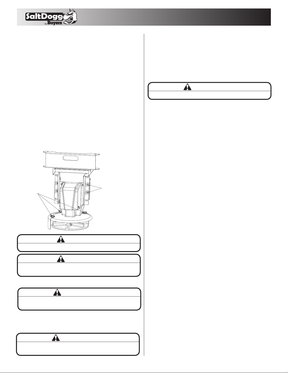
Loosen Screws, Rotate
Shields to Adjust
Spray Pattern
Unscrew Bolts, Slide
Lower Chute Up or Down
Into Desired Position,
Reinstall & Tighten Bolts
Spreader Operation
1. This spreader is equipped with a dual independent speed
controller. To start spreader, press “POWER” switch. Switch
will be illuminated. Auger/ chain and spinner will start rotating.
Auger and spinner can be adjusted independently.
2. To activate vibrator press “VIBRATOR” switch, vibrator switch
will illuminate. Vibrator can operate continuously for 30 min max
with 15 min brakes to avoid overheating.
3. To stop spreader press “ON-OFF” switch again.
4. The controller is equipped with electronic overload and
current spike protection. Controller is not serviceable.
Controller has two LED lights: “ERROR” and “FLASH NUMBER”.
If there is a problem the ERROR LED will illuminate and FLASH
NUMBER LED will give a series of flashes. Count the number of
flashes and refer to the troubleshooting guide provided with the
controller. Additionally you can go online for the troubleshooting
codes at https://snowdogg.com/media/3802/3026671_A.pdf
5. Spreading pattern can be controlled by repositioning of the
baffles on the chute as shown in Fig. 6. Chute heights can be
adjusted to accommodate different vehicle heights (Fig.6).
1. Ensure that the spreader is securely mounted to the vehicle
and that the top screen is installed and secured in the hopper.
2. Remove the tarp, if used.
3. Determine the amount of material that you can safely
transport using your vehicles GVWR/GAWR and the following
table on page 1.
4. Fill the spreader evenly with your material, making sure not to
fill past the top of the hopper.
Fig. 6
WARNING
Never attempt to lift spreader with material in hopper!
WARNING
Never leave material in hopper for extended period of time.
Material can freeze, solidify and seriously damage the spreader
IMPORTANT
Only use dry salt, sand, sand/salt, or cinder/salt mixes in the
spreader. Other materials could cause damage to the machine.
IMPORTANT
When filling the spreader, do not exceed the gross-vehicle-weight
rating (GVWR) or gross-axle-weight rating (GAWR).
IMPORTANT
Overfilling the hopper could damage the spreader & your vehicle.
Spreader Maintenance
1. Wash spreader after every use. Make sure no material is left
under auger/ chain and/or inside trough.
2. Inspect and retighten fasteners after every 5-7 hours of operation.
3. Lubricate bearings every 7-10 hours of operation using
general automotive grease.
4. Inspect terminals/connectors every time you disconnect
spreader from wire harness. Apply thin layer of dielectric grease
on terminals. If any tarnish/corrosion is found, clean terminals
and apply dielectric grease.
5. Use dielectric grease on all electrical connectors before an
electrical connection is made or after connector is disconnected
6. Empty the spreader of all ice control materials when not in
use. Wash out the spreader to prevent material builds up.
7. It is recommended to cover spreader with the tarp during
storage periods.
End of Season Maintenance
1.
Wash spreader. Make sure no material or residue is left in and
outside the hopper.
2.
Lubricate bearing using general automotive grease.
3.
Inspect wire harness, connectors for broken insulation, missing
components. Replace if necessary.
4.
Apply dielectric grease on all electrical connectors.
5.
Store hopper indoors, in a dry, cool place.
6.
Remove controller from truck. Store controller indoors, in a dry
cool place.
7.
Inspect wire near connectors. Check for broken or missing
insulation. Check for tarnished or corroded wires. Trim corroded
wires and replace connectors if necessary
8.
Make sure no material is left on the spinner disc.
9.
Inspect and retighten vibrator fasteners after every 2 hours.
Summer Storage
1.
Apply dielectric grease or similar protective compound on all
electrical connectors & protect them with caps before storage.
2. Disconnect and remove speed controller from vehicle and
store it in dry and cool place. Protect controller from excessive
heat and moisture.
3. Clean hopper and trough from all kinds of debris.
4. Remove, thoroughly lubricate and reinstall trough bearing.
5. Protect hopper from excessive temperatures during
summer storage.
Spreader Materials
The density of materials that can be loaded into the spreader varies
and therefore so will the amount of a given material that can be
carried by the spreader before the maximum load rating is reached.
5
Repair Parts - Chute Assembly Part # 3031475
Bill of Materials
ITEM PART NO. QT Y. DESCRIPTION
1 3030868 1 UPPER CHUTE WELDMENT
2 3030930 1 CHUTE OUTER, POLY
3 3030908 1 MOTOR MOUNT CHUTE
4 3030907 1 MOTOR 12 VDC, .5 HP SPINNER
5 FCS038016075SS 8 SCREW, HHC-3/8-16 X 3/4 SST
6 3012393 1 SPINNER, 14" POLY CW
7 3025065 1 BUSHING STRAIN RELIEF
8 FWF025063007SS 4 WASHER, FLAT 1/4 SAE SS
9 FCS025020075SS 2 SCREW, CAP 1/4-20 X 3/4 SST
10 3008549 2 SCREW,HEXHD CAP 1/4-20X.5 SST
11 3030927 2 SHIELD, CHUTE
12 3031755 3 PLASTIC HEAD THUMB SCREW 3/8-16X3/4 SST
13 3007115 4 WASHER, FLAT 3/8 X 1.5 X.048 SST
14 FWL038069009SS 4 WASHER, LOCK RHS-3/8 SST
15 3007113 1 PIN, CLEVIS, 5/16 X 2-1/2, .141 HOLE ZN
16 3014994 1 PIN,COTTER,1/8IN X 1IN SST
1
2
3
4
5
6
7
8
9
10
11
12
13
14
15
16
Connector Kit Drawing
WIRE HARNESS TO CHUTE
CONNECTOR KIT #3020301
WIRE HARNESS TO
AUGER/CHAIN GEAR MOTOR
CONNECTOR KIT #3024738
WIRE HARNESS TO
CONTROLLER CONNECTOR
KIT #3017233
6
Repair Parts - Auger Hopper Assembly
Bill of Materials
ITEM PART NO. QT Y. DESCRIPTION
1
3044058
1 HOPPER WELDMENT 96 SST
2
3044061
1TROUGH WELDMENT, SST
3
3014960
16 BOLT, 3/8-16 X 1 CARRIAGE SHORT NECK SST
4
3001255
12 NUT, HEX F L NG - 3/8 - 16 SST
5
9240086A
1 BEAR 1 NG, 1 - 1/4 ELANGE 2 HOLE
6
3014756
4 NUT NYLOCK 7/ 16- 1 4 SST
7
3033660
1 AUGER PR02500 5.25 VARIABLE LH
8
3007068
1 CAP SCREW, HX HD-3/8-16X3 SST
9
FNE038016044SS
15 NUT, NYLOCK 3/8-16X7/16 SST
10
3033663
1SLEEVE, AUGER ADAPTER
11
3024575
1 GEAR MOTOR CONVEYOR 12 VDC
12
1410200
1 BEARING, ELANGED 1-1/8"
13
3033003
1 SPACER, GEAR MOTOR
14
FWF038100007SS
4 WASHER, ELAT 3/8 USS SST
15
FWL038069009SS
4 WASHER, LOCK RHS-3/8 SST
16
FCS03801610 OSS
8 SCREW, HHC 3/8- 16 X 1 304 SST
17
3007416
1 VIBRATOR 200 LBS 12 VDC
18
3044067
11NVERTED VEE,WELDMENT
ITEM PART NO. QT Y. DESCRIPTION
19
3044068
1MOTOR COVER, WELDMENT
20
3033076
1CHUTE ATTACHMENT
21
3012144
4 BOLT, CARRIAGE, 5/16-18 X 1 SST
22
FNE031018034SS
4 NUT, NYLOCK 5/16-18 SS
23
3011132
3 DECAL, SALT DOGG, BLK/WHT ON CLR 18X6.314
24
3017121
2 BRACKET, RECEPTACLE SZ8 DEUTSCH
25
FCS038016075SS
2 SCREW, HHC-3/8- 16 X 3/4 SST
26
3017982
2 WIRE BUSHING OPEN/CLOSED HEYCO 2867
27
FWE025063007SS
4 WASHER, ELAT 1/4 SAE SS
28
FCS025020075SS
4 SCREW, CAP 1/4-20 X 3/4 SST
29
3044229
1 LABEL SERIAL NUMBER 1 470 6 0ISSE
30
1499035
1LABEL, WARNING 3
31
1499020
1LABEL, WARNING 1
32
1499045
1LABEL, WARNING 4
33
3036278
1 GROMMET, 1.50 DI AMETER
34
3032591
1 DECAL, DANGER, MOVING CONVEYOR/ AUGER
35
3032593
1 DECAL, DANGER, CONVEYOR
36
3032595
1 DECAL, CAUTION, MOUNTING
27
28
3
4
18
6
5
32
23
17
131 29 30 33 7 25 9 8 12 10 16 15 13 11
24
26
22
21
20
14
19
2
7
Repair Parts
Bill of Materials
ITEM PART NO. QT Y. DESCRIPTION
1 3044059 1 HOPPER ASM 2 CU YD SST
2 3031475 1 CHUTE SWING ADJ
3 3044071 1 HARDWARE KIT 147 0 6 0ISSE
4 3016934 1 CONTROLLER SPEED 12 VDC, 60 AMP
5 3030628 1 WIRE HARNESS MAIN
6 3035938 1 KIT POWER CABLE REPLACES 3016943
7 203700 1 WIRE ASSEMBLY, 36 LONG
8 1496505 1 HOLD DOWN KIT, SPREADER (4 STRAPS)
9 3033174 2 PIN, CHUTE ATTACHMENT
10 HP9 2 PIN, HAIR COTTER, .09 ZINC
11 3008186 1 SCREEN, TOP, POLY HOPPER
1
10
11
3
9
7
5
4
6
82
8
9049 Tyler Blvd. • Mentor, Ohio 44060
Phone (440) 974-8888 • Fax (800) 841-8003
www.buyersproducts.com
3044178_A
SPREADER WARRANTY INFORMATION
This warranty replaces all previous warranties and no employee of this company is authorized to extend additional warranties, or agreements, or
implications not explicitly covered herein.
Buyers Products Company warrants all parts of the product to be free from defects in material and workmanship for a period of two (2) years. Parts
must be properly installed and used under normal conditions. Normal wear is excluded.
Any part, which has been altered, including modifications, misuse, accident, or lack of maintenance will not be considered under this warranty.
The sole responsibility of Buyers Products Company under this warranty is limited to repairing or replacing any part(s), which are returned, prepaid,
30 days after such defect is discovered, and returned part(s) are found to be defective by Buyers Products Company.
Authorization from Buyers Products Company must be obtained before returning any part. The following information must accompany defective
parts returned to Buyers Products Company: RMA #, spreader model, serial number, date installed, and distributor from whom purchased.
Buyers Products Company shall not be liable for damage arising out of failure of any unit to operate properly, or failure, or delay in work, or for any
consequential damages. No charges for transportation or labor performed on any part will be allowed under this warranty.

Other Buyers Spreader manuals

Buyers Salt Dogg SHPE2000 User manual

Buyers

Buyers Salt Dogg SHPE2000 User manual

Buyers SaltDogg 1490757SSE User manual

Buyers

Buyers SaltDogg 1490757SSE User manual

Buyers Salt Dogg SHPE1000 Series User manual

Buyers

Buyers Salt Dogg SHPE1000 Series User manual

Buyers ATVS15A User manual

Buyers

Buyers ATVS15A User manual

Buyers SaltDogg 14708F463211 User manual

Buyers

Buyers SaltDogg 14708F463211 User manual

Buyers SaltDogg PRO4000 User manual

Buyers

Buyers SaltDogg PRO4000 User manual

Buyers SaltDogg SHPE2500 Series User manual

Buyers

Buyers SaltDogg SHPE2500 Series User manual

Buyers Salt Dogg SHPE1500 User manual

Buyers

Buyers Salt Dogg SHPE1500 User manual

Buyers SaltDogg SHPE6000CH User manual

Buyers

Buyers SaltDogg SHPE6000CH User manual

Buyers SaltDogg SHPE2000 User manual

Buyers

Buyers SaltDogg SHPE2000 User manual

Buyers UTVS16 User manual

Buyers

Buyers UTVS16 User manual

Buyers ATVS100 User manual

Buyers

Buyers ATVS100 User manual

Buyers ATVS15 User manual

Buyers

Buyers ATVS15 User manual

Buyers TB150BG User manual

Buyers

Buyers TB150BG User manual

Buyers ATVS100 User manual

Buyers

Buyers ATVS100 User manual

Buyers TGS05B User manual

Buyers

Buyers TGS05B User manual

Buyers SaltDogg SHPE3000 User manual

Buyers

Buyers SaltDogg SHPE3000 User manual

Popular Spreader manuals by other brands

Sulky Burel DX20 Original instructions

Sulky Burel

Sulky Burel DX20 Original instructions

Husky ELITE operating instructions

Husky

Husky ELITE operating instructions

Equalizer International SG13TE Operator's instruction manual

Equalizer International

Equalizer International SG13TE Operator's instruction manual

Boss Snowplow SNR24030 owner's manual

Boss Snowplow

Boss Snowplow SNR24030 owner's manual

The Handy THTS instruction manual

The Handy

The Handy THTS instruction manual

Chapin TOW BEHIND manual

Chapin

Chapin TOW BEHIND manual

Teagle Telehawk quick start guide

Teagle

Teagle Telehawk quick start guide

SnowEx V-Maxx G2 owner's manual

SnowEx

SnowEx V-Maxx G2 owner's manual

Marshall Amplification MS45 Operating/safety instructions

Marshall Amplification

Marshall Amplification MS45 Operating/safety instructions

Lesco Commercial plus 705698 Parts list and instructions

Lesco

Lesco Commercial plus 705698 Parts list and instructions

Farmhand 70LB Assembly and operating instruction

Farmhand

Farmhand 70LB Assembly and operating instruction

P.Lindberg SP31506 Original manual

P.Lindberg

P.Lindberg SP31506 Original manual

Meyer SEL SERIES Installation and operating instruction manual

Meyer

Meyer SEL SERIES Installation and operating instruction manual

Cub Cadet 80 LB Parts list and instructions

Cub Cadet

Cub Cadet 80 LB Parts list and instructions

Harbor Freight Tools 90155 Assembly & operating instructions

Harbor Freight Tools

Harbor Freight Tools 90155 Assembly & operating instructions

Millcreek 100P Operator's manual

Millcreek

Millcreek 100P Operator's manual

Modulift MOD 70 User instructions

Modulift

Modulift MOD 70 User instructions

Land Pride PS25120 Specifications

Land Pride

Land Pride PS25120 Specifications

manuals.online logo
manuals.online logoBrands
  • About & Mission
  • Contact us
  • Privacy Policy
  • Terms and Conditions

Copyright 2025 Manuals.Online. All Rights Reserved.