Bio Smart Technologies BioSmart 500F User manual

Therapeutic Infrared Heat
.
.
B IOS MART
®
Save these
Instructions
Includes:
Application Guidelines
User Information & Guidelines
Operating Instructions
Warranty & Servicing
In-Wall Heater
Owner’s Manual
Therapeutic infrared heating systems
for a green, healthy environment
with Patented BioSmart®
Air Filtration Technology
BioSmart®In-Wall Far Infrared Heaters. Feel the Difference.
BioSmart Technologies

Customer/Warranty Service: 800-595-9605
BioSmart® BIO-1000F
In-Wall Edition Far Infrared Heater

Page 1
©2013 BioSmart Technologies
Table of Contents
Congratulations on Your Purchase! 2
Why Use a BioSmart®Heater 4
Far Infrared Technology Benefits 6
Unpacking Your New BioSmart®Heater 7
Heater Care 7
USE RESTRICTIONS 7
BioSmart®500F Features & Functions 8
BioSmart®1000F Features & Functions 9
How many units do I need? 10
Installation Instructions 10
Wiring Diagrams 13
BIO-1000F/120v Wiring Schematic 13
BIO-500F/120v Wiring Schematic 13
For Your Safety/Warning 14
For Best Performance 14
Operating Instructions 14
Maintenance 14
Troubleshooting Your BioSmart®Heater 15
BioSmart®1000F In-Wall Heater Specifications 16
BioSmart®500F In-Wall Heater Specifications 17
Diagram of BioSmart®1000F In-Wall Heater 18
Diagram of BioSmart®500F In-Wall Heater 19
Warranty & Service Information 20

Page 2
Customer/Warranty Service: 800-595-9605
Congratulations on Your Purchase!
Congratulations on purchasing your
BioSmart®Therapeutic Ceramic Far Infrared
Heater!
One of the best things about using your new
BioSmart®Therapeutic Ceramic Far Infrared
Heater is the money you will save on gas and
electric bills.
Utility eld tests show that the BioSmart®Ceramic Far Infrared Heater
uses an average of 35% less energy than conventional electric furnace/
baseboard systems. And with current fuel prices, the BioSmart®heater
will save you even more money than if you were using heating oil or gas
heat.
That means drastic reductions in your heating bills -- up to 50%, depending
on the type of heating system you have currently installed.
The BioSmart® is a giant of unparalleled eciency. The far infrared heating
technology utilized in the heater warms the objects in the room, as well
as the walls and oor. It evenly heats everything in the room, from top to
bottom. The heat in the room will never hover uselessly near the ceiling
again!
In addition to helping you keep money in your pocket, the BioSmart®goes
a step beyond to also enhance your health and the quality of comfort you
experience in the heated room. The far infrared Ceramic heating system
will not burn, dry out, or pollute the air with impurities. This protects the
natural humidity level and produces a soft, ion-balanced heat. Using this

Page 3
©2013 BioSmart Technologies
soft far infrared heat is a better, more comfortable and more healthy
way to heat a room.
There are many therapeutic benets that can be attributed to far
infrared heat. Its use as an integral part of many medical therapies is well
documented. Now you can enjoy the benets of therapeutic far infrared
heat with the BioSmart®Ceramic Far Infrared Heater.
Please read the operating instructions carefully for safe and optimum
enjoyment of your new BioSmart®Therapeutic Ceramic Far Infrared
Heater.
Thank you for your purchase!
BioSmart® Infrared Heaters.
Live in Comfort.
BioSmart Technologies

Page 4
Customer/Warranty Service: 800-595-9605
Why Use a BioSmart®Heater
BioSmart® heating systems are the ultimate in green technology engineering -- easy
to install, exceptionally economical and extremely quiet, they produce comfortable,
healthy, therapeutic far infrared heat. BioSmart® heaters also purify the air that is
processed through them, making them a sanitary source of heat.
Far infrared heat is a highly efcient and therapeutic heat source. By virtue of its
shorter wavelength, far infrared is able to penetrate the body and solid objects
faster than conventional radiant heat. BioSmart® heating systems use this property
of far infrared to evenly and comfortably heat a room. Far infrared heat is the most
comfortable source of heat and has been used for years as a therapeutic treatment for
various conditions including muscle and joint pain, stiffness, and cardiovascular and
general circulation problems.
Producing far infrared heat requires localized generation of infrared wave in order to
optimize the efciency and money/energy savings produced when using a far infrared
heating source. This design advantage eliminates the need for a ductwork system to
distribute the heat through various rooms of a home or ofce. Eliminating ductwork
also eliminates the bacteria, dust, pollen and mold that accumulates in a conventional
air conditioning and heating duct system. These pollutants can cause irritation and
a potential health problem, especially for those with respiratory sensitivities and
allergies, including asthma.
Energy Saving Benets
It requires less energy to heat the room with far infrared heat than with other
conventional heating sources. Additionally, room temperatures of 68 degrees (F) with
far infrared heat feel like 72 degrees (F), so you can set the thermostat back 4-5 degrees
and experience the same comfort levels utilizing less energy. The temperature on the
oor and at the ceiling remains the same without any supplemental fan circulation
to keep the temperature balanced throughout the room, even in rooms with high
ceilings.
With a BioSmart® heating system you can heat only those spaces which are in use
and require the heat. Zoned heating is as much as 50% more economical to use when
the entire home or ofce does not require heat in all areas 100% of the time. The
cost savings from this feature alone makes initial installation of the BioSmart® heating
system pay for itself in a matter of months. If you really want to save on energy costs,
heating with BioSmart® far infrared heat is going to be spectacular.
Quiet Operation
BioSmart® fan systems are virtually silent, distributing heat at over 150 cubic feet per
minute per heating unit. They are quieter than forced air systems and do not have
the typical cracking and popping sounds heard with baseboard heaters. When rated
against other conventional wall heating systems, there is no comparison to the quiet
operation of the BioSmart® fan system. BioSmart® fans operate at 18 dB compared to
the typical 65 dB for other wall heating systems.

Page 5
©2013 BioSmart Technologies
Better Heat Distribution
The nature of far infrared waves allows the heater to be installed higher on the wall
than conventional wall heater systems without compromising the transfer of the heat
to the oor. The advantage of the higher installation on the wall guarantees that
furniture and other obstructions to the airow from the heater are eliminated. Child
tampering is also eliminated.
Even distribution of infrared wave is also assured since the air space above the
furniture is virtually unrestricted. When conventional heat sources are vented through
the ceiling to save on construction costs, the heat remains near the ceiling and must
be pushed down with ceiling fans. This is not required with infrared heat.
Accurate Temperature
BioSmart® heating systems utilize state of the art electronics and internal electronic
thermostats for pin-point, one-degree accuracy. That means more accurate control of
comfort level settings and a warm, comfortable environment for you and your family.
Cost-Effective
Components in the BioSmart® heating system are designed to last longer than other
wall heaters. BioSmart® warranty coverage and service procedures are simple to follow
and the heaters can be serviced in ten minutes or less should repair be required. The
cost to purchase and install a BioSmart® infrared heating system for your entire home
is usually much cheaper than the cost of installing a central forced air heating system.
Patented Proprietary Technology
BioSmart® heaters contain a proprietary, high-efciency far infrared heat exchanger
which produces more far infrared heat her kilowatt than conventional ceramic,
quartz, or carbon plates. Patent pending coverage of more than 30 distinct features in
the BioSmart® heater are what makes the BioSmart® technology a truly unique energy
efcient heat source for your home or ofce.
Quality Assurance
BioSmart® heating systems come with C-TUV-US certications representing equivalent
approvals both in UL and CSA classications. BioSmart® heaters are manufactured
in Taiwan and China through AcePower Electronics, which includes a consortium
of engineers, vendors and manufacturers. AcePower Electronics is also a certied
ISO 9000 manufacturer and the exclusive manufacturer for BioSmart Technologies
heaters and air puriers.

Page 6
Customer/Warranty Service: 800-595-9605
Far Infrared Technology Benefits
40
45
50
55
60
65
70
75
80
85
Temperature (Fahrenheit)
0 1 2 3 4 5
Time (Hours)
Coil-Type Radiant HeaterBioSmart Far Infrared Heater
Dierence in time required to reach given temperature
47
48
47
67
70 73
76
80
74
83
75
BioSmart Far Infrared vs Standard Coil-Type Radiant Heater
Nearly 20%
faster to 72 °F
e BioSmart heater reached 75 °F 70%
faster, that’s more than 2 hours sooner!
Test booth starting
temperature
20 - 50% Energy savings
with BioSmart Infrared
Faster warm-up and retention time means dramatic
energy savings with BioSmart Infrared
Page 7
©2013 BioSmart Technologies
READ ALL INSTRUCTIONS BEFORE USING THE HEATER
• DO NOT alter the heater’s design, or you will void the warranty.
• DO NOT block the front of the heater.
• DO NOT place anything directly in front of the heater.
• DO NOT cover the unit as this may block airow and cause the heater to
malfunction.
• DO NOT insert or allow foreign objects to enter any ventilation or exhaust
opening as this may cause an electric shock or damage the heater.
• Heater has hot parts inside. DO NOT use it in areas where gasoline, paint, or
ammable liquids are used or stored.
• Do not block air intakes or exhaust in any manner.
• Use this heater only as described in this manual. Any other use not recommended
by the manufacturer may cause re, electrical shock, or injury to persons.
SAVE THESE INSTRUCTIONS
Unpacking Your New BioSmart®Heater
1. INSPECT the package for any obvious damage.
2. UNPACK the heater: cut open taped box edges, fold back box aps. Gently turn
entire box upside down; lift box from protective packaging.
3. REMOVE the protective packaging materials from the inside of the heater’s heat
exchanger, making sure that all combustible materials have been removed from
around the black ceramic heating elements.
4. INSPECT the unit to make sure that there are no cracks in the black ceramic
heating elements.
5. PROCEED with the “Installation Instructions” on page 10.
Heater Care
General Maintenance and Care
Routinely inspect the air registers on the unit to make sure that no dust has accumulated.
Vacuum as you would any conventional air duct.
It is suggested that an annual dusting of the ceramic plates be performed in order to
eliminate any residual accumulation of dust during the summer months. In order to
accomplish this, the front plastic panel must be removed by removing the four screws
and lifting up to release the panel from the top clip.
!
WARNING
ANY REQUIRED SERVICE SHOULD ONLY BE PERFORMED BY
AN AUTHORIZED SERVICE REPRESENTATIVE
CAUTION: RISK OF ELECTRICAL SHOCK
DISCONNECT POWER BEFORE SERVICING
USE RESTRICTIONS

Page 8
Customer/Warranty Service: 800-595-9605
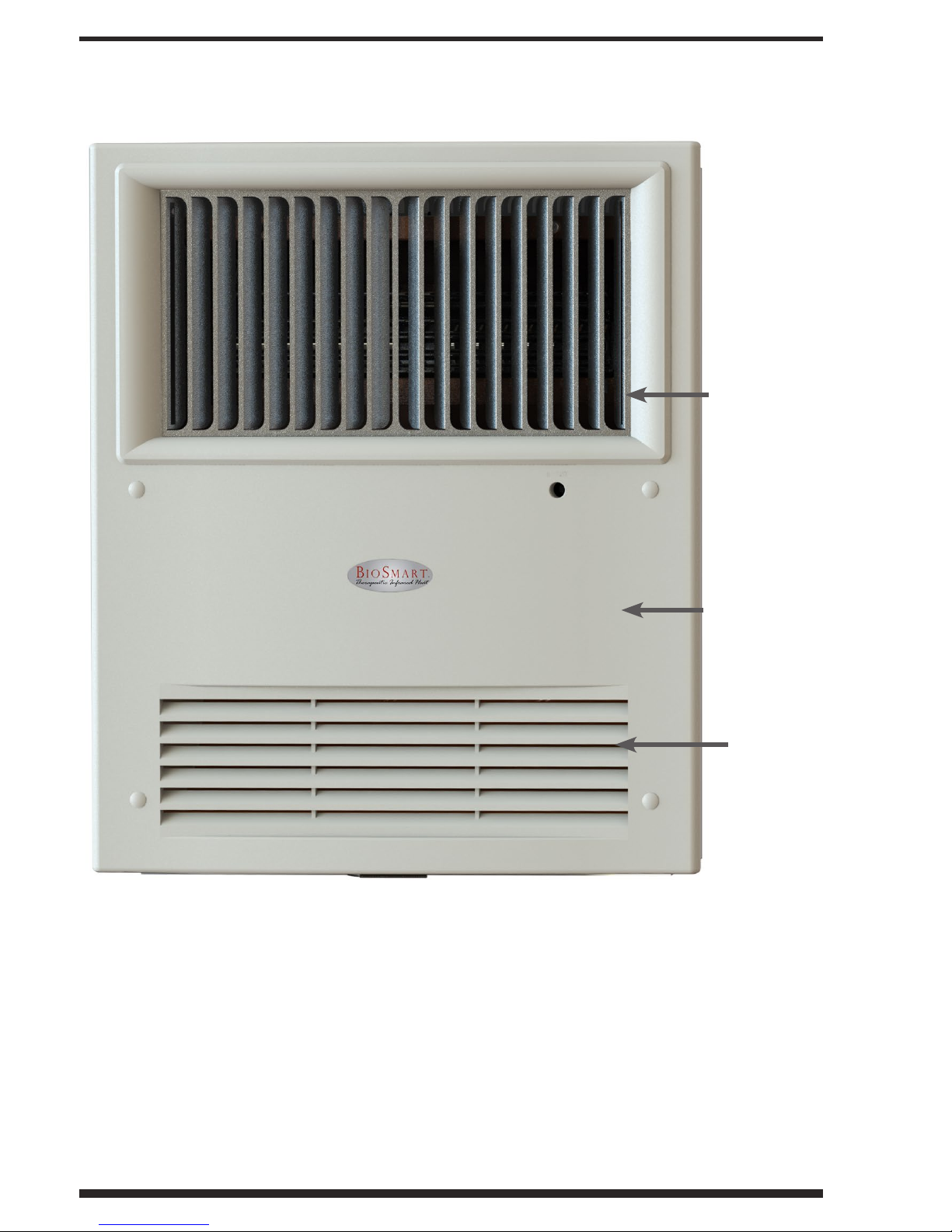
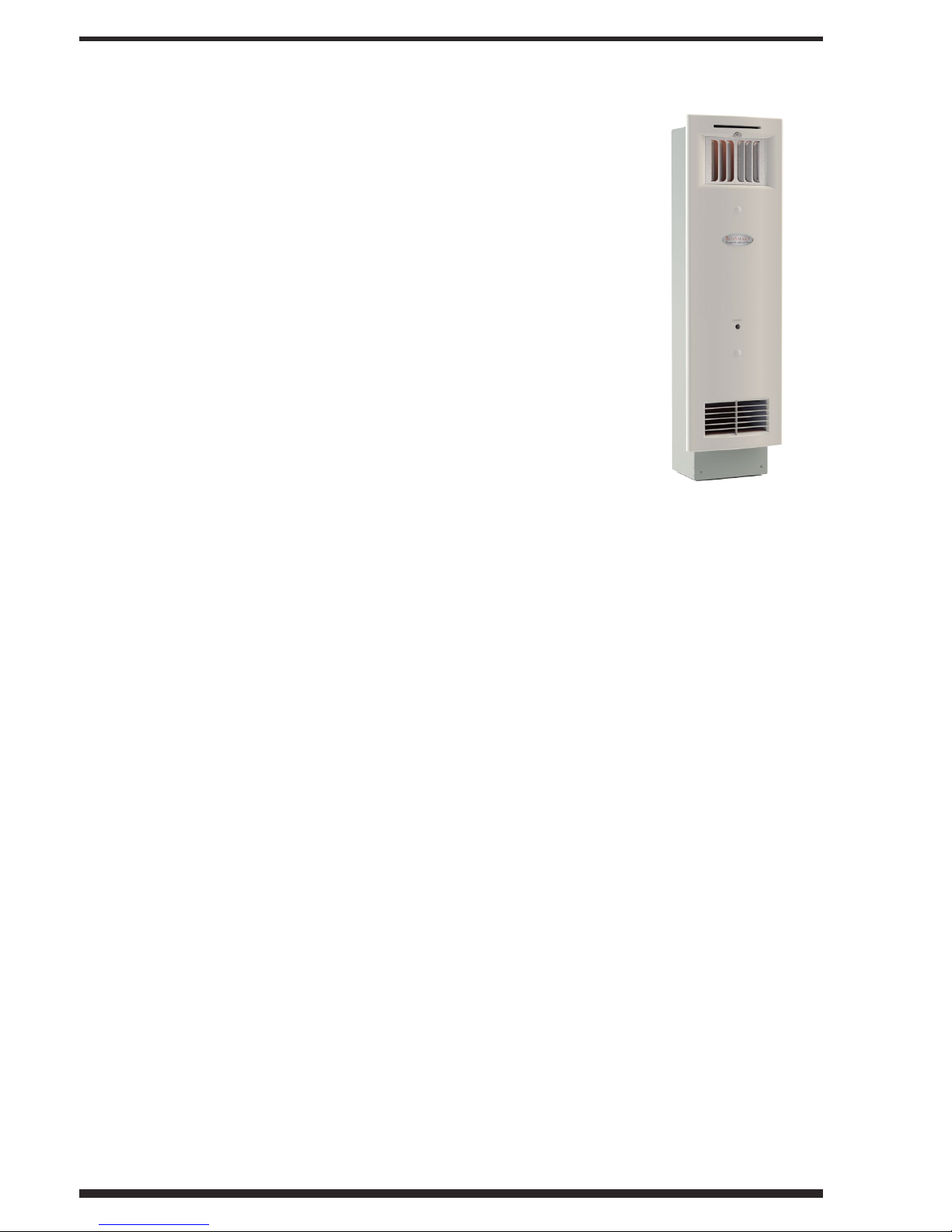
BioSmart®500F Features & Functions
Heat Register
Cabinet cover
Intake
Page 9
©2013 BioSmart Technologies
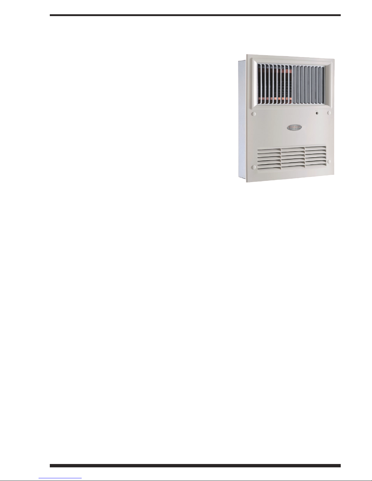
BioSmart®1000F Features & Functions
Heat Register
Intake
Cabinet cover

Page 10
Customer/Warranty Service: 800-595-9605
How many units do I need?
When determining the number of units you will need, take into consideration:
• The insulation factor, and window size & placement
• The mean outside temperature during the coldest days of the year
• The size of each room
• The overall size of the home
• The number of oors involved
• The entrance and egress points
In lieu of overall engineering calculations and thermal loss calculations, a general rule
of thumb can be applied to determine the number of units you will need if using the
in-wall unit as a primary heating source:
New construction (coldest day above 5 degrees), standard insulation, one
window per room:
Room size up to 500 sq. feet: 1 unit
Room size above 500 to 1000 sq. feet: 2 units
New construction (coldest day below 5 degrees) & all remodels, standard
insulation:
Room size up to 350 sq. feet: 1 unit
Room size above 350 to 700 sq. feet: 2 units
Hallways and Nooks: 1 unit per 400 sq. feet
Closets and Bathrooms: 1 unit per 400 sq. feet
Installation Instructions
Easy Installation
The BIO-500F/1000F were designed for installation in a standard 2”x4” wall with
either 1/2” or 5/8” sheetrock. The units comes with brackets for both new installations
and retrots.
The heaters can be mounted from 12” above the oor up to 12” down from the
ceiling.

Page 11
©2013 BioSmart Technologies
12” 12”
Installation Range
Backets for BIO-1000F
new installation
Backets for BIO-500F
retrot installation

Page 12
Customer/Warranty Service: 800-595-9605
Heater Wiring
Regardless of the model chosen, there are 5 wires inside the base of the heater which must be
wired correctly. Three wire contacts are required to obtain the power source. The wiring code
is the same for 120 volt units.
The heater must be provided with a disconnect device (switch/breaker) from the supply mains
having a contact separation in all poles that provide full disconnection with a contact separation
of at least 3 mm.
On the large in-wall unit the black is hot, the red is neutral, and the green is ground. On the
small in-wall unit the black is hot, the blue is neutral and the green is ground. On both units
the yellow and white wires go directly to the thermostat.
No external power supply is needed. Any attempt to attach an external power supply will cause
damage to the internal components and will result in product failure.
When connecting multiple units to a single thermostat, the units must be connected in parallel
with all yellow and all white wire leads connected to their same respective terminals on the
thermostat.
Failure to follow these guidelines will result in internal transformer failure and product failure.
Typical wiring procedure using conventional 12/2 wire on a large heater.
Thermostat Wiring
The heater is equipped with micro-voltage thermostat leads. Any low-voltage micro or milliamp
thermostat will operate the two thermostat wires. No voltage is required to the leads and no
external power supply is needed.
The thermostat should be located at least 5 feet from the heater.
Page 13
©2013 BioSmart Technologies
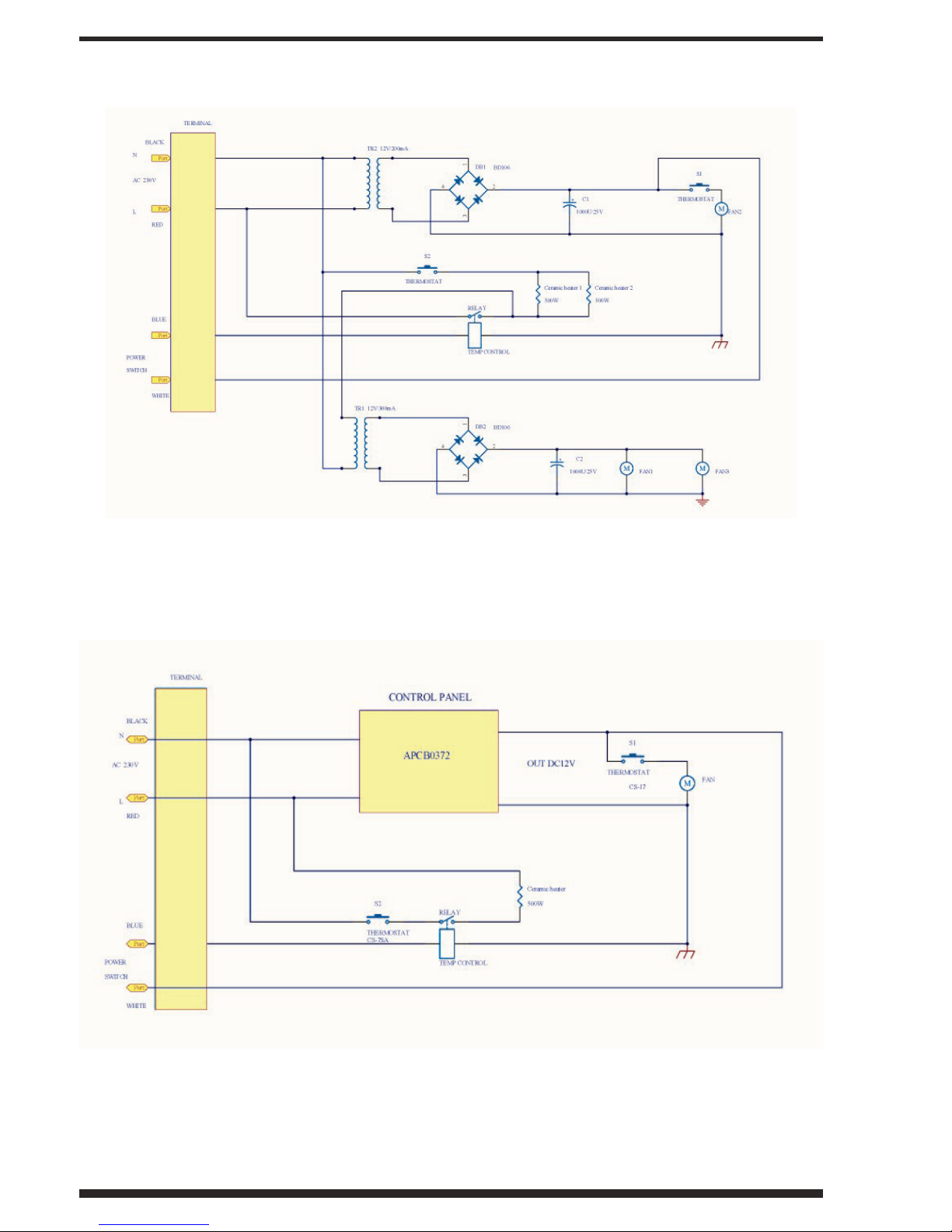
Wiring Diagrams
BIO-1000F/120v Wiring Schematic
* Switch must have a contact separation in all poles that provide full disconnection with a
contact separation of at least 3 mm and rated 10A minimum.
BIO-500F/120v Wiring Schematic
*

Page 14
Customer/Warranty Service: 800-595-9605
For Your Safety/Warning
Do not place objects in front of infrared wall units that have been mounted lower than those
parameters suggested in the installation instructions. Doing so will cause the unit to overheat,
which will trigger the high temperature limit switch, resulting in a potential service call to reset/
replace the switch.
For Best Performance
It is recommended that the air ow pattern in the room becomes circular. This is accomplished
by mounting the heater to one side of the room, as per the illustration, in order to create a
circular ow around the room.
Where multiple units are installed in larger rooms, this circular pattern can be maintained by
positioning the units to complement the air ows. This is accomplished by positioning them in
opposite corners of the room.
Operating Instructions
The units are self-regulating. Temperature is controlled via a thermostat located preferably on
the opposite wall from the heating unit. The heater fans will turn on when the power to the
infrared heating elements turn on. After the heating elements have come up to full temperature,
a third fan will turn on to increase the airow into the room. This third fan will remain running
even after the heating elements have been shut down by the thermostat, in order to distribute
the remaining heat in the heating elements into the room.
Temperatures can be regulated from a central control (sold separately) or the heating units can
also be independently turned on or off from a remote location via a central on/off switch for
each unit. The switch is connected between the low-voltage thermostat control and one of the
lead wires to the thermostat from the thermostat contact on the heater.
Maintenance
Routinely inspect the air registers on the infrared unit to make sure that there is no dust
accumulation. Vacuum as you would any conventional heat or air conditioning duct.
It is suggested that an annual dusting of the ceramic plates be performed in order to eliminate
any residual accumulation of dust during the summer months. Other than this, there are no
maintenance requirements involved. In order to accomplish this, the front plastic panel must
be removed by removing the four screws and lifting up to release the panel from the top clip.

Page 15
©2013 BioSmart Technologies
Troubleshooting Your BioSmart®Heater
Problem Solution
Heater’s airow is
reduced.
Check for any objects that could obstruct airow.
If the heater’s airow is still diminished or has
stopped, please call Customer Service.
Heater fan still on
20 minutes after
shut-down.
This is most likely a defective fan relay. Please call
Customer Service.
Heater will not
turn on.
First, push the reset button. Next, check the
thermostat leads. Short the leads out and if the
heater turns on you have a defective thermostat,
otherwise you have a defective relay in the heater.
Call a service technician for installation of a new
relay.
Heater doesn’t
seem to be getting
hot enough.
Most likely, one of the ceramic elements is burnt
out or the connection to the element is bad. Call
Customer Service for help, the defective ceramic
plate may need replacing.
Heater does not
heat-up
First, push the reset button. Next, check the
thermostat leads & listen to determine if the rst
fan is operating. If so, call a service technician for
installation of a new heat relay.
The heater is
noisy.
Check for obstructions to the fan blades. If there
are none, you have a defective fan. Please call
Customer Service.
Page 16
Customer/Warranty Service: 800-595-9605
BioSmart®1000F In-Wall
Heater Specifications
Model BIO-1000F
• Cabinet: All metal - 22 & 24 gauge with synthetic,
paintable shell
• Weight: 13 lbs
• Dimensions: 16” x 12 5/8” x 4” (HxWxD)
• Power Requirements: 120 or 220 volt AC
• Power Consumption: 12.5A @ 120 volt, 6.75A
@ 220 volt, 1500 watt
• Chassis Safety Insulation: Exceeds all
government and independent laboratory
standards for safety in an installed heating
appliance (a safety standard that exceeds other
manufacturer’s specications).
• Internal Ceramic Blanket: Provides R45 insulation between the wall and the
heater. The heater cabinet remains cool to the touch while delivering warm
(105° C) far infrared heat into the room.
• Thermostat Type: Any standard digital, programmable or mechanical (no in line
high voltage)
• Safety Cut-Off: Prevents damage to the unit
• Life Expectancy: 25+ Years
• Zoned Heat Capability: Pre-wired - simple two-wire contact to any zone control
panel
• Heat Type: therapeutic far infrared heat
• Heat Chamber: Copper-lined for maximum ion transfer
• Heating Elements: 2 -500 watt ceramic far infrared emitters
• Infrared Emitter Life Expectancy: 40,000 hours
• Heat Output: 4,800 BTU infrared heat
• Fan System: 3 high volume, low noise 90mm DC Fans
• Fan Noise Level: 18 dB - practically silent
• Listed Approvals: C-TUV-US (International UL Equivalent)
• Warranty: 5-Year limited
BIO-1000F
Page 17
©2013 BioSmart Technologies
BioSmart®500F In-Wall Heater
Specifications
Model BIO-1000F
• Cabinet: All metal - 22 & 24 gauge with synthetic,
paintable shell
• Weight: 8 lbs
• Dimensions: 20 1/2” x 4 3/4” x 4” (HxWxD)
• Power Requirements: 120 or 220 volt AC
• Power Consumption: 6.3A @ 120 volt, 3.4A @ 220 volt,
1500 watt
• Chassis Safety Insulation: Exceeds all government and
independent laboratory standards for safety in an installed
heating appliance (a safety standard that exceeds other
manufacturer’s specications).
• Internal Ceramic Blanket: Provides R45 insulation
between the wall and the heater. The heater cabinet remains cool to the touch
while delivering warm (105° C) far infrared heat into the room.
• Thermostat Type: Any standard digital, programmable or mechanical (no in line
high voltage)
• Safety Cut-Off: Prevents damage to the unit
• Life Expectancy: 25+ Years
• Zoned Heat Capability: Pre-wired - simple two-wire contact to any zone control
panel
• Heat Type: therapeutic far infrared heat
• Heat Chamber: Copper-lined for maximum ion transfer
• Heating Elements: 1 -500 watt ceramic far infrared emitters
• Infrared Emitter Life Expectancy: 40,000 hours
• Heat Output: 2,800 BTU infrared heat
• Fan System: 1 high volume, low noise 90mm DC Fan
• Fan Noise Level: 38 dB
• Listed Approvals: C-TUV-US (International UL Equivalent)
• Warranty: 5-Year limited
BIO-500F
Page 18
Customer/Warranty Service: 800-595-9605
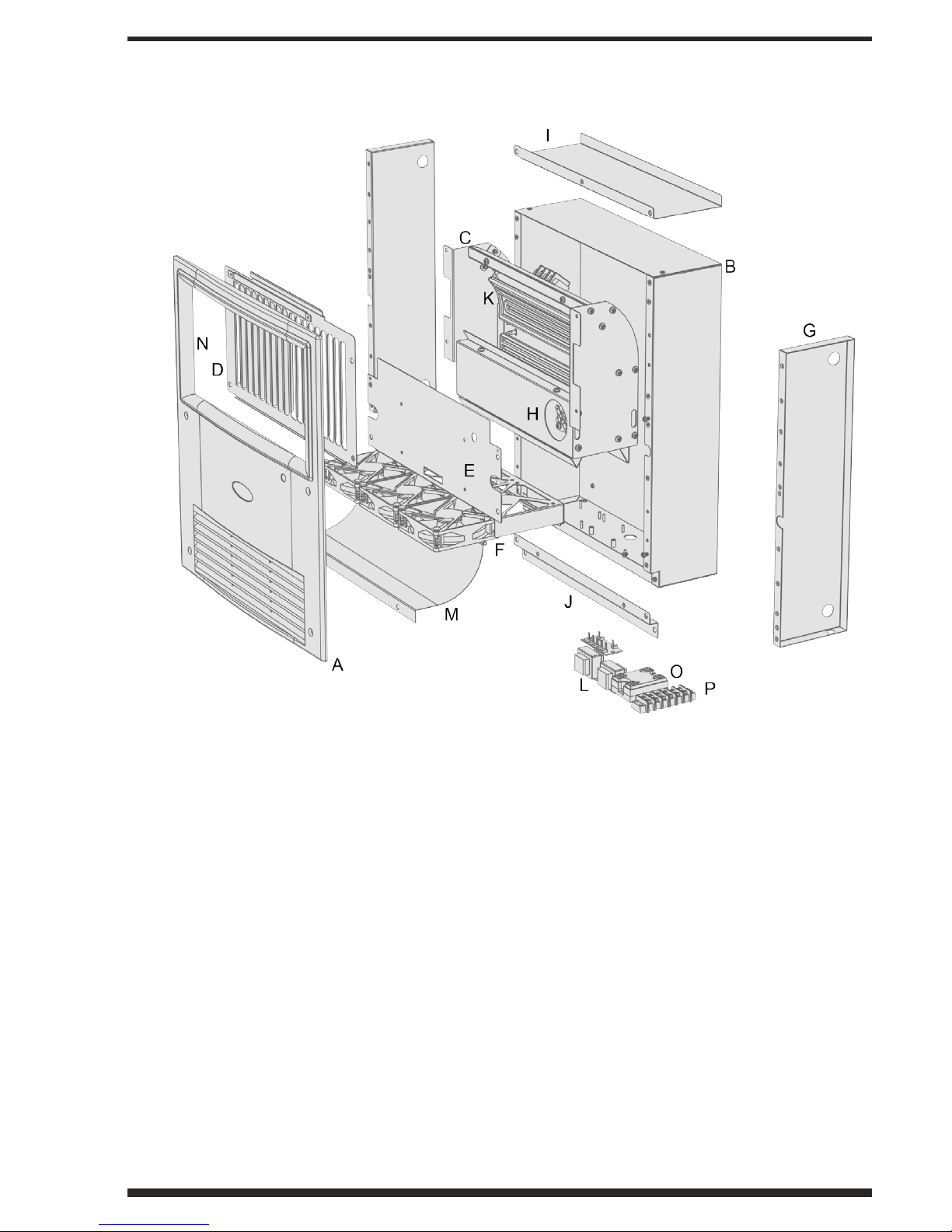
Diagram of BioSmart®1000F In-Wall Heater
A. Cover
B. Case
C. Heater Core
D. Grill
E. Fan Holder
F. Fans
G. Insulator Cover
H. High Limit Reset
I. Top Case Bracket
J. Bottom Case Bracket
K. Ceramic Heating Element
L. PCBoard
M. Bafe
N. Heat Resistant Insert
O. Solid state relay
P. Connection Plate
This manual suits for next models
2
Table of contents
Other Bio Smart Technologies Heater manuals


Popular Heater manuals by other brands

Generac Power Systems
Generac Power Systems MAC 550F owner's manual

Frost Fighter
Frost Fighter IDF350-II Installation, operation and maintanance manual

Ironside
Ironside 200701 quick guide

Sealey
Sealey IRC153110V instructions

Comfier
Comfier CF-6003 user manual

Qmark
Qmark MUH Series Installation & maintenance instructions


