BIO UV BIOSUN 340 Manual
BIOSUN-340_(Anglais) - DOC012466 - Ind. B03 - 21/06/2017
BIOSUN
340W
INSTALLATION AND MAINTENANCE MANUAL

BIOSUN-340_(Anglais) - DOC012466 - Ind. B03 - 21/06/2017 Copyright BIO-UV
Marque, Modèles et Brevets déposés - Produits exclusifs
Page 2
We thank you for choosing BIOSUN.
Our equipment has been designed to give you reliable and safe operation for many years to come.
The BIOSUN terminals have been designed for speed and ease of installation.
Their design also makes them easy to maintain.
Read these instructions carefully in order to optimize the operation of your device.
TABLE OF CONTENTS:
Pages
A. Technical characteristics.................................................................................................................................................3
B. SafetyWarnings...............................................................................................................................................................4
C. BIOSUNterminal description..........................................................................................................................................5
1. Overview.........................................................................................................................................................................................................................5
2. Hydraulic diagram.......................................................................................................................................................................................................6
D. Installation guide ............................................................................................................................................................7
1. Foreword ........................................................................................................................................................................................................................7
2. Detail of provided elements....................................................................................................................................................................................7
3. Mounting of photovoltaic panels .........................................................................................................................................................................8
a.) Preparation .............................................................................................................................................................................................................8
b.) Assembly..............................................................................................................................................................................................................10
4. Wiring of photovoltaic panels.............................................................................................................................................................................22
5. Instruction to mount the BIOSUN 340 terminal ...........................................................................................................................................23
E. Instructions for the first commossioning of the BIOSUN 340 terminal ..................................................................... 25
F. Instructions to use the BIOSUN 340 terminal.............................................................................................................. 26
1. Production...................................................................................................................................................................................................................26
2. Start-up the terminal...............................................................................................................................................................................................26
G. Instructions for servicing of the BIOSUN 340 terminal.............................................................................................. 27
1. Backwashing the filter ............................................................................................................................................................................................27
2. Tank draining .............................................................................................................................................................................................................27
3. Solar panel cleanliness...........................................................................................................................................................................................28
4. Preventive disinfection ..........................................................................................................................................................................................28
5. Functional check of the photovoltaic power supply..................................................................................................................................28
H. Procedure for lap, quartz sleeve or seals replacement.............................................................................................. 29
I. Replacement of the filter cartridges (option)............................................................................................................... 32
J. Maintenance file............................................................................................................................................................ 33
K. Electrical description.................................................................................................................................................... 34
L. Blown up view ............................................................................................................................................................... 35
M. Errors and remedial action: regulator ........................................................................................................................ 36
N. Frequently asked questions ........................................................................................................................................ 38
O. Warranty terms............................................................................................................................................................. 39
ANNEX 1: Clearance dimensions, Blown up view, Designation .................................................................................... 41
ANNEX 2: Electrical diagrams.......................................................................................................................................... 43
BIOSUN-340_(Anglais) - DOC012466 - Ind. B03 - 21/06/2017 Copyright BIO-UV
Marque, Modèles et Brevets déposés - Produits exclusifs
Page 3
A. TECHNICAL CHARACTERISTICS
BIOSUN RANGE UNIT BIOSUN 340
FUNCTIONAL CHARACTERISTICS
Flowrate l/h 500
Number of hours of production per day h 4
Volume produced per day m3 2
Standalone operating time day 3
Draw-off - Standalone operating time
Volume meter - Draw-off
UV reactor ON/OFF switch - Yes, with integrated LED
WATER SUPPLY
Tank volume l 21
tankmaterials - 304L stainless steel
Supplytype - Manual or gravity filling < 1 bar
Max. pressure bar 1
Pump Vdc 24 (with a built-in pressure switch)
FILTERING
Filteringmedia - Zeolite
filter volume l 7
filteringthreshold
µm
<10
backwashing - With manual handle
cartridgesize (optional) inch 10
Filter cartridge type (optional)
-
10µm, activated carbon
UV REACTOR
UV lamp power W 14
UV power delivered
W
4.6
UV operating light - Yes
Dose delivered mJ/cm² 40
Ballast
-
Electronic (24VDC)
Supply voltage Vdc 24
Average life expectancyfor one stop/start perday year 1
FRAME
Dimensions mm 1400 x 600 x 400
Material - Fiberglass + polyester complex: special for outdoor
use
PHOTOVOLTAIC POWER SUPPLY
Panel size (unit) mm 1200 x 600
Number of solar panels - 4
Panel power W 85
Panel voltage V 12
Panel attachment - Remote support (roof, floor, etc.)
Number of batteries - 2
Batterytype - 70Ah(C100), 60Ah(C20), 12V
OPTION WITHOUT PHOTOVOLTAÏC PANELS
Recommendedspare parts listto be provided bythe customer
Solar panel - 4
Number of batteries - 2
Batterytype - 70Ah(C100), 60Ah(C20), 12V
Controller - According to panel model specified by the customer
Converter - 24Vdc 100W

BIOSUN-340_(Anglais) - DOC012466 - Ind. B03 - 21/06/2017 Copyright BIO-UV
Marque, Modèles et Brevets déposés - Produits exclusifs
Page 4
B. SAFETYWARNINGS
•Switch off the device 10 minutes before any intervention to let the lamps cool down.
•Stop the system in the eventof a prolonged stop of the water flow
•Never expose yourself to the radiation of the ultraviolet lamps when lit. This may
cause severe injuries or burns and may even lead to loss of eyesight.
•When the lamps are running, do not take the lamps of the reactor out or remove the
protection covers
•When dismounting UV lamp or quartz tube, it is necessary to wear protection gloves not
to let fingerprints that could affect the UV emissions quality
•Do not use the reactor if the power supply wire is worn or damaged. In this case it
should be replaced.
•To avoid electric short-circuits, do not place the electric wires or the reactor in the pool
water or in any other maintenance or cleaning fluid.
•Do not perform electrical measurement on ballast output (risk of overvoltage)
•Never disconnect solar panels during the charge
•Never unscrew the quartz tube sealing nut when the reactor is on load as the quartz
tube could be blown out of the reactor with force and injure you.
•In
case of a microleakage, the reactor must be isolated and drained to perform
maintenance as soon as possible.
•Do not use the BIO-UV reactor for any other use than that for which it was designed.
BIOSUN-340_(Anglais) - DOC012466 - Ind. B03 - 21/06/2017 Copyright BIO-UV
Marque, Modèles et Brevets déposés - Produits exclusifs
Page 5
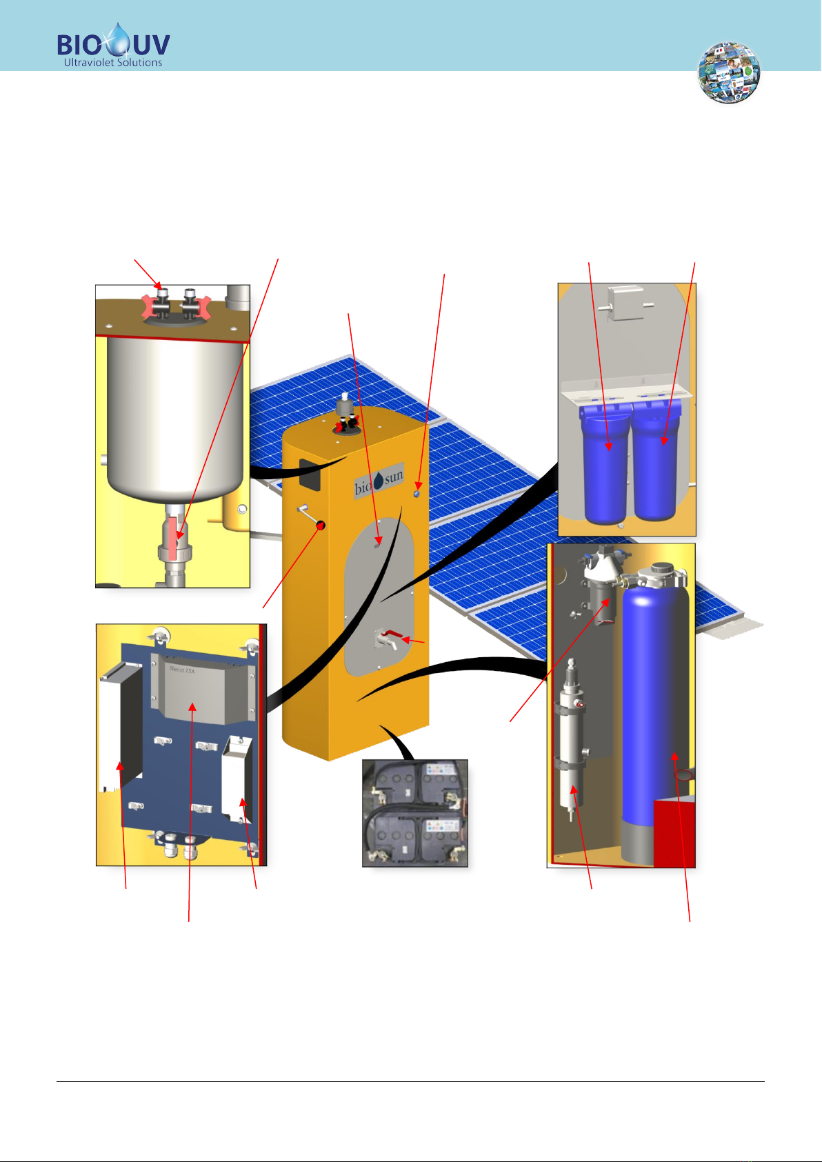
C. BIOSUNTERMINAL DESCRIPTION
1. Overview
Handle for Filtration /
Cleaning position
Inlet valve
Intensity regulator
UV Ballast
Converter
UV ON/OFF light
switch
Zeolithe filter
UV Reactor
Batteries (x2)
Water counter
Treated
water valve
Pump
Draining valve 10µm filter
Active carbon filter
BIOSUN-340_(Anglais) - DOC012466 - Ind. B03 - 21/06/2017 Copyright BIO-UV
Marque, Modèles et Brevets déposés - Produits exclusifs
Page 6
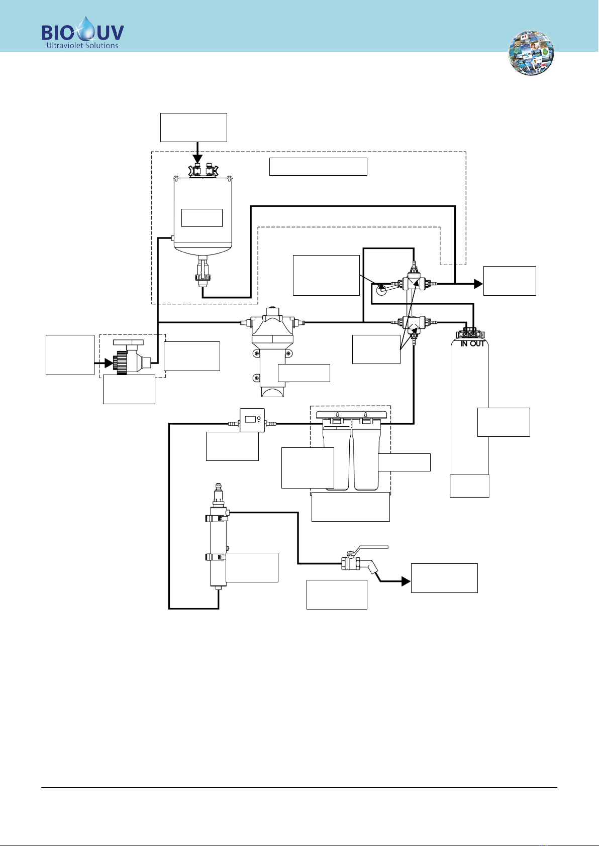
2. Hydraulicdiagram
With tank option
Without
tank option
Untreated
water inlet
Untreated
water
inlet
Draining
outlet
Treated water
outlet
Tank
Three
way valve
« Filtration /
cleaning »
handle
Zéolithe
filter
Pump
Manual
valve
10µm filter
Active
carbon
filter
Water
counter
UV
Reactor
Treated
water valve
Cartridge filters
option
BIOSUN-340_(Anglais) - DOC012466 - Ind. B03 - 21/06/2017 Copyright BIO-UV
Marque, Modèles et Brevets déposés - Produits exclusifs
Page 7
D. INSTALLATION GUIDE
1. Foreword
Read all the instructions in this manual before switching on
the reactor.
IMPORTANT: BIOSUN 340 is designed to be connected to a low pressure system (< 1 bar)
If the operating pressure exceeds 1 bar, the BIOSUN 85 model must be used
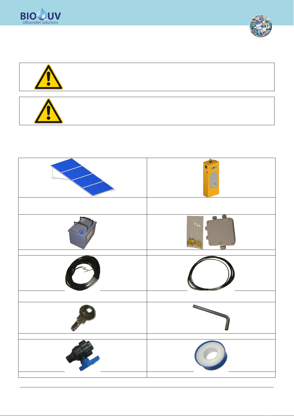
2. Detail of providedelements
Solar panels with frame (to be mounted and wired)
(The parts list of the frame supporting the solar panels is
specified on page 9.)
BIOSUN terminal
2 12V Batteries
Junction box with connecting lugs
Cables for terminal / solar panels connection
(Do not reduce length)
Cables to connect solar panels together
(Do not reduce length during wiring)
Switch key Anti-theft wrench
Supply valve (if no tank option) Teflon roll
BIOSUN-340_(Anglais) - DOC012466 - Ind. B03 - 21/06/2017 Copyright BIO-UV
Marque, Modèles et Brevets déposés - Produits exclusifs
Page 8
3. Mountingof photovoltaic panels
a.)
Preparation
Before starting mounting, the concrete foundation should have been done first.
a-1.
Description of the symbols used
Safetytips:
This symbol indicates a warning, which, if ignored, could result in risks to people or equipment. Read these passages
carefully.
Example:
Risk of injuries
•Risk of serious injury to the hands
•
Wear protective gloves!
Information
This symbol indicates information on the most appropriate procedure.
Example:
Use a screwdriver to tighten the screws
a-2.
Use a screwdriver to tighten the screws
When assembling the aluminium structure and the module, be sure to follow these safety tips:
Risks of cuts
•Cuts to the hands due to incorrectly deburred parts.
•Wear safety gloves!
Risks of burns
•Risk of burns from parts exposed to high heat.
•
Check the temperature of parts and wear gloves!
Risks of explosions
•Risk of explosion due to improper use of batteries
•Do not smoke or bring a naked flame near the batteries!
Risks of chemical burns
•The acid in the batteries can cause chemical burns.
•
Wear an apron and ant-acid gloves!
a-3.
Table for adjusting the solar panel tilt angle
LATITUDE TILT ANGLE
Latitude < 20° 15°
20° < latitude < 35° Latitude + 10°
Latitude > 35° Latitude + 15°
The minimum tilt angle value of 15° provides for "self-cleaning" of the photovoltaic panel and limits the risk of residual
moisture.
a-4.
Dimensions table
Foundation Fixing points Profiles length
F1 : 1844 mm A : 80 mm Profile P1 (2 parts) : 2340 mm
F2 : 1245 mm B : 380 mm Profile P2 (2 parts) : 802 mm
F3 : 263 mm C : 1300 mm Profile P3 (2 parts) : 300 mm
F4 : 720 mm D : 80 mm Profile P4 (2 parts) : 1013 mm
F5 : 525 mm E : 160 mm Profile P5 (1 part) : 640 mm
F : 120 mm
BIOSUN-340_(Anglais) - DOC012466 - Ind. B03 - 21/06/2017 Copyright BIO-UV
Marque, Modèles et Brevets déposés - Produits exclusifs
Page 9
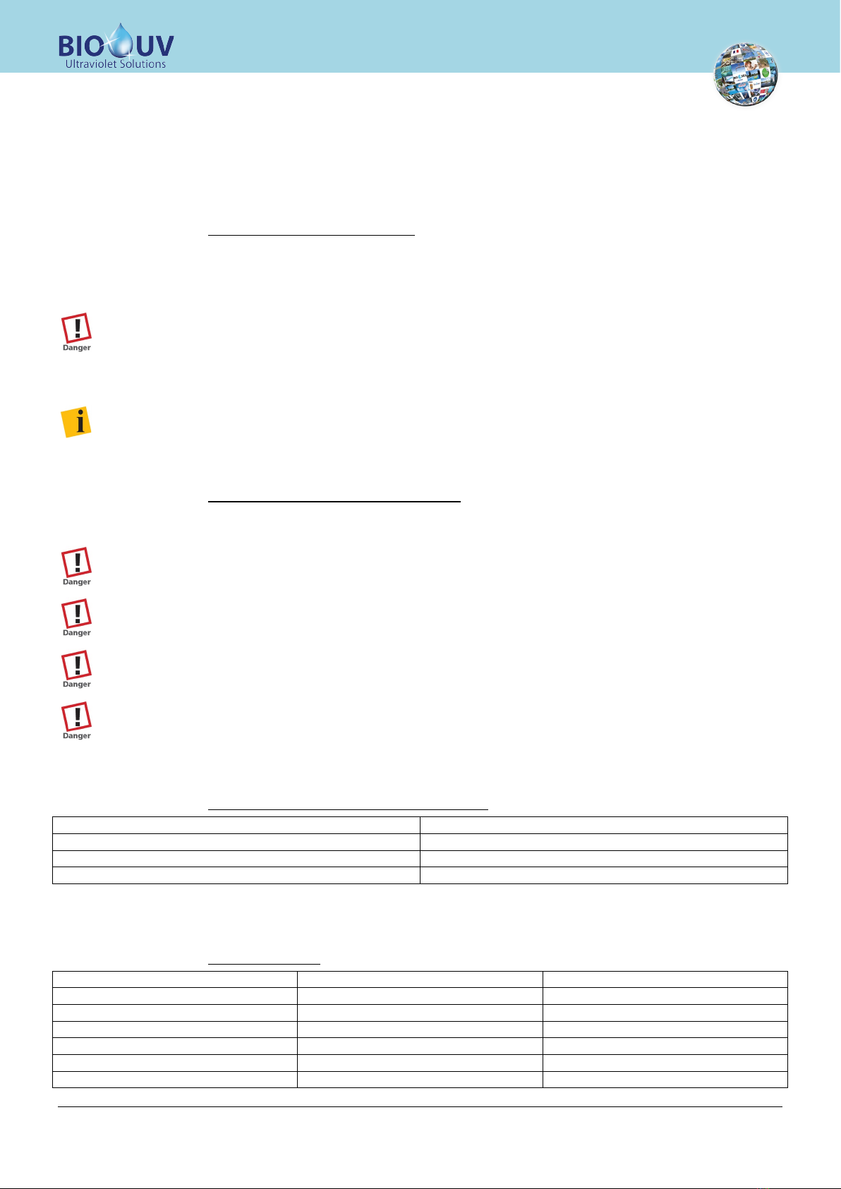
a-5.
Parts list
You will find the various parts of the structure supporting the modules
Rope clamp Clamping bolt Ring bolt Thimble Short screw
(20mm)
Short screw
(30mm) Nut HU M8 Flat washer L d=8 Tensioner Shackle
Large U profile Small U Profile I-module fixation T-module fixation Flat washer M
d=8
P1 type formed
section P1 type formed
section P1 type formed
section P1 type formed
section P1 type formed
section
a-6.
Required tools
The tools required to assemble the module support structure are indicated below
Spirit level Flat wrench (Size 13,
Size 10)
Cutting pliers Folding meter rule Allen wrench (Size 6)

BIOSUN-340_(Anglais) - DOC012466 - Ind. B03 - 21/06/2017 Copyright BIO-UV
Marque, Modèles et Brevets déposés - Produits exclusifs
Page 10
b.)
Assembly
b-1.
Foundations for the aluminium support structure
Pre-tighten the screws during the assembly period and firmly tighten only after assembling the whole structure
with its modules.
Risks of cuts
•Cuts to the hands due to structural parts not deburred.
•
Wear safety gloves!
When the concrete foundation is completely dry, drill the attaching holes in the floor.
•Using figure 01, measure and make marks on the concrete
•Drill the concrete with a hammer drill using a 12 mm diameter drill bit.
b-2.
Assembling the aluminium support structure
b-2.1.
Mounting the base
For this step, you will need four anchoring studs, two narrow U formed sections (3 holes) and two wide U formed sections
(5 holes).
Before attaching, make sure you have properly positioned the wide U formed sections for the part pointing
towards the foundations pole and the narrow U formed sections for the part pointing towards the equator (see
Figure 01, red circles).
•Fit the four anchoring bolts in the four holes drilled in step 2.1, and make sure to attach them the right way round!
•Fit the U formed sections to the threaded rods (see figure 02) of the anchoring studs and then bolt the whole
assembly together.
Ä
The bolts are now attached in the holes.
Foundation
Concrete
foundation
U TYPE PROFILE
Clamping screw
Nut
Foundation

BIOSUN-340_(Anglais) - DOC012466 - Ind. B03 - 21/06/2017 Copyright BIO-UV
Marque, Modèles et Brevets déposés - Produits exclusifs
Page 11
b-2.2.
Installing the two P2 type formed sections
In the next steps, install the P2 and P5 type formed sections. Figure 03 provides an overview of the structure showing the
use of the formed sections (red circles).
First assemble the three formed sections together on the floor. Then attach them to the foundations, otherwise the
screws cannot be tighten!
b-2.3.
Fitting the eye nuts to the P2 type formed sections
For this step, you will need four eye nuts (see figure 04, red circles), four L 8 mm dia plain washers, eight HU M8 nuts and
two P2 type formed sections.
Option: If you have the version with the GCB support (support for junction box), you also need to fit the support in
this step! (see next paragraph)
The following figure shows you what the structure should look like after this step.
•If you do not fit the GCB support - assemble the eye nuts (see figure 04).
Side view
Rear view
Rear viewCross-section view
Large
washer
Eye nut
Base plan for P2
type formed P2 type
Profile
Support for GCB (optional)

BIOSUN-340_(Anglais) - DOC012466 - Ind. B03 - 21/06/2017 Copyright BIO-UV
Marque, Modèles et Brevets déposés - Produits exclusifs
Page 12
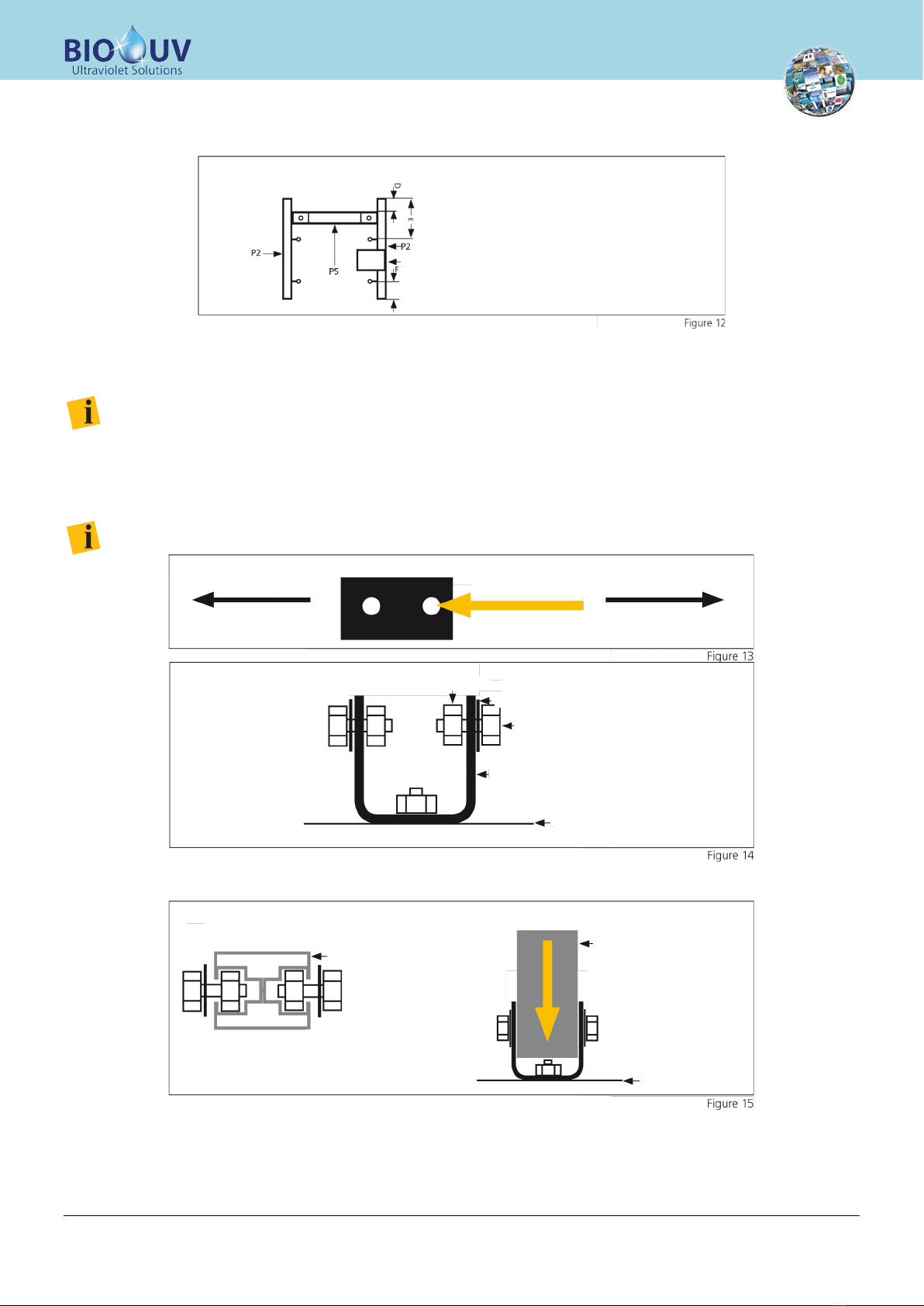
b-2.4.
Fitting the eye nuts and the GCB support
The eye nuts are fitted in the same way as in the previous step! But make sure to fit the support between the eye nuts on
the outside (rear view)
How to install the GCB support:
•Prepare two narrow U formed sections as shown in figure 05 (below).
•Fit the GCB support to the two U formed sections as shown in the following diagram (figure 06)
•After fitting the first eye nut, fit the GCB support with the two U formed sections to the two P2 type
formed sections (rear view) (see figure 07)
Nut Small washer
Short screw
U type Profile
U type formed section (side view)
U type formed section (side view)
GCB Support
Cross-sectional view from above
Floor plan for P2 type formed section
Floor plan for U type formed section
GCB plate support
BIOSUN-340_(Anglais) - DOC012466 - Ind. B03 - 21/06/2017 Copyright BIO-UV
Marque, Modèles et Brevets déposés - Produits exclusifs
Page 13
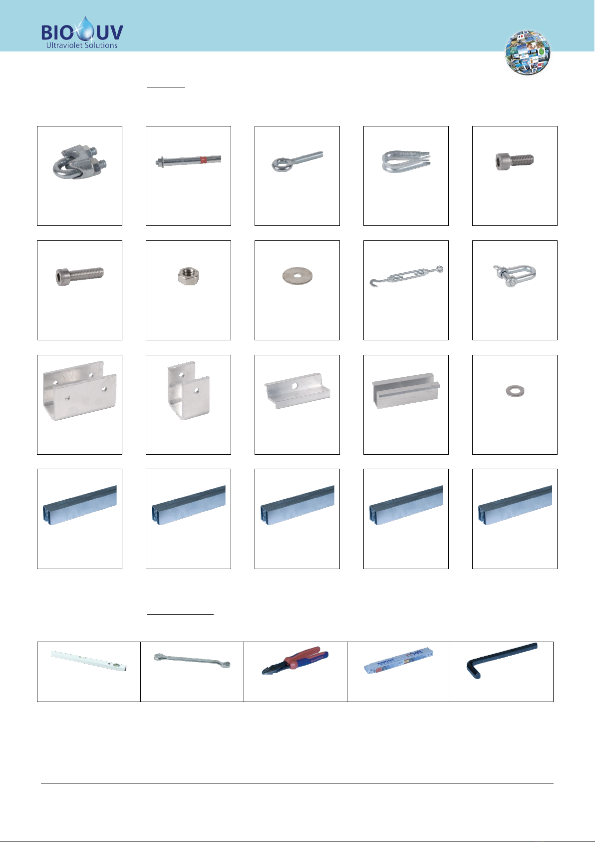
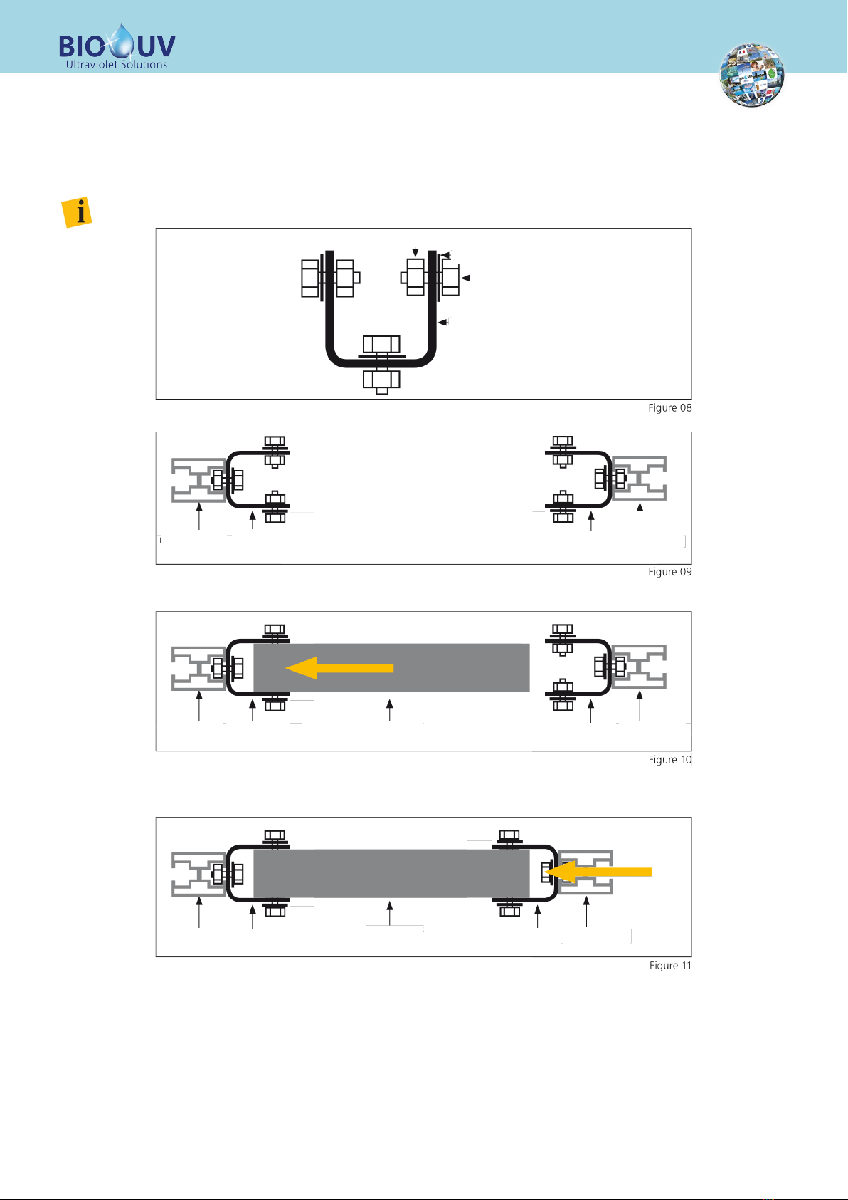
b-2.5.
Fitting the P5 type formed section
For this step you need the P5 type formed section, two narrow U formed sections, six short screws, six M plain washers d=
8 and six HU M8 nuts.
Figure 03 shows you where the formed sections are located in the overall construction (red circles)
•Prepare two narrow U formed sections as shown in the following figure (figure 08)
Do not tighten nuts at this point, as you will have to handle the formed sections in the next step!
•Fit the two U formed sections prepared with the two P2 type formed sections, as shown in figure 09.
•Attach the P5 type formed section to one of the U formed sections (see figure 10 below) - the attachment
is similar to the attachment you performed previously.
•Tighten the nuts of the U formed section, in which you attached the P5 type formed section
•Attach the P5 type formed section to the second U formed section, which is itself already attached to the
second P2 type formed section
Nut
Flat washer M d=8
Short screw
U type formed section
P2 formed
section
P2 formed
section
U formed
section U formed
section
P2 formed
section
P2 formed
section
U formed
section U formed
section
P5 formed
section
P2 formed
section
P2 formed
section
U formed
section
U formed
section
P5 formed
section
BIOSUN-340_(Anglais) - DOC012466 - Ind. B03 - 21/06/2017 Copyright BIO-UV
Marque, Modèles et Brevets déposés - Produits exclusifs
Page 14
•Tighten the nuts of the U formed section, in which you attached the P5 type formed section
Ä
Your structure should look as shown in the diagram below!
b-2.6.
Fitting the P2/P5 constructions to the foundations
Fit the screws, the nuts and the plain washers in the holes in the opposite direction to the equator of the wide U
formed sections!!! See figure below (figure 13)
•Fit the two short screws (20mm) in the "Pole" holes of one of the wide U formed sections that you have
already fitted to the foundations. You will need a nut and an M 8 mm dia plain washer for each screw.
Figure 14 shows how to assemble the bolts.
Do not tighten the screws at this point, as you will need to handle the formed sections in the next step!
•Repeat this procedure for the other U formed section!
•Attach the screws to the two sides of the P2 type formed section, as indicated in figure 15
•Make sure that the construction makes a right angle (90) relative to the foundation
•Tighten the screws on both sides
Ä
Both P2 formed sections are now firmly secured to the base (floor).
Rear view
GCB support (optional)
Equator
PoleIt is the hole on the right
HU M8 nut
Flat washer M8
20mm short screw
U formed section
Foundation
Cross-sectional view Front view
Base plan for the formed
section P2 type
P2 type formed section
Foundation
BIOSUN-340_(Anglais) - DOC012466 - Ind. B03 - 21/06/2017 Copyright BIO-UV
Marque, Modèles et Brevets déposés - Produits exclusifs
Page 15
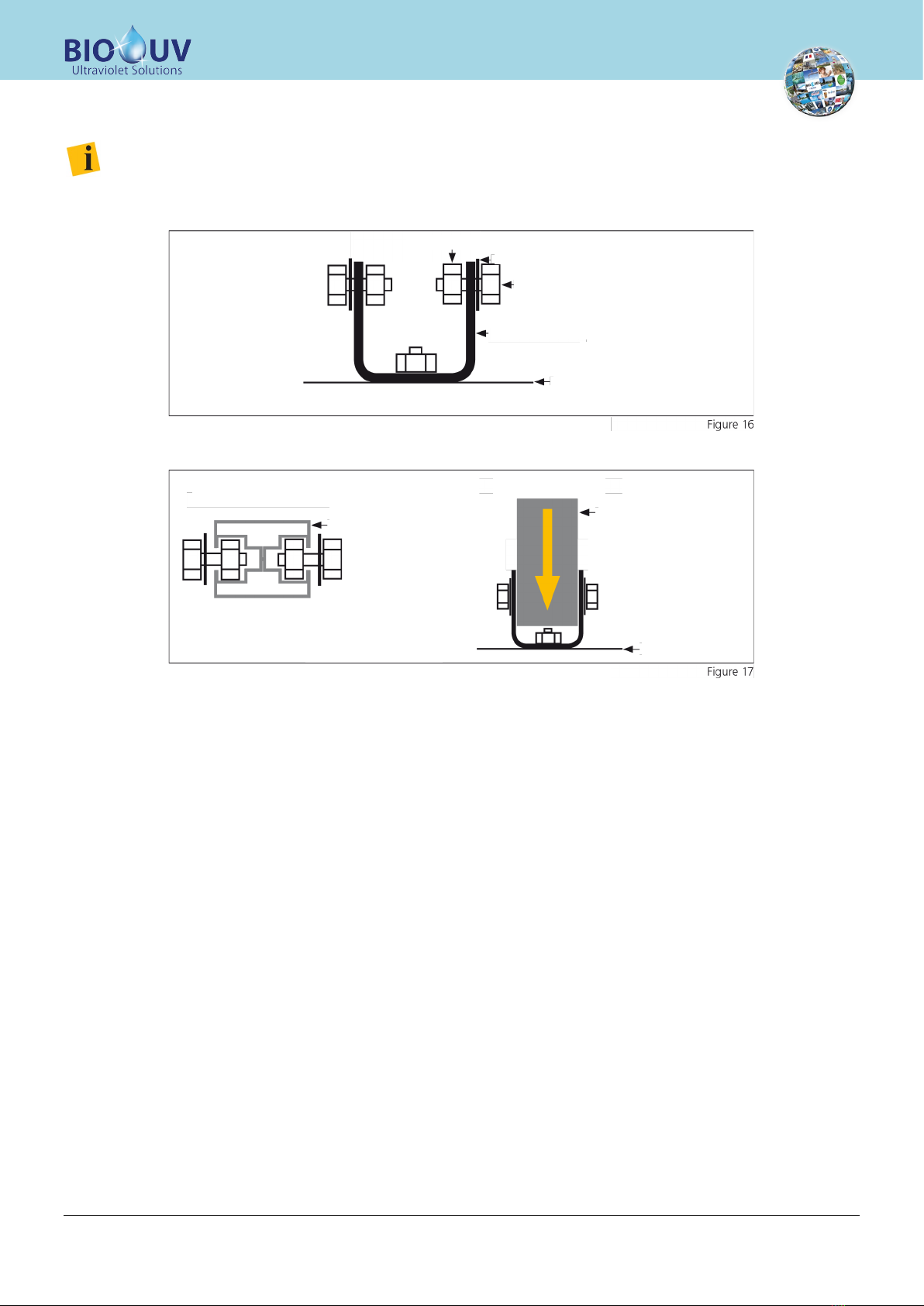
b-2.7.
Fitting the P3 type formed sections
Do not tighten the screws at this point, as you will need to handle the formed sections in the next step!
•Fit two short screws (20mm) to the U formed sections you previously fitted to the foundations. You will
need a nut and a small washer for each screw.
Figure 16 shows how to assemble the screws.
•Repeat this procedure for the other narrow U formed section!
•Attach the screws to the P3 type formed section as indicated in figure 17 on both sides
•Make sure that the construction makes a right angle (90) relative to the foundation
•Attach the screws on both sides
Ä
Both P3 formed sections are now screwed to the floor
Nut
Small washer
Short screw
U type formed section
Foundation
Cross-sectional view Front view
Base plan for the formed
section P2 type
P2 type formed section
Foundation

BIOSUN-340_(Anglais) - DOC012466 - Ind. B03 - 21/06/2017 Copyright BIO-UV
Marque, Modèles et Brevets déposés - Produits exclusifs
Page 16
b-2.8.
Preparing the P1 type formed sections
For this step, you will need P1 type formed sections, six narrow U formed sections, 18 short screws and 18 small washers.
Figure 18 shows you where the formed sections should be installed in the overall structure (red circles).
•Prepare six narrow U formed sections as shown in figure 19.
Do not tighten the screws at this point, as you will need to handle the formed sections in the next step!
•Install three of the prepared U formed sections to the first P1 type formed section (see figure 20) - Make
sure to comply with the distances A, B and C (see figure 21).
•Repeat this procedure with the other P1 type formed section
•Tighten the screws fitted to the P1 type formed sections
Ä
Both P1 type formed sections are now ready to be assembled to the P3 and P2/P5 type formed
section
Side view
Nut
Small washer
Short screw
U type formed section
P1 type formed
section
U type formed
section
U type formed
section
U type formed
section
U type formed
section
P1 type formed
section

BIOSUN-340_(Anglais) - DOC012466 - Ind. B03 - 21/06/2017 Copyright BIO-UV
Marque, Modèles et Brevets déposés - Produits exclusifs
Page 17
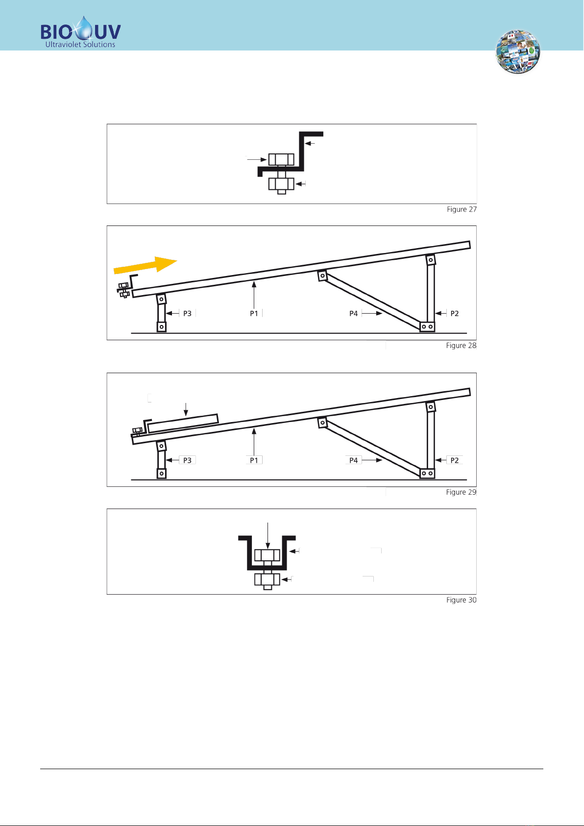
b-2.9.
Fitting the P4 type formed sections
For this step, you need P4 type formed sections, 4 small washers and 4 nuts.
Figure 22 shows where the formed sections are fitted in the overall structure (red circle).
•Fit the short screws (20mm) in the remaining hole in one of the wide U formed sections that you have
already attached to the foundations. You will need a nut and a small washer for each screw. Figure 23
shows how to assemble the screws.
Do not tighten the screws at this point, as you will need to handle the formed sections in the next step!
•Mount the Profile P4 into the U-Profile like shown in figure 15 (angle is not so important yet and will be
arranged in the next steps automatically
•Repeat this procedure for the other Profile P4
Ä
The Aluminum Support Structure is ready to mount the Profiles P1
Side view
Nut
Small washer
Short screw
U type formed section
Foundation

BIOSUN-340_(Anglais) - DOC012466 - Ind. B03 - 21/06/2017 Copyright BIO-UV
Marque, Modèles et Brevets déposés - Produits exclusifs
Page 18
b-2.10.
Fitting the P1 type formed sections
For this step, you will need the previously prepared P1 type formed sections.
•Fit the P1 type formed sections to the P4, P2 and P3 formed sections as shown in figure 24 below.
Slight differences can be balanced by adjusting the U formed sections. But make sure that the parts are fitted the
right way round!
BIOSUN-340_(Anglais) - DOC012466 - Ind. B03 - 21/06/2017 Copyright BIO-UV
Marque, Modèles et Brevets déposés - Produits exclusifs
Page 19
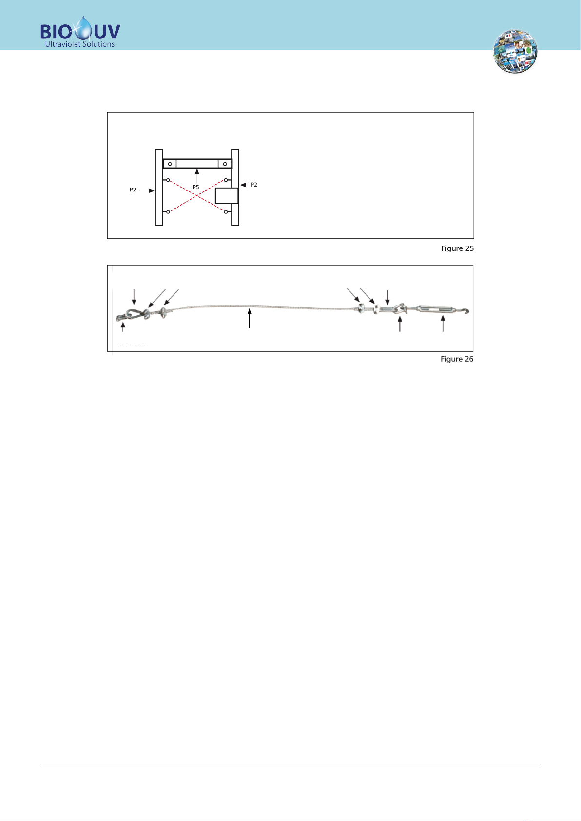
b-2.11.
Fitting the safety cables
For this step, you need four shackles, four core lugs, eight cable clamps, two turnbuckles and steel cable.
•Check the length between the eye nuts (diagonally), (see figure 25 - red lines)
•Assemble the wiring as shown in Figure 26, and make sure that they are the right length.
•Attach both cables as shown in figure 25 (red dashed lines) and tighten the cables using the tensioners
Rear view
Core terminal
lug
Core terminal
lug
Cable clamp Cable clamp
Shackles Shackles TensionerSteel cable
BIOSUN-340_(Anglais) - DOC012466 - Ind. B03 - 21/06/2017 Copyright BIO-UV
Marque, Modèles et Brevets déposés - Produits exclusifs
Page 20
b-2.12.
Fitting the photovoltaic modules
For this step, you will need fasteners for T and L type modules. Make sure that you have screws and nuts - long screws for
attaching T modules and short screws for attaching L modules.
•Prepare two L fasteners as shown in figure 27.
•Screw the L fasteners into each of the two P1 type formed sections as shown in figure 28.
•Fit the photovoltaic module to the two P1 type formed sections and tighten the L attaching screws (see
figure 29)
•Prepare two T fasteners (see figure 30)
Short screw
L module attachment
Nut
Solar panel
T module fastener
Long screw
Nut
Table of contents
Other BIO UV Water Filtration System manuals


Popular Water Filtration System manuals by other brands

Ocean Protect
Ocean Protect OceanGuard installation guide

Weller
Weller FT LASERLINE Series Translation of the original instructions

Pelgrim
Pelgrim PRS2 installation instructions

Premier Tech Aqua
Premier Tech Aqua Rewatec Fl-1 Installation and operating instructions

Insignia
Insignia NS-APFL2 Quick setup guide

SuperFish
SuperFish Deco-Filter Amphora user manual

Aquadistri
Aquadistri SuperFish Aqua Pro Feeder quick start guide

IBC Water
IBC Water AFB16-180 Installation & operating instructions

ProSystems
ProSystems 38247 owner's manual

Hayward
Hayward Super Star Clear C2000 owner's guide

Aquacal
Aquacal ST-220 owner's manual

Spasciani
Spasciani 100 Series quick start guide


