Fumex FA1 Series User manual

FA1 Series
Air Filtration System
Operations Manual
READ AND SAVE THESE INSTRUCTIONS
WARNING:
Disconnect from power supply before performing maintenance procedures
such as cabinet cleaning, changing filters or servicing of electric motor or
other electric components
WARNING:
To reduce the risk of fire or electric shock, do not use this fan with any solid-
state speed control device.
WARNING:
For general ventilating use only. Do not use to exhaust hazardous or explosive
materials or vapors.
WARNING:
Use only a 10-Amp fuse.
CAUTION:
Do not operate without having all filters in place.
Do not operate any fan with a damaged cord or plug. Discard fan or return to an
authorized service facility for examination and/or repair.
Do not run cord under carpeting. Do not cover cord with throw rugs, runners or
similar coverings. Arrange cord away from traffic area and where it will not be
tripped over.

2
GETTING STARTED
Initial set-up
1. Open all cartons and locate inlet, hose, hose clamps and wheels.Refer to Table 1 for the applicable part
numbers for your model.
2. Remove ALL filters and packing materials from cartons and the unit cabinet.
3. Place the unit on its side and install wheels in the bottom plate.
4. Attach the inlet to the top of the lid with the six screws provided.
5. Remove plastic wrap from gas/odor filter.
6. Carefully remove perforated cardboard from top and bottom of FA101D filter to expose “Green” media.
7. Place FA101D gas/odor filter into bottom of cabinet (NOTE: Pay attention to direction of airflow arrow).
8. Place FA100 HEPA filter on top of gas/odor filter (NOTE: Pay attention to direction of airflow arrow).
9. Place the FA102B pre-filter on top of the HEPA filter.
10. Close and latch the lid.
11. Attach power cord to the power receptacle located on the lower rear of the cabinet.
Locating the air cleaner
Placing the FA1 unit as close as possible to the pollution source reduces the amount of ducting needed, reduces
back-pressure, lowers power consumption, and improves overall performance. Placement should minimize hose
length and the number of bends. Use capture hoods with high efficiency entry whenever possible. The unit
exhausts through the bottom panel make sure to allow for adequate ventilation.
Inlet hose attachment
The FA1 unit ships standard with a 1 x 2”, 2 x 2” or 1 x 3” inlet. Attach flex hose over the metal air inlet tube and
tighten securely with the stainless-steel clamp. Connect the hose to a Fumex suction hood or place as close as
possible to the pollution source.
Electric power
FA1 is manufactured with a universal blower/motor assembly (90-250/1/50-60) and must only use a 10-Amp fuse.
Default power cord/plug is US (120V). Contact Fumex for additional information or options.
Confirm that correct power supply is available.

3
CONTROLS
On/Off Switch
Simple one touch controls – The green light above the POWER button will illuminate confirming power to the
unit.
Blower/Fan
The FA1 utilizes a variable speed blower with three speed settings. Press the up and down arrow buttons to
increase/decrease blower speed. A green light next to the specific speed (Low, Med, or High) will indicate speed
setting. In the case of a blower failure, all 3 blower speed lights will flash. To reset the blower’s internal thermal
protection, disconnect the unit momentarily from its power source and reconnect. If the lights continue to flash
contact Fumex LLC. for replacement information.
Filter monitoring
The FA1 utilizes a pressure differential switch to monitor the status of the particulate filters. The system monitors
across all filters simultaneously and the Red “FILTER” light will illuminate when one or more filters need to be
replaced. The recommended procedure is to first replace the Pre-Filter and then press the “FILTER RESET”
button. If the light remains illuminated or turns off and comes back on then replace the HEPA filter and press the
“FILTER RESET” button.
The FA1 contains a VOC sensor to detect odors/gases in the exhaust stream. When the gas/odor filter becomes
saturated and breakthrough of the VOC occurs the “GAS” warning light will illuminate.
GENERAL FILTER CARE
Fumex’s FA1 air purifier features a multi-stage filtration system designed to remove a wide range of pollutants
from the process plume in an extremely efficient, cost-effective manner. The system utilizes a pressure
differential switch to indicate blocked / clogged filters. Once the warning lights illuminate, filters should be
checked and clogged filters replaced.
STANDARD FILTERS:
Part # FA102B Pre-filter Assembly
The pre-filter assembly is the first stage in the filtration process. The assembly is composed of high capacity
merv 11 rated filter media protected by polyester pre-filter. Unique design minimizes operator/maintenance
personnel exposure to contaminants.
Replacement:
The unique design of the pre-filter allows the filter to be changed as a complete unit or in heavy dust applications
the polyester pre-filter can be removed independently. Contact Fumex LLC. regarding any questions/assistance.

4
Part # FA100 HEPA Filter
The HEPA filter is 99.97% efficient in removing particles as small as 0.3µfrom an airstream.
Particles of this size are respirable and can cause significant respiratory problems.
Replacement:
A HEPA’s service life is determined by the volume of sub-micron particles remaining in the airstream after
passing through the pre-filters. When properly protected, and depending on loading, HEPA filters often provide
months of service. Average service life is 2-4 months.
Part # FA101D Gas/Odor Filter
Most process plumes contain several gases, some odorous – some not, some toxic at elevated concentrations –
some completely harmless regardless of concentration. To ensure employee safety the type and concentration
of pollutants must be determined. Please contact Fumex Engineering for filter selection assistance. These filters
utilize a blended activated carbon and activated alumina impregnated with KMnO4 filter to capture and treat
gases/odors. This combination of materials provides protection across a broad range of gases commonly found
in industrial manufacturing processes.
GENERAL MAINTENANCE
1) The blower motor is a sealed unit, 24,000 hr. MTBF rated. It is permanently lubricated and does not require
oiling – keep it free of dust accumulations to prevent overheating.
2) Remove any loose accumulations of dust/debris from the air filter chamber periodically.
“This product employs overload protection (fuse). A blown fuse indicates an overload or short-circuit situation. If
the fuse blows, unplug the product from the outlet. Replace the fuse as per the user servicing instructions (only
10-Amp fuse) and check the product. If the replacement fuse blows, a short circuit may be present and the
product should be discarded or returned to an authorized service facility for examination and/or repair”.
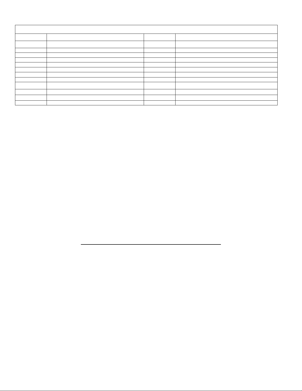
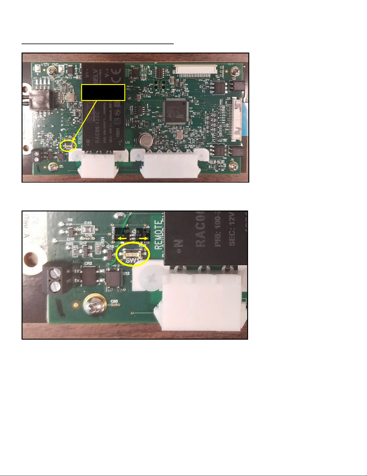
Remote Interface and Connectivity Function
The FA1 can be supplied with an optional interface package providing remote start/stop and filter monitoring
capabilities (Part # FA228). Please see instructions below for Relay Activation/De-Activation procedures and
refer to the drawing in Figure 1 for remote connections.
WARNING
“To Prevent the Risk of Electrical Shock, Connect Remote Interface
Cable to 24v, Class 2 Power Supply Only”
WARNING
“Disconnect From All Power Supplies Before Servicing”

5
Replacement Parts
Part #
Item
Part #
Item
Cabinetry
Electrical
FA108
Wheels, standard
FAAU500
Universal blower motor / assembly – 90-250/1/50-60
FA109
Vibration Isolators
FA004
Control board assembly
FA117
Cabinet latch
FA113
Fuseholder
FA118
Cabinet hinge
FA114
Fuse, 10 amp
FA106A
Flanged air inlet 3”∅
FA115
Cordset (120vac)
FA106B
Flanged air inlet 2 x 2”∅
FA115B
Cordset (230vac)
FA106C
Flanged air inlet 1 x 2”
Filters
Gas/ Odor Filters
FA102B
Pre-Filter
FA101D
Blended carbon media – 2”
FA103
Polyester pre-filter
FA100
HEPA Filter – 6”
Table 1
Warranty and Liability limitations:
Fumex FA1 air cleaners are guaranteed for 24 months from date of invoice to be electrically and mechanically sound. This warranty covers the material
and workmanship only. Any defective item will be repaired or replaced, at our option, free of charge provided it has not been misused, abused, or
otherwise damaged and is returned PREPAID to:
Fumex, LLC. 1150 Cobb International Pl., Kennesaw, GA 30152
There are no warranties which extend beyond the descriptions set forth in this warranty, notwithstanding any knowledge of Fumex, LLC. regarding the
use or uses intended to be made of goods, proposed changes or additions to goods, or any assistance or suggestions that may have been made by
Fumex personnel. Customer is responsible for determining the suitability of Fumex products for customer’s use or resale, or for incorporating them into
objects or applications which customer designs, assembles, constructs or manufactures.
Fumex reserves the right to discontinue any item and to make changes in the specifications, terms and conditions or prices at any time without prior
notice. Information furnished in the specifications is believed to be accurate and reliable at time of printing, however Fumex accepts no responsibility for
product use, or the effect of future design or specification changes.
For Assistance or Technical Support please Contact Fumex LLC.
phone 770-514-7907 fax 770-514-1547
USA toll-free 800-432-7550
www.fumexinc.com
Fumex, LLC.
1150 Cobb International Place
Kennesaw, GA USA 30152
Fumex, LLC., 2017, all rights reserved.
Specifications subject to change without notice

6
RELAY ACTIVATION PROCEDURES FOR FA1 UNITS
CAUTION
DO NOT WORK ON PANEL WITH POWER APPLIED!
1. Disconnect all power sources from FA1 unit.
2. Remove the 8 screws securing the bottom panel and gently pry bottom panel loose.
3. Locate relay activation switch on the rear of the control panel as shown in Figure 2.
4. Flip the Relay Activation Switch to the “ON” position as indicated in Figure 3.
5. Reinstall bottom panel using the 8 screws removed in step 2.
6. Apply incoming power to the unit by connecting the power cord and turning the power switch located near
the power cord on. Make sure the blower is not running and the green power light is off. This is called the
“Soft On” state.
7. Now that the physical switch is activated and the unit is in the “Soft On” state, the software will need to be
reprogramed via a flash drive with a configuration file and the USB port on the control board. (Contact Fumex
to acquire the correct configuration file for your unit).
8. Reprogram the software by changing the “remoteSwitchOnly” setting in the configuration file to “1”. This
will lock out the Control Board power button. The ON/OFF function will only be able to be controlled
remotely.
9. After changing and saving the configuration file, plug the flash drive into the USB port on the front of the
control board. (Make sure the unit is in the “Soft On” state before plugging in the flash drive.)
10. After the reprogramming is complete the light above the USB port will turn green and remain lit until the flash
drive is removed from the USB port.
11. Remove the flash drive and apply 0-24 VDC to the start relay according to the wiring diagram in Figure 3 to
start the unit.
Once the relay activation switch is turned on and the configuration file has been
reprogrammed the unit will only start by applying the proper voltage to the
start/stop relay.

7
RELAY DE-ACTIVATION PROCEDURES FOR FA1 UNITS
CAUTION
DO NOT WORK ON PANEL WITH POWER APPLIED!
1. Disconnect all power sources from FA1.
2. Remove the 8 screws securing the bottom panel and gently pry bottom panel loose.
3. Locate relay activation switch on the rear of the control panel as shown in Figure 1.
4. Flip the Relay Activation Switch to the “OFF” position as indicated in Figure 2.
5. Reinstall bottom panel using the 8 screws removed in step 3.
6. Apply incoming power to the unit by connecting the power cord and turning the power switch located near
the power cord on. Make sure the blower is not running and the green power light is off. This is called the
“Soft On” state.
7. Now that the physical switch is activated and the unit is in the “Soft On” state, the software will need to be
reprogramed via a flash drive with a configuration file and the USB port on the control board. (Contact Fumex
to acquire the correct configuration file for your unit).
8. Reprogram the software by changing the “remoteSwitchOnly” setting in the configuration file to “0”. This
will unlock the Control Board power button. The ON/OFF function will only be able to be controlled by the
front panel on the unit.
9. After changing and saving the configuration file, plug the flash drive into the USB port on the front of the
control board. (Make sure the unit is in the “Soft On” state before plugging in the flash drive.)
10. After the reprogramming is complete the light above the USB port will turn green and remain lit until the flash
drive is removed from the USB port.
11. Remove the flash drive and start the unit as described in the “Controls” section.
Once the relay activation switch is turned off and the configuration file has been
reprogrammed the unit will only start by using the front control panel. All relays
will become non-functional.

8
DRAWINGS AND FIGURES
Figure 1

9
DRAWINGS AND FIGURES
Figure 2
Figure 3
ON
OFF
Relay Activation
Switch
Other manuals for FA1 Series
1
This manual suits for next models
7
Table of contents
Other Fumex Water Filtration System manuals
Popular Water Filtration System manuals by other brands

KWC
KWC PURESTREAM Installation and instruction manual

aquamanta
aquamanta EFX 600 instruction manual

KENT
KENT Elegant Lite Mineral RO Instruction handbook

Clean Water Systems
Clean Water Systems Pro?OX 2510 Installation & starting guide

eSpring
eSpring 11-0192-CA owner's manual

Pentair
Pentair IntelliChlor IC20 Installation and user guide