BIOCHEM microSpan 3040G User manual

microSpan
3040G
PULSE
OXIMETER
OPERATOR’S
MANUAL
~
BIOCHEM
NAS
BIOCHEM
INTERNATIONAL
INC.

Warnings
n
Federal
law
restricts
the
use
or
sale
of
this
device
by,
or
on
the
order
of,
a
physician.
Verify
that
the
3040G
Oximeter
is
set
to
the
proper
AC
line
voltage
setting
for
your
installation.
The
AC
line
voltage
setting
is
shown
on
the
rear
panel
of
the
3040G
Oximeter.
If
the
AC
line
voltage setting
is
incorrect,
do
not
use
the
3040G
Oximeter.
Contact
an
authorized
service
center.
The
3040G
Oximeter
is
intended
for
use
by
persons
trained
in
professional
health
care.
The
operator
must
be
thoroughly
familiar
with
the
information
in
this
manual before
using
the
instrument.
This
device
should
not
be
used
in
the
presence
of
flammable
anesthetics.
Operation
may
be
affected
in
the
presence
of
strong
electromagnetic
sources,
such
as
electrosurgery
equipment.
Operation
may
be
affected
in
the
presence
of
imaging
equipment,
such
as
Magnetic
Resonance
Imaging
(MRI),
and
Computed
Tomagraph
(CT)
devices,
etc.
It is
the
facility's
responsibility
to
verify
performance
prior
to
installing
equipment
in
any
of
these
environments.
Do
not
autoclave,
ethylene
oxide
sterilize,
or
immerse
in
liquid.
Unplug
before
cleaning
or
disinfecting.
Significant
levels
of
dysfunctional
hemoglobins,
such
as
carboxyhemoglogin
or
methemoglobin,
will
affect
the
accuracy
of
the
Sa02
measurement.
Operation
may
be
affected
in
the
presence
of
high
ambient
light.
Shield
the
probe
area
(with
a
surgical
towel,
for
example)
if
necessary.
Dyes
introduced
into
the
bloodstream,
such
as
methylene
blue,
indocyanine
green,
indigo
carmine,
and
flourescein,
may
cause
an
inability
to
determine
accurate
Sa02
readings.
Any
condition
which
restricts
blood
flow,
such
as
use
of
a
blood
pressure
cuff
or
extremes
in
systemic
vascular
resistance,
may
cause
an
inability
to
determine
accurate
pulse
and
Sa02
readings.
WARNING:
ELECTRICAL
SHOCK
HAZARD
when
covers
are
removed.
Do
not
remove
covers.
Refer
servicing
to
qualified
personnel.

Proprietary
Notice
Information
contained
in
this
document
is
copyrighted
by
Biochem
International
Inc.
and
may
not
be
duplicated
in
full
or
part
by
any
person
without
prior
written
approval
of
Biochem
International
Ine. Its
purpose
is
to
provide
the
user
with
adequately
detailed
documentation
to
efficiently
install,
operate,
maintain,
and
order
spare
parts
for the
equipment
supplied.
Every
effort
has
been
made
to
keep
the
information
contained
in
this
document
current
and
accurate
as of
the
date
of
publication
or
revision.
However,
no
guarantee
is
given
or
implied
that
the
document
is
error
free
or
that
it
is
accurate
with
regard
to
any
specification.
Limited
Warranty
Biochem
International
Inc.
warrants
each
new
Oximeter
to be
free
from
defects
in
workmanship
and
materials
under
normal
use
and
service
for
a
period
of
one
(1)
year from
the
date
of
shipment,
and
sensors
and
patient
cables
for
a
period
of
90
days
from
shipment.
Biochem
International
Inc.’s
sole
obligation
under
this
warranty
will
be
to
repair
or
replace,
at
its
option,
products
which
prove
to
be
defective
during
the
warranty
period.
The
foregoing
shall
be
the
sole
warranty
remedy.
Except
as
set
forth
herein,
seller
makes
no
warranties,
either
expressed
or
implied,
including
the
implied
warranties
of
merchantability
and
fitness
for
a
particular
purpose.
No
warranty
is
provided
if
the
products
are
modified
without
the
express
written consent
of
Biochem
International
Inc.,
and
seller
shall
not
be
liable
in
any
event
for
incidental
or
consequential
damage.
This
warranty
is
not
assignable.
Service
Support
Repairs
of
Biochem
International
Inc.’s
instruments
under
Warranty
must
take
place
at
authorized
service
centers.
When
calling
Biochem
to
request
service,
have your
monitor’s
model
and
serial
number
ready.
If
you
need
to
ship
the
monitor,
special
packing
is
required
to
prevent
shipping
damage.
All
accessories
should
accompany
the
instrument
and
shipping
costs
must
be
prepaid.
Biochem
International
Inc.
W238
N1650
Rockwood
Drive
Waukesha,
WI
53188-1199
(414)
542-3100

Table
of
Contents
10
12
17
18
19
20
Warnings
Table
of
Illustrations
General
Description
Theory
of
Operation
Front
Panel
Displays,
Indicators,
and
Keys
Rear
Panel
Connectors
and
Switch
Alarms
and
Indicators
12
Patient
Alarms
and
Indicators
System Alarms
and
Indicators
Using
the
3040G
Oximeter
13
Setting
Up
Starting
Attaching
the
Sensor
14
Verifying
the
Sensor
Placement
Measuring
the
Pulse
Rate
and
Sa02
Setting
the
Alarms
15
Interpreting
the
Patient
Alarms
Adjusting
the
Audio
Volume
Stopping
User’s
Maintenance
17
Cleaning
and
Disinfecting
Charging
the
Battery
Long
Term
Storage
Servicing
the
Monitor
18
Troubleshooting
Guide
Supplies
and
Accessories
19
Standard Supplies
and
Accessories
Optional Supplies
and
Accessories
Product
Specifications
20
General
Power
Requirements
Environmental
Specifications
Table
of
Illustrations
Page
Contents
6
Figure
1.
Composite
Illustration.
9
Figure
2.
Front
Panel
Displays,
Indicators,
and
Keys.
11
Figure
3.
Rear
Panel
Connectors
and
Switch.
16
Figure
4.
Finger
Probe
Application
for
Adults.
16
Figure
5.
Universal
"Y"
Probe
Application
for
Adults
-
Ear.
16
Figure
6.
Universal
"Y"
Probe
Application
for
Adults
-
Finger.
16
Figure
7.
Universal
"Y"
Probe
Ear
Clip
Attachment.
16
Figure
8.
Universal
"Y"
Probe
Application
for
Infants
-
Hand.
16
Figure
9.
Universal
“Y"
Probe
Application
for
Infants
-
Foot.

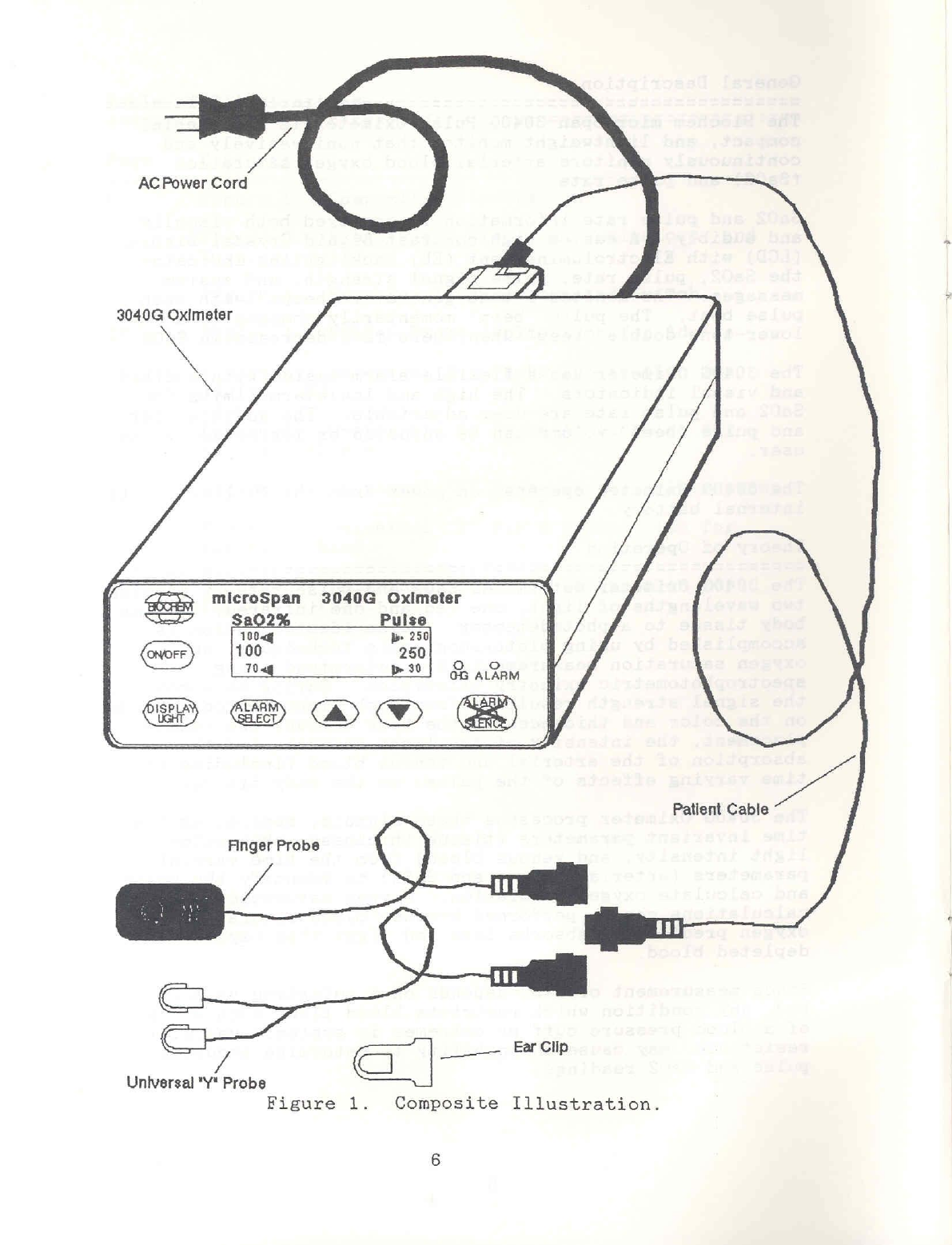
compact,
and
lightweight
monitor
that
noninvasively
and
continuously
monitors
arterial
blood
oxygen
saturation
(Sa02)
and
pulse
rate.
8802
and
pulse
rate
information
is
conveyed
both
visually
and
audibly.
A
custom
high
contrast
Liquid
Crystal Display
(LCD)
with
Electroluminescent
(EL)
backlighting
indicates
the
Sa02,
pulse
rate,
pulse
signal
strength,
and
system
messages.
The
monitor’s
tone
generator
“beeps”
with each
pulse
beat.
The
pulse
"beep"
momentarily
changes
to
a
lower-tone
double
“beep”
when
there
is
a
decrease
in
Sa02.
The
3040G
Oximeter
has
a
flexible
alarm
system
with
audible
and
visual
indicators.
The
high
and
low
alarm
limits
for
Sa02
and
pulse
rate
are
user
adjustable.
The
audible
alarm
and
pulse
"beep"
volume
can
be
adjusted
or
inhibited
by
the
user.
The
3040G
Oximeter
operates
on
power
from
the
AC
line
or
its
internal
battery.
Theory
of
Operation
The
3040G
Oximeter
determines
two
wavelengths
of
light,
one red
and one
infrared,
through
body
tissue
to
a
photodetector.
Pulse
identification
is
accomplished
by
using
plethysmographic
techniques,
and
oxygen
saturation
measurements
are
determined
using
spectrophotometric
oximetry
principles.
During
measurement,
the
signal
strength
resulting
from
each
light
source
depends
on
the
color
and
thickness
of
the
body
tissue,
the
sensor
placement,
the
intensity
of
the
light
sources,
and the
absorption
of
the
arterial
and
venous
blood
(including
the
time
varying
effects
of
the
pulse)
in
the
body
tissues.
The
3040G
Oximeter
processes
these
signals,
separating
the
time
invariant
parameters
(tissue
thickness,
skin
color,
light
intensity,
and
venous
blood)
from
the
time
variant
parameters
(arterial
volume
and
Sa02)
to
identify
the
pulse
and
calculate
oxygen
saturation.
Oxygen
saturation
calculations
can
be
performed
because
blood
saturated
with
oxygen
predictably
absorbs
less
red
light
than
oxygen
depleted
blood.
Since
measurement
of
Sa02
depends
on
a
pulsating
vascular
bed,
any
condition
which
restricts
blood
flow,
such
as
use
of
a
blood
pressure
cuff
or
extremes
in
systemic
vascular
resistance,
may
cause
an
inability
to
determine
accurate
pulse
and
Sa02
readings.
ta
AC
Power
Cord
3040G
Oximeter
AR
microSpan
3040G
Oximeter
+
Patient
Cable
Finger
Probe
/
/
а
|
____
ЕАСИ
Universal
"Y"
Probe
Figure
1.
Composite
Illustration.
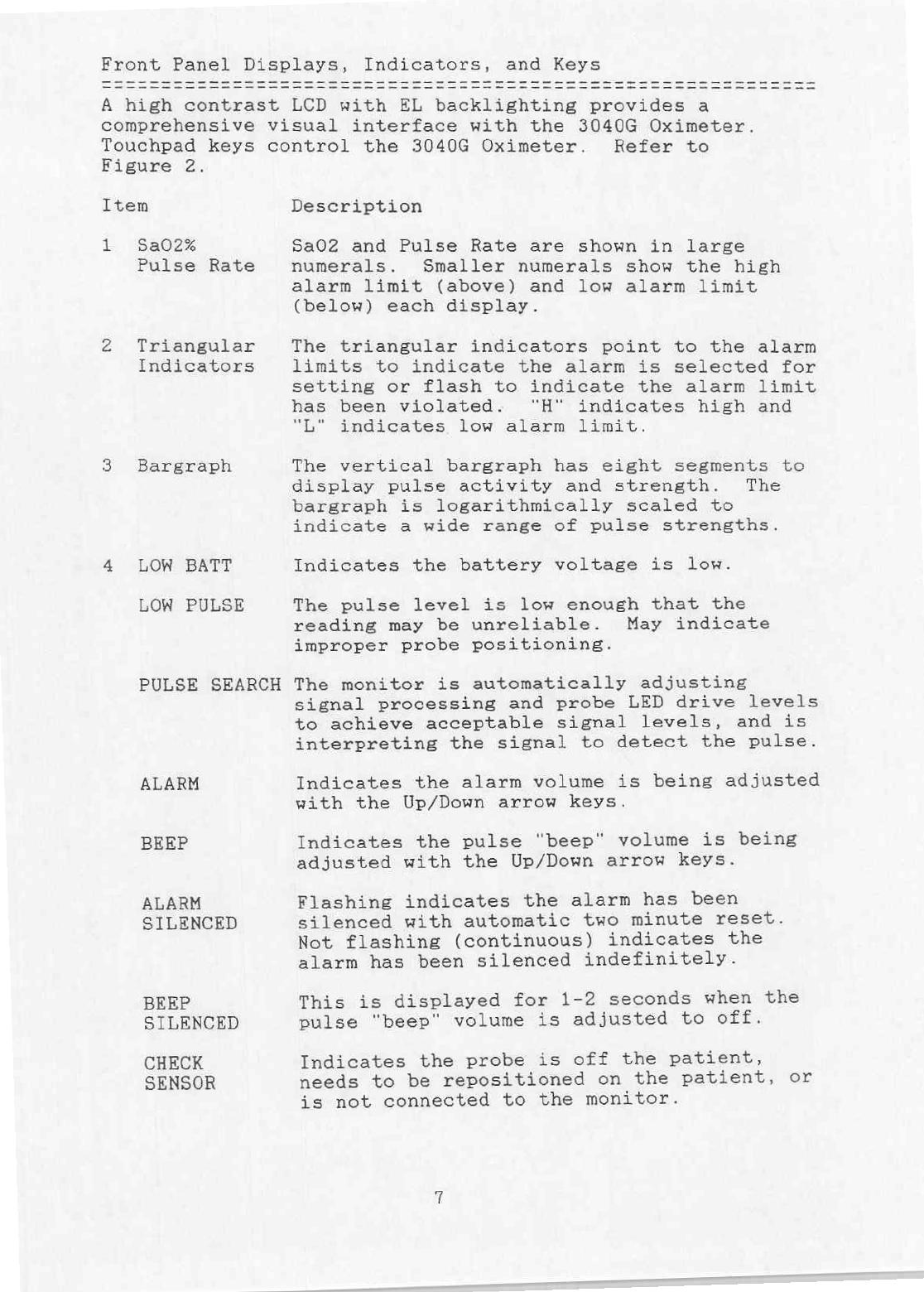
Front
Panel
Displays,
Indicators,
and
Keys
A
high
contrast
LCD
with
EL
backlighting
provides
a
comprehensive
visual
interface
with
the
3040G
Oximeter.
Touchpad
keys
control
the
3040G
Oximeter.
Refer
to
Figure
2.
Item
Description
1
Sa02%
Sa02
and
Pulse
Rate
are
shown
in
large
Pulse
Rate
numerals.
Smaller
numerals
show
the
high
alarm
limit
(above)
and
low
alarm
limit
(below)
each
display.
2
Triangular
The
triangular
indicators
point
to
the
alarm
Indicators
limits
to
indicate
the
alarm
is
selected
for
setting
or
flash
to
indicate
the
alarm
limit
has
been
violated.
"“H"
indicates
high
and
“L"
indicates
low
alarm
limit.
3
Bargraph
The
vertical
bargraph
has
eight
segments
to
display
pulse
activity
and
strength.
The
bargraph
is
logarithmically
scaled
to
indicate
a
wide
range
of
pulse
strengths.
4
LOW
BATT
Indicates
the
battery
voltage
is
low.
LOW
PULSE
The
pulse
level
is
low
enough
that
the
reading
may
be
unreliable.
May
indicate
improper
probe
positioning.
PULSE
SEARCH
The
monitor
is
automatically
adjusting
signal
processing
and
probe
LED
drive
levels
to
achieve
acceptable
signal
levels,
and
is
interpreting
the
signal
to
detect
the
pulse.
ALARM
Indicates
the
alarm
volume
is
being
adjusted
with
the
Up/Down
arrow
keys.
BEEP
Indicates
the
pulse
“beep”
volume
is
being
adjusted
with
the
Up/Down
arrow
keys.
ALARM
Flashing
indicates
the
alarm
has
been
SILENCED silenced
with
automatic
two
minute
reset.
Not
flashing
(continuous)
indicates
the
alarm
has
been
silenced
indefinitely.
BEEP
This
is
displayed
for
1-2
seconds
when
the
SILENCED
pulse
“beep”
volume
is
adjusted
to
off.
CHECK
Indicates
the
probe
is
off
the
patient,
SENSOR
needs
to
be
repositioned
on
the
patient,
or
is
not
connected
to
the
monitor.
5
ON/OFF
6
DISPLAY
LIGHT
7
ALARM
SELECT
8
Up/Down
Arrows
9
ALARM
SILENCE
10
ALARM
11
CHG
Turns
the
monitor
on
and
off.
The
internal
battery Charger
is
on
when
AC
power
is
supplied
and
the
BATTERY
Switch
is
in
the
NORMAL
position.
Toggles
the
display
backlight
on
and
off.
Pressing
ALARM
SELECT
steps
through
each
of
the
four
alarm
limits
for
setting,
and
back
to
none
selected.
If
either
the
Up/Down
arrows
or
the
ALARM
SELECT
key
is
not
pressed
for
approximately
20
seconds,
the
monitor
returns
to
none
selected.
When
an
alarm limit
is
not
selected,
these
keys
increase/decrease
either
the
alarm
volume
(when
the
alarm
is
not
silenced)
or
the
pulse
"beep"
volume
(when
the
alarm
is
silenced).
When
an
alarm limit
is
selected,
these
keys
control
scrolling
up
and
down
through
the
alarm
limits’
setting.
The
Up/Down
Arrow
keys
are
also
used
to
select
4
or
16
pulse
averaging
for
%Sa02
measurement
(the
default
is
8
pulse
averaging).
Refer
to
the
"Starting"
section
on
page
13
for
details.
Pressing
ALARM
SILENCE
turns
the
audible
alarm
off
for
two
minutes
or
until
ALARM
SILENCE
is
pressed
again.
Pressing
and
holding
ALARM
SILENCE
for
3
seconds
turns
the
alarm
off
until
ALARM
SILENCE
is
pressed
again
or
the
monitor
is
turned
off
and
on.
The
red
“ALARM”
LED
indicates
a
patient
or
system
alarm.
The LED
flashes
or
remains
steady
depending
on
the
alarm
condition.
See
Alarms
and
Indicators
on
page
12.
The
green
“CHG”
LED
indicates
the
battery
is
charging.

=
元
>
i
ÉÉCHER)
MicroSpan
4
Oximeter
AT
27
\
Sa02%
S
Puls
100
0
a
LOw
BATT
PULSE
SEARCH
1
00
ALARM
ВЕЕР
ON/OFF
SILENCED
70
HEX
SENSOR
=
Sam
/
/
/
prá
250
|
;
Figure
2.
Front
Panel
Displays,
Indicators
and
Keys.

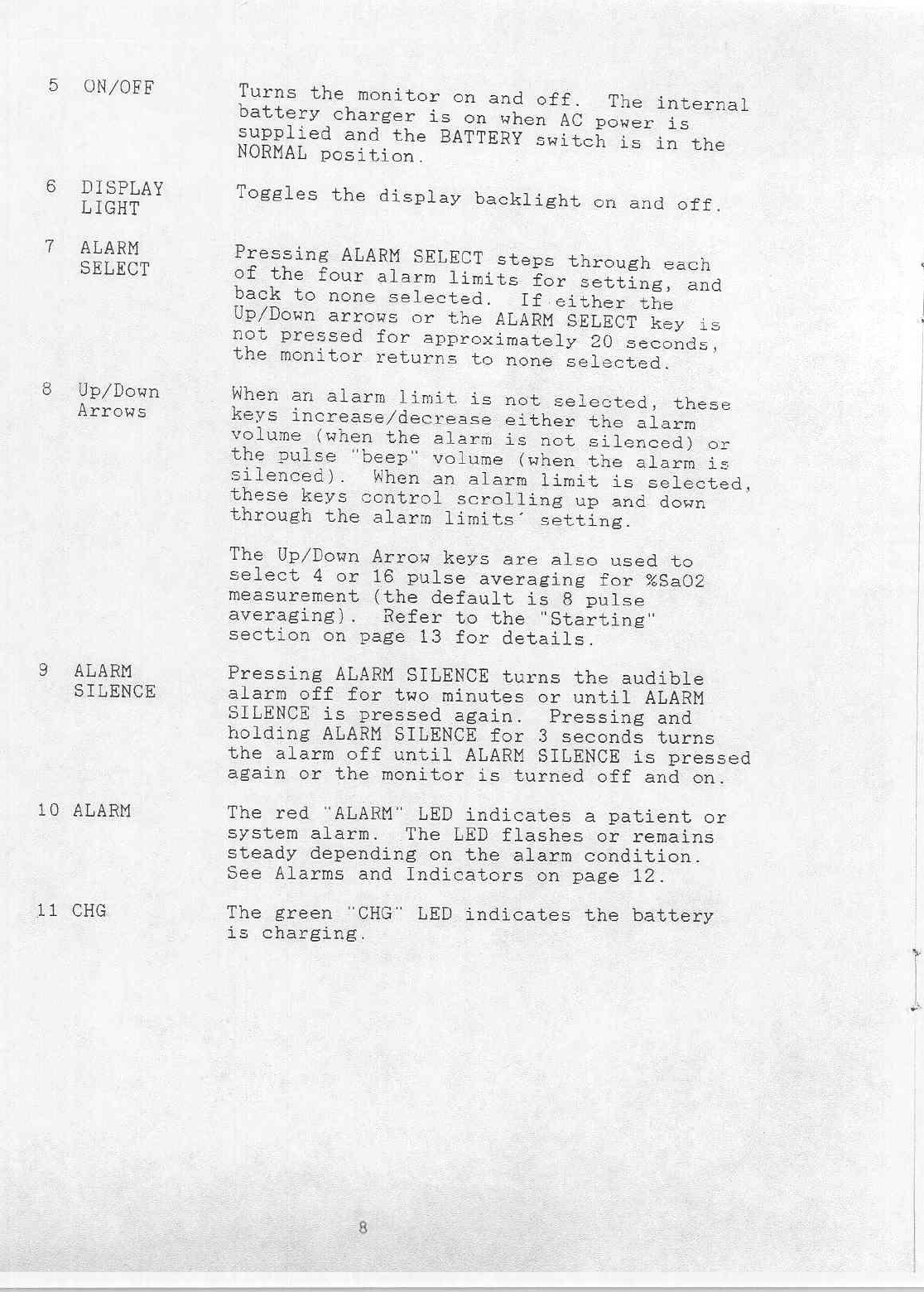
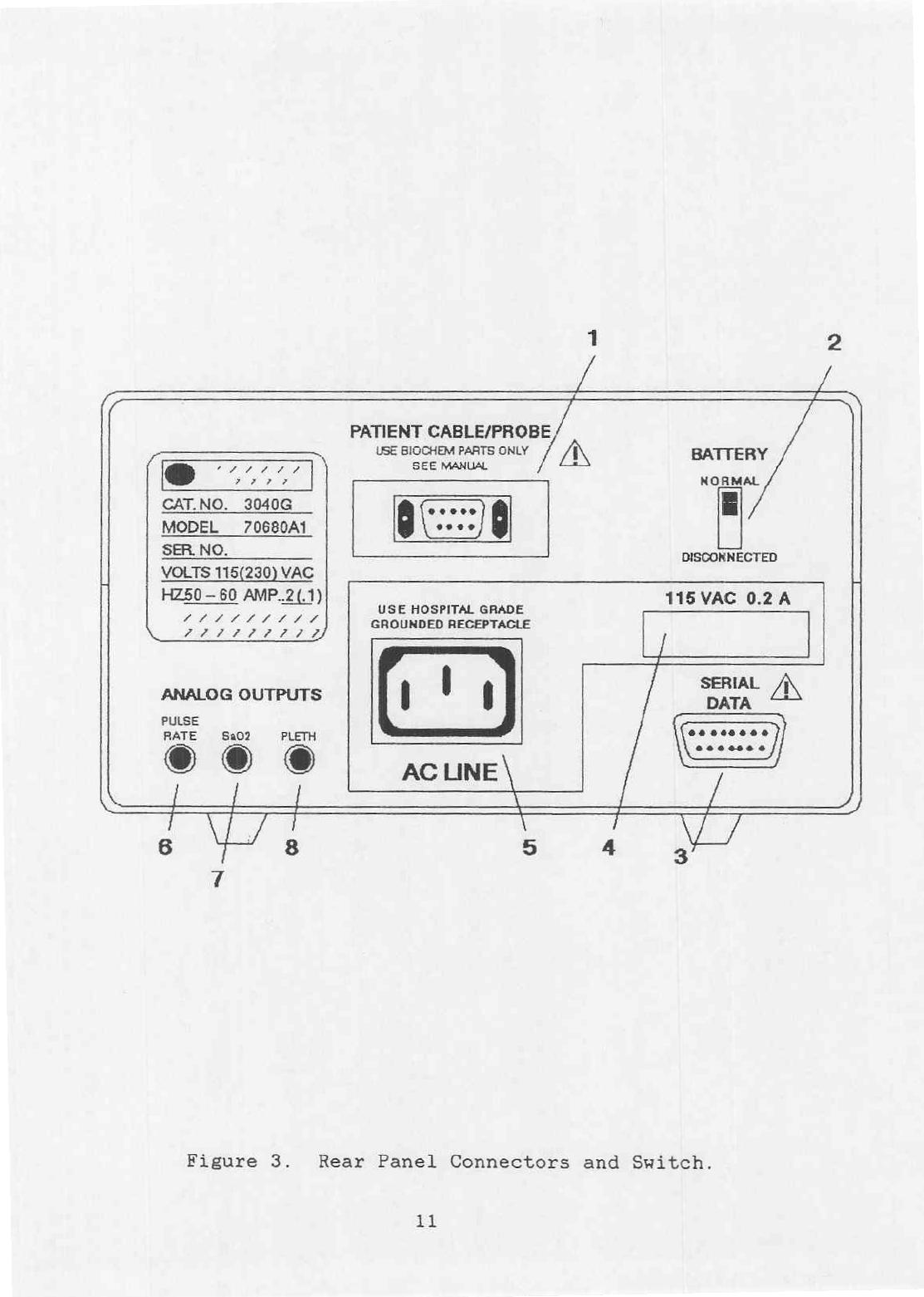
Rear
Panel
Connectors
and
Switch
Refer
to
Figure
3.
Label
Description
1
PATIENT
The
Patient
Cable
is
typically
plugged
into
CABLE/PROBE
this
connector.
The
Finger
and
Universal
“Y"
adapter
probes
may
be
directly
plugged
into
this
connector
if
the
additional
length
of
the
patient
cable
is
not
required.
2
BATTERY
The
BATTERY
switch
is
set
to
NORMAL
for
operation
and
DISCONNECTED
for
shipping
and
long-term
storage.
The
battery
is
charging
when
the
green
“CHG”
LED
on
the
front
panel
is
Lit.
3
SERIAL
DATA
The
3040G
Oximeter
is
interfaced
to
the
optional
3045
microSpan
"Smart"
printer
through
this
connector.
The
3040G
Oximeter
can
be
interfaced
to
any
computer
that
supports
the
3040G
communication
protocol
and
whose
serial
input
port
responds
to
0-5
V
levels.
3040G
communication
protocol
information
is in
the
microSpan
3040G
Oximeter
Service
Manual.
4
VAC
This
is
the
AC
line
voltage
input
setting
RATING
and
current
rating.
Verify
that
the
3040G
Oximeter
is
set
to
the
proper
AC
line
voltage setting
for
your
installation.
If
the
AC
line
voltage
setting
is
incorrect,
do
not
use the
3040G
Oximeter.
Contact
an
authorized
service
center.
5
AC
LINE
The
AC
Power
Cord
is
plugged
into
this
connector.
6
PULSE
RATE
The
PULSE
RATE from
0-250
beats/minute
is
represented
as
0.00
VDC
to
2.50
VDC.
7
Sa02
The
Sa02
level
from
0
to
100%
is
represented
as
0.00
VDC
to
1.00
VDC.
8
PLETH.
The
PLETH.
(plethysmogram)
is
represented
as
0.00
V
to
2.55
V
centered
at
1.28
V.
10
/
/
E
PATIENT
CABLE/PROBE
USE
BIOCHEM
PARTS
ONLY
/
企
BATTERY
db
RC
ERA
ESA
gr
NORMAL
CAT.NO.
3040G
MODEL
7068041
E
SER
NO.
DISCONNECTED
VOLTS
115(230)
VAC
HZ50-
60
AMP..2(.1)
115
VAC
0.2
A
USE
HOSPITAL
GRADE
LLL
AH
PF
GROUNDED
RECEPTACLE
クア
クア
クノ
/
SERIAL
/N
ANALOG
OUTPUTS
DATA
PULSE
RATE
$202
PLETH
©
E
RH
AC
LINE
\
7
Wi
VT
Figure
3.
Rear
Panel
Connectors
and
Switch.
11

Alarms
and
Indicators
Pulse
Beat
Detect
Matched
or
Exceeded
Alarm
Limit
Low
Pulse
Amplitude
Drop
in
Sa02
A
short
"beep"
sounds
each
time
a
pulse
beat
is
detected.
The
volume
is
adjustable
(including
off)
independently
from
the
alarm
volume.
A
two-tone
alarm
sounds
(when
the
alarm
is
not
silenced),
the red
“ALARM”
LED
flashes,
and
the
triangular
indicator
for the
violated
alarm
limit
flashes.
LOW
PULSE
is
displayed.
A
lower-tone
double
"beep"
sounds.
System
Alarms
and
Indicators
Probe
Off
Patient
or
not
Connected
to
Monitor
Searching
too
long
for
Pulse
Low
Battery
Voltage
Battery
Charging
A
double
"beep"
sounds
every
second
(when
the
alarm
is
not
silenced),
CHECK
SENSOR
is
displayed,
and
the
red
“ALARM”
LED
lights
continuously.
A
double
"beep"
sounds
every
second
(when
the
alarm
is
not
silenced),
PULSE
SEARCH
is
displayed,
and
the
red
"ALARM"
LED
lights
continuously.
A
short
burst
of
"beeps"
sounds
when
a
low
battery
voltage
condition
is
first
detected.
LOW
BATT
is
displayed
continuously.
The
green
"CHG"
LED
is
lit.
12
Set
the
BATTERY
switch
(on
the
rear
of
the
monitor)
to
NORMAL.
If
AC
power
is
available,
connect
the
AC
Power
cord
to
the
AC
LINE
connector
on
the
3040G
Oximeter
and
then
to
a
hospital
grade
outlet.
Connect
the
patient
cable
to
the
PATIENT
CABLE/PROBE
connector
on
the
rear
of
the
3040G
Oximeter.
Refer
to
Figures
4-9
and
choose
either
the
Finger
Probe
or
the
Universal
"Y"
Probe
for use
based
on
application
requirements.
Connect
the
probe
to
the
Patient
Cable.
Caution:
Use
only
Biochem
Finger
Probe,
Catalog
No.
3044
or
Universal
"Y"
Probe,
Catalog
No.
3043,
with
the
microSpan
3040G
Oximeter.
Starting
Press
the
front
panel
On/Off
key.
The
3040G
Oximeter
performs
a
self-test,
lights
all
display
legends,
and
displays
the
software
revision.
The
3040G
Oximeter
then
enters
the
monitoring
mode.
The
3040G
Oximeter
defaults
to
an
eight
(8)
pulse
averaging
mode
for
Sa02
measurement,
but
four
(4)
or
sixteen
(16)
pulse
averaging
is
available.
To
put
the
monitor
in
the
4
pulse
averaging
mode,
press
and
hold
the
DOWN
arrow
key
while
turning
the
monitor
on.
The
number
4
appears
for
a
moment
in
the
Sa02
portion
of
the
LCD
display.
To
put
the
monitor
in
the
16
pulse
averaging
mode,
press
and
hold
the
UP
arrow
key
while
turning
the
monitor
on.
The
number
16
appears
for
a
moment
in
the
Sa02
portion
of
the
LCD
display.
To
return
the
monitor
to
the
8
pulse
averaging
mode,
turn
the
monitor
off and
on.
The
3040G
Oximeter
uses
an
8
second
pulse
rate
average
in
the
4
or
8
pulse
Sa02
averaging
mode
and
a
16
second
pulse
rate
average
in
the
16
pulse
Sa02
averaging
mode.
Attaching
the
Sensor
Both
the
Finger
Probe
and
the
Universal
"Y"
Probes
are
reuseable.
See
the
"User's
Maintenance"
section
on
page
17
for
probe
cleaning
instructions.
13

Finger
Probe
Attach
the
probe
to
the
finger
as
shown
in
Figure
4
so
the
cable
protrudes
along
the
palm
of
the
hand.
Very
long
finger
nails
may
make
positioning
of
the
probe
difficult,
resulting
in
a
poor
pulse
signal.
Use
the
Universal
"Y"
Probe,
as
shown
in
Figure
6,
for
patients
with
very long
finger
nails.
Universal
"Y"
Probe:
Attach
the
probe
to
the
patient
as
shown
in
Figures
5,
6, 8,
or
9,
using
adhesive
strips
as
necessary.
When
using
the
Universal
“Y"
Probe
on
the
finger,
attach
the
LED
(light
source)
portion
of
the
sensor
to
the
finger
nail
side
of
the
finger.
Ear
Probe
Attachment:
The
Universal
"Y“
Probe
can
be
adapted
for
use
as
an
ear
probe
with
the
Ear
Clip.
The
Universal
"Y"
Probe
is
attached
to
the
Ear
Clip
as
shown
in
Figure
7.
The Ear
Clip
is
then
attached
to
the
patient's
ear
lobe
as
shown
in
Figure
5.
Verifying
the
Sensor
Placement
Once
the
probe
is
attached
to
the
patient,
allow
several
pulse beats
for
the
monitor
to
stabilize.
Observe
the
pulse
bar
graph
located
on
the LCD
Display.
If
the
pulse
signal
strength
is
low,
the
probe
position
may
need
adjustment.
Measuring
the
Pulse
Rate
and
Sa02
After
approximately
four
or
five
pulse beats,
the
Pulse
Rate
and
Sa02
values
are
displayed.
The
pulse
“beep”
sounds
with
each
pulse
beat
when
the
pulse
tone
is
enabled.
A
lower-tone
double
"beep"
sounds
when
a
drop
in
Sa02
is
detected.
Setting
the
Alarms
Alarms
are
still
active
while
setting,
but
the
"H"
and
"L"
triangular
indicators
do
not
flash
for
violated
alarms.
The
“H"
and
"L"
trianglular
indicators
act
as
a
cursor
to
identify
the
limit
selected
for
adjustment.
Press
the
ALARM
SELECT
key
until
the
cursor
is
positioned
at
the
alarm
parameter
you
are
setting
(High
Sa02,
Low
Sa02,
High
Pulse
Rate,
Low
Pulse
Rate).
Press
the
Up/Down
arrow
keys
to
increase
or
decrease
the
selected
alarm
value.
"--"
in
the
alarm
display
indicates
the
alarm
parameter
is
set
to
OFF.
Note:
The
alarms
in
the
3040G
Oximeter
are
non-overlapping.
You
cannot
set
the
low
alarm
higher
than
the
high
alarm
or
the
high
alarm
lower
than
the
low
alarm.
14
Interpreting
the
Patient
Alarms
When
an
alarm
limit
is
violated,
a
two-tone
alarm
sounds
(when
the
alarm
is
not
silenced),
the
red
"ALARM"
LED
flashes,
and
the
triangular
indicator
for
the
violated
alarm
limit
flashes.
The
alarms
stop
when
the
alarm
limit
is
no
longer
violated.
Press
the
ALARM
SILENCE
key
to
silence
the
alarm
for two
(2)
minutes.
ALARM
SILENCED
flashes
on
the
display.
Press
the
ALARM
SILENCE
key
again
to
end
the
two
minute
alarm
silence.
Press
and
hold
the
ALARM
SILENCE
key
for
three
(3)
seconds
to
silence
the
alarm
indefinitely.
ALARM
SILENCED
is
displayed
continuously.
Press
the
ALARM
SILENCE
key
again
to
end
the
indefinite
alarm
silence
mode.
LOW
PULSE
is
displayed
when
the
pulse
amplitude
is
low.
A
lower-tone
double
"beep"
sounds
when
a
drop
in
9802
is
detected.
Adjusting
the
Audio
Volume
Alarms:
Use the
Up/Down
arrow
keys
to
adjust
the
audio
alarm
volume
(when
not
setting
the
alarm
limits
and
the
alarm
is
not
silenced).
Pulse
"Beep":
Silence
the
audio
alarms
by
pressing
the
ALARM
SILENCE
key
(be
sure
ALARM
SILENCED
is
displayed).
Now
use
the
Up/Down
arrow
keys
to
set
the
pulse
"beep"
volume
(when
not
setting
the
alarm
limits).
BEEP
SILENCED
is
momentarily
displayed
when
the
pulse
"beep"
volume
reaches
off.
Stopping
Press
the
front
panel
On/Off
key
to
turn
the
monitor
off.
If
the
green
"CHG"
LED
is
lit,
the
battery
charging
circuit
is
recharging
the
battery.
15
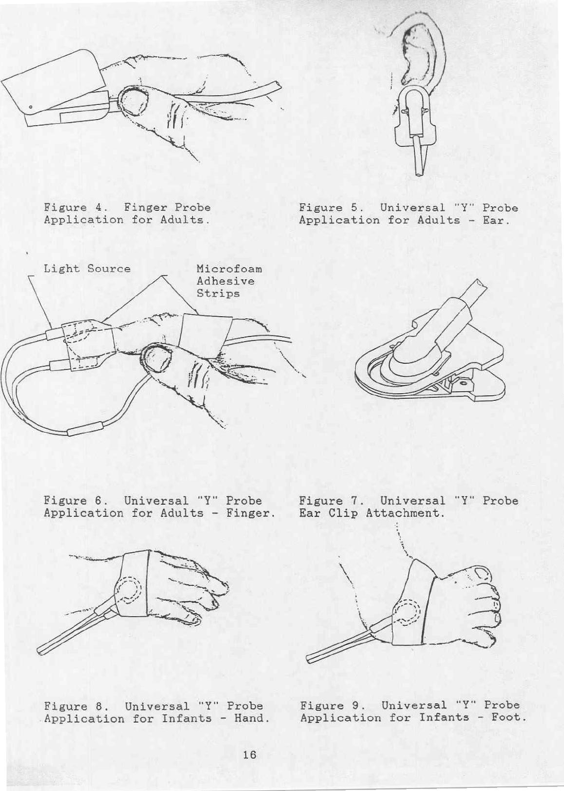
Figure
4.
Finger
Probe
Figure
5.
Universal
"Y"
Probe
Application
for
Adults.
Application
for
Adults
-
Ear.
Light
Source
Microfoam
Adhesive
Figure
6.
Universal
"Y"
Probe
Figure
7.
Universal
"Y"
Probe
Application
for
Adults
-
Finger.
Ear
Clip
Attachment.
Figure
8.
Universal
"Y"
Probe
Figure
9.
Universal
"Y"
Probe
Application
for
Infants
-
Hand.
Application
for
Infants
-
Foot.
16

User’s
Maintenance
The
microSpan
3040G
Oximeter
and
probes
do
not
require
routine
maintenance
other
than
charging
the
battery.
The
battery
should
be
charged
after
the
3040G
is
used
under
battery
operation,
when
the
BATT
LOW
message
is
displayed
on
the
LCD,
or
after
long
term
storage.
If
the
3040G
Oximeter
requires
service,
see
the
"Servicing
the
Monitor"
section
on
page
18.
Cleaning
and
Disinfecting
CAUTION:
Do
not
immerse
the
3040G
Oximeter
or
probes
in
liquid.
Do
not
autoclave
or
ethylene
oxide
sterilize
the
3040G
Oximeter
or
probes.
Unplug
the
AC
power
cord
before
cleaning
or
disinfecting
the
3040G
Oximeter
or
probes.
Clean
the
surfaces
of
the
microSpan
3040G
Oximeter
and
probes
with
a
soft
cloth
moistened
in
a
mild
soap
solution.
If
disinfection
is
required,
wipe
the
surfaces
with
isopropyl
alcohol
or
glutaraldehyde.
Charging
the
Battery
Connect
the
AC
Power
Cord
to
the
AC
LINE
connector
on
the
3040G
Oximeter
and
then
to
a
hospital
grade
outlet.
Set
the
BATTERY
switch
(on
the
rear
of
the
3040G
Oximeter)
to
NORMAL.
Verify
the
green
“CHG"
LED
is
lit.
Ten
hours
of
charging
(with
the
monitor
OFF)
fully
charges
the
battery.
A
fully
charged battery
generally
provides
4
hours
of
operation
(5
hours
with
the
backlight
OFF).
Long
Term
Storage
Storage
Facility
Indoor
Temperature
50-105
degrees
F
Relative Humidity
10-90%
Preservation
Storage
Temp.
Charging
interval
65
degrees
F
every
12
months
85
degrees
F
every
6
months
105
degrees
F
every
3
months
Periodic
Inspection
None
required.
Special
Procedures
Set the
rear
panel
BATTERY
switch
to
the
DISCONNECTED
position.
Store
the
3040G
Oximeter
and
accessories
in
the
original
packing
materials
and
shipping
carton.
17
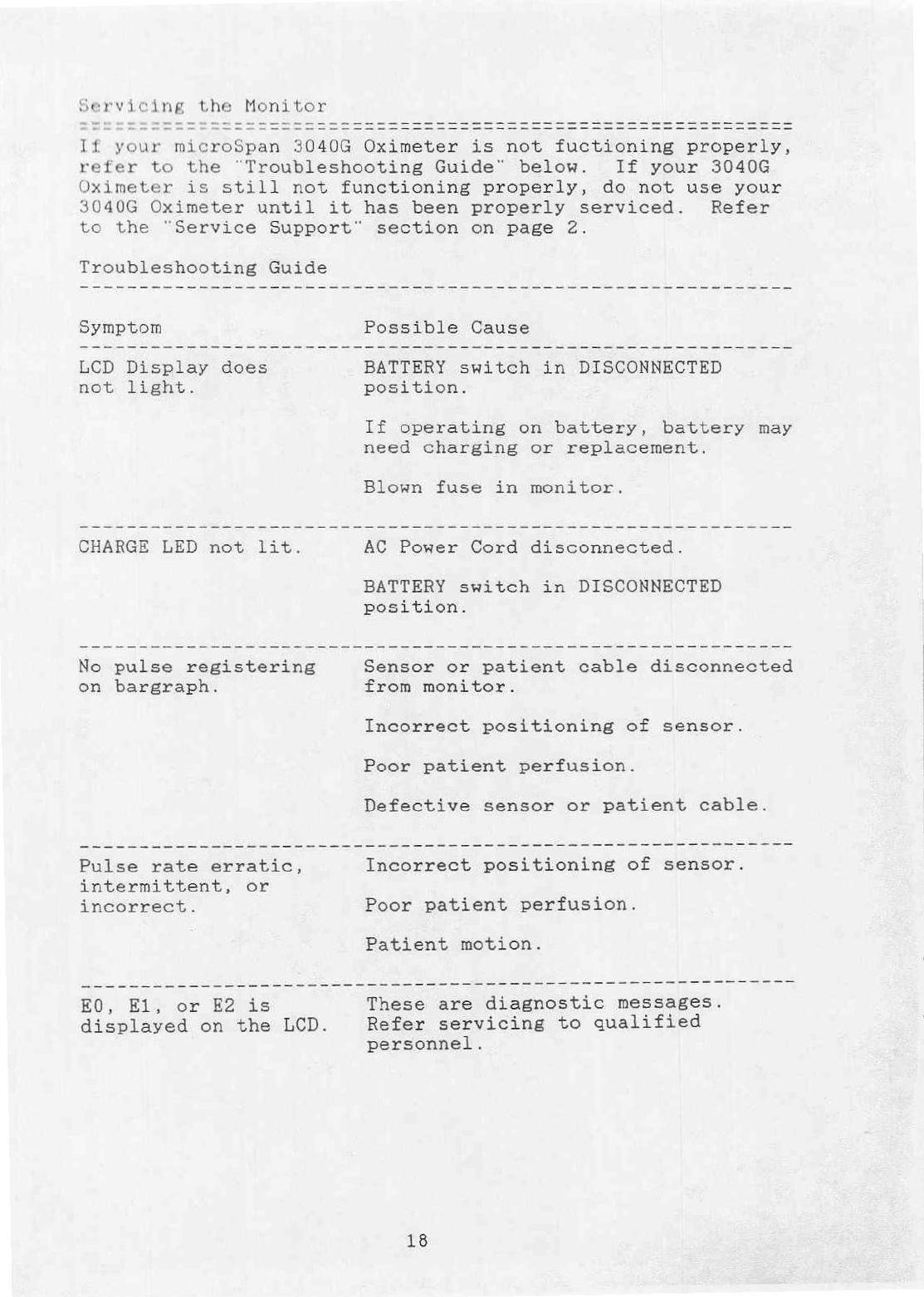
If
your
not
fuctioning
properly,
refer
to
the
"Troubleshooting
Guide"
below.
If
your
3040G
Oximeter
is
still
not
functioning
properly,
do
not
use
your
3040G
Oximeter
until
it
has
been
properly
serviced.
Refer
to
the
"Service Support"
section
on
page
2.
Troubleshooting
Guide
LCD
Display
does
not
light.
No
pulse
registering
on
bargraph.
Pulse
rate
erratic,
intermittent,
or
incorrect.
E0,
El,
or
E2
is
displayed
on
the
LCD.
BATTERY
switch
in
DISCONNECTED
position.
If
operating
on
battery,
battery
may
need
charging
or
replacement.
Blown
fuse
in
monitor.
AC
Power
Cord
disconnected.
BATTERY
switch
in
DISCONNECTED
position.
Sensor
or
patient
cable
disconnected
from
monitor.
Incorrect
positioning
of
sensor.
Poor
patient
perfusion.
Defective
sensor
or
patient
cable.
Incorrect
positioning
of
sensor.
Poor
patient
perfusion.
Patient
motion.
These
are
diagnostic
messages.
Refer
servicing
to
qualified
personnel.
18
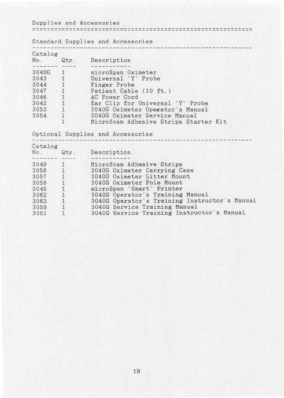
Supplies
and
Accessories
microSpan
Oximeter
Universal
"Y"
Probe
Finger
Probe
Patient
Cable
(10
ft.)
AC
Power
Cord
Ear
Clip
for
Universal
"Y"
Probe
3040G
Oximeter
Operator’s
Manual
3040G
Oximeter
Service
Manual
Microfoam
Adhesive
Strips
Starter
Kit
Optional
Supplies
and
Accessories
No.
Microfoam
Adhesive
Strips
3040G
Oximeter
Carrying
Case
3040G
Oximeter
Litter
Mount
3040G
Oximeter
Pole
Mount
microSpan
"Smart"
Printer
3040G
Operator’s
Training
Manual
3040G
Operator’s
Training
Instructor’s
Manual
3040G
Service
Training
Manual
3040G
Service
Training
Instructor’s
Manual
19
Table of contents
Popular Medical Equipment manuals by other brands


dispomed
dispomed Moduflex Access 2 manual

Kyoto Kagaku
Kyoto Kagaku NCPR Simulator instruction manual

Babytone
Babytone PO5 user manual

Benchmark Scientific
Benchmark Scientific Accuris Instruments MyGel InstaView operating manual

Thuli Tables
Thuli Tables 500 Stationary owner's manual

DR-HO'S
DR-HO'S MotionCiser user manual