Bioclimatic VIROXX E150++ User manual
air purifier
VIROXX E150++
instruction manual
version: 1.4
state: January 2019

2
manufacture and sales:
bioclimatic GmbH
Im Niedernfeld 4
31542 Bad Nenndorf
Germany
phone: ++49 - 57 23 - 94 40 - 0
fax: ++49 - 57 23 - 94 40 - 30
e-mail: info@bioclimatic.de
URL: www.bioclimatic.de
In case of any questions according to operation or maintenance of the
VIROXX E150++ please indicate the following information’s:
–unit model
–unit number.
You will find the unit model and number on the type designation plate at the
frontside of the unit.
©Copyright 01/2019.
Reproduction and copy, also in extracts, are only permitted for internal use.
The manufacturer of the VIROXX E150++ reserves all further rights.
Version 1.4 (January 2019)

3
Index
1device description of the VIROXX E150++ 5
1.1 purpose of use 5
2safety instructions 7
3Technical Data 8
4Safety instructions 9
5operation 10
5.1 switch-on and off 10
5.2 the control panel 10
5.3 decommissioning of VIROXX E150++ 11
5.4 recommissioning of VIROXX E150++ 11
6function control 12
7maintenance 13
7.1 cleaning and maintenance 13
7.1.1 maintenance schedule 13
7.1.2 cleaning 14
7.2 opening of the VIROXX E150++ 14
7.3 control and exchange of the catalyst 15
7.4 control and exchange of the ionization tubes 16
7.5 control and exchange of the UV-lamp 17
7.6 control and exchange of the prefilter 18
7.7 exchange of the fuse 18
8malfunctions and trouble shooting 19
8.1 list of malfunctions 19
8.2 disposal 19
9scope of delivery 20
9.1 standard scope of delivery 20
9.2 spare parts 20
10 technical specifications 21
11 declaration of the manufacturer 21
12 guarantee bond 22
13 EC Declaration of Conformity 23

4
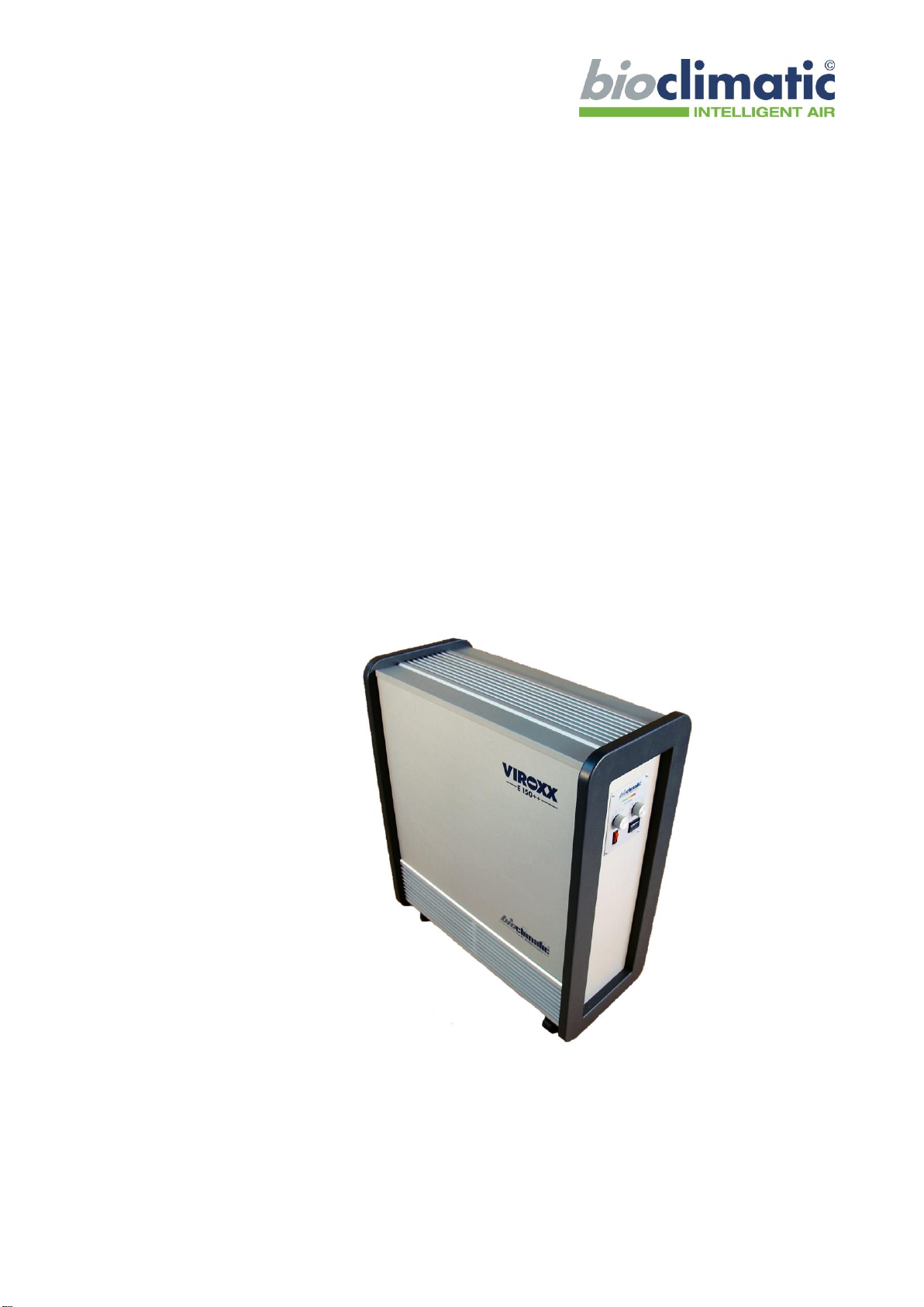
overview
front side
back side
1 castor
2 air inlet
5 power supply
and fuse
3 control panel
4 air outlet
6 maintenance
door
5
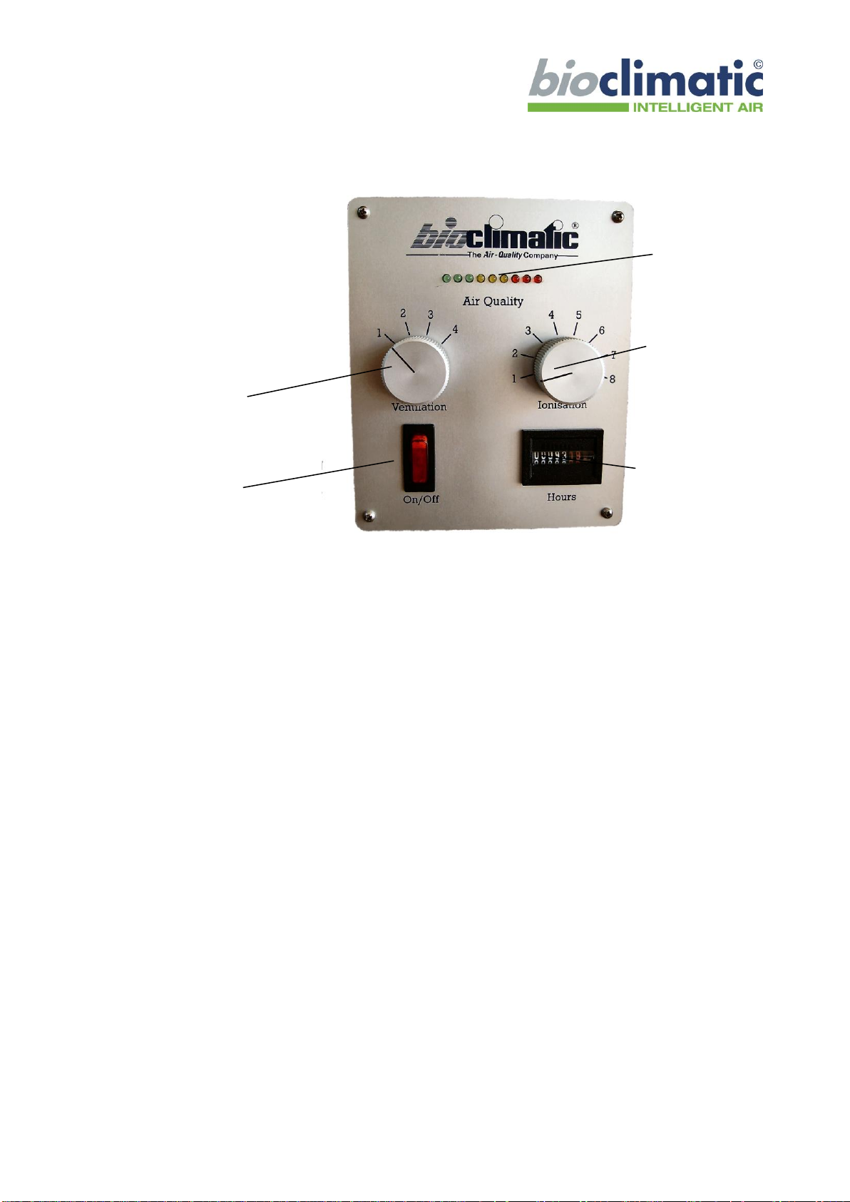
control panel
1device description of the VIROXX E150++
1.1 purpose of use
The VIROXX E150++ air purifier inactivates germs like viruses, bacte-
ria’s, moulds and yeasts and abates airborne pollutants and particles as well
as odours of the indoor air.
The combination of prefiltration, photochemical disinfection, catalytical
oxidation, high performance micro filtration and bipolar ionization purifies
the indoor air.
The air purification level of the VIROXX E150++ is adjustable to the real
air indoor contamination level. By use of an Air Quality Detector The mobile
and self-contained VIROXX E150++ can be installed in any kind of places.
8 power switch
7 fan regulator
9 operation
time meter
10 ionization
regulator
11 air quality
level
6
1.2 functional description
These chapter describes the main technical basics of the working function of
VIROXX E150++.
The patented VIROXX-Technology guarantees that, dangerous airborne
contaminants and microorganisms are inactivated and particles are abated
effectively.
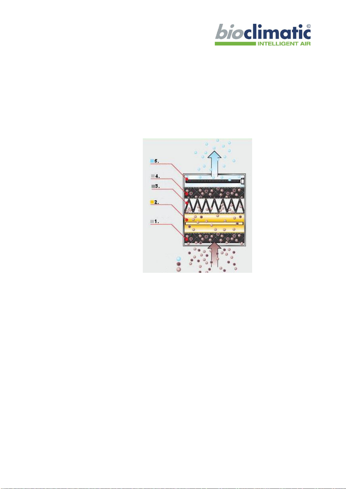
pic. 1: VIROXX working function
1. step: prefiltration
A fine filter, installed at the entrance of the system (2), removes dust
particles from the incoming air.
2. step: photochemical disinfection
The combination of photo-oxidation and photo-catalysis allows the
simultaneous inactivation of micro-organisms and viruses and the
degradation of odour molecules. For achieving high abatement effi-
ciencies, lamps emitting powerful short UVC waves and photo-active
catalysts have been used.
3. step: catalytical oxidation
On the downstream side of the photo-chemical disinfection step, an
extra catalyst is installed in order to improve the abatement efficien-
cy.

7
4. step: high performance micro filter
The high performance micro filter guarantees the effective abate-
ment of airborne particles.
5. step: bipolar ionisation
This last air treatment step charges the disinfected air with healthy
air ions before its release in the ambiance. High concentrations of air
ions are not only healthy for humans but also abate micro-organisms
and viruses in the air and on surfaces and neutralize unpleasant
odours.
sensor supported regulation
The integrated Air Quality Detector adjusts the intensity of air purifica-
tion automatically to the real air contamination level.
2safety instructions
For your own safety and regarding please note the following advices:
-Please study this instruction manual carefully. It’s a part of the
VIROXX E150++ and must be available every time.
-Use the VIROXX E150++ only for the described applications.
-The supply voltage of the unit and on site must correspond to each
other.
-The VIROXX E150++ sucks ambient air during operation. There-
fore do not cover the unit during operation.
-Please don’t use VIROXX E150++ in damp locations or outdoor.
-Please use the VIROXX E150++ only with products recommend in
this manual. Bioclimatic can not guarantee a malfunction free opera-
tion of the unit by using other products with the unit.
-The claims of guarantee and liability expire by using not recommend
or original products/spare parts with the
VIROXX E150++.
Do not throw or push the unit and don’t positioning it close to heat sources
or isolation directly.
bioclimatic assumes no guarantee for damage, which results from neglect of
this manual or from not intended use of the unit.

8
3Technical Data
Room volume
ca. 150 m³
Dimensions
ca. 710/335/815 mm (W x H x D)
weight
ca. 45 kg
Ambient temperature
operation
storage
+5 to + 40 °C
0 to + 50 °C
relative humidity
max. 85 %
Power supply
230 V AC / 50Hz
Power consumption (max.)
ca. 240 W
Air flow volume (max.)
ca. 250 m³/h
UV-lamp
1 x 430/A (ozone free)
Ionisation tube
2 x IRF
fuse
1.6 A (slow blow)
Radio shielding
EMC
DIN EN 55011
EN/IEC 61000-4-3
Degree of Protection
IP44*
* only electrical components with installed tube socket seal
Tab.
1:
Technical Data VIROXX E150++
9
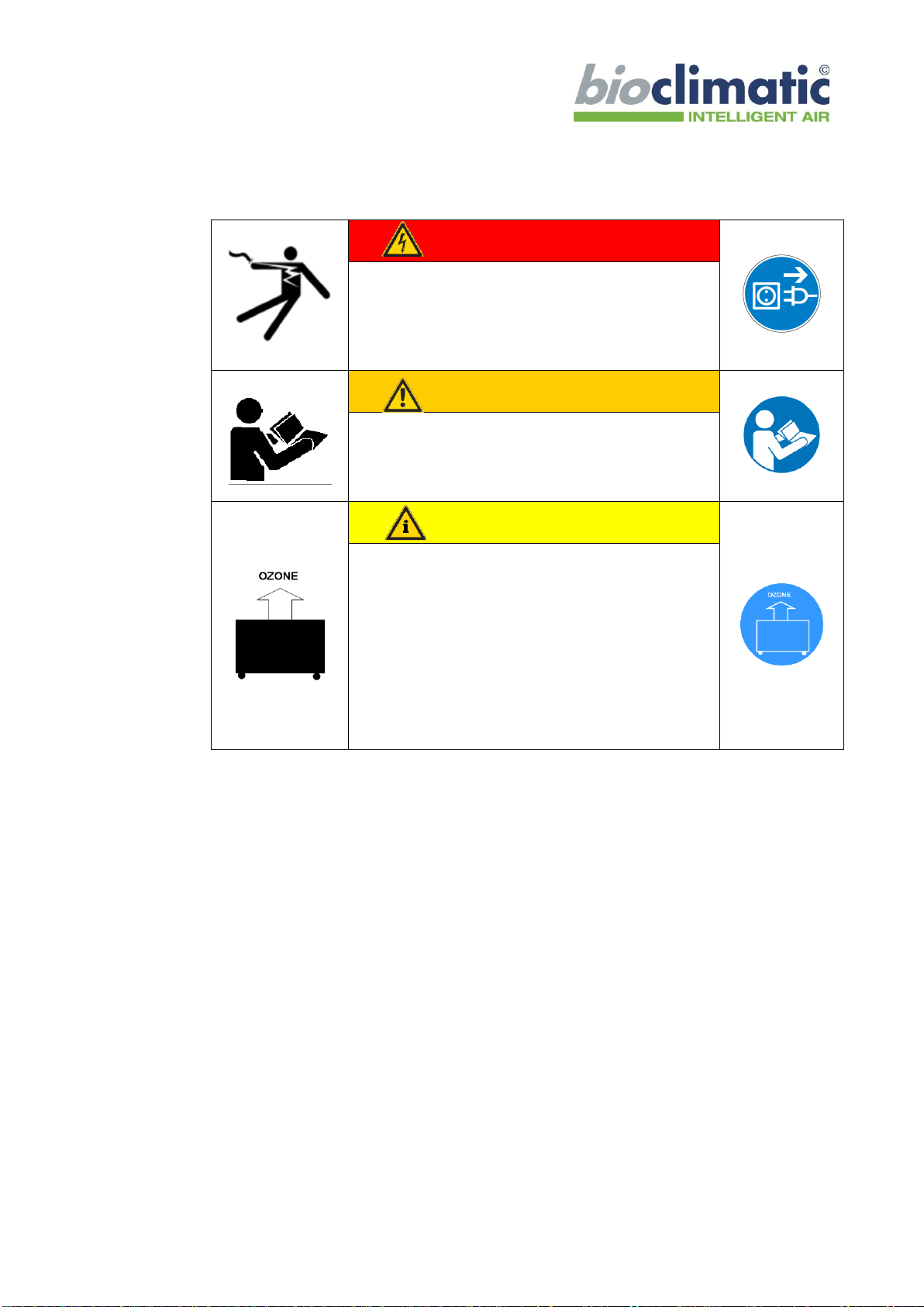
4Safety instructions
Caution, high voltage!
Electrical danger!
Unplug the mains plug before working on the
unit or moving it. Respectively all poles of the
the device must be disconnected from the
mains!
Warning
Only qualified staff may work on the device!
All works concerning mounting, start-up and
maintenance must be carried out by qualified
staff only.
Caution
Take the ozone concentration in the room into
account!
Take the dimensioning specifications into
account, as the device produces ozone during
operation.
If the dimensioning table is taken into account
and the device is set in accordance with the
User Manual, the ozone produced will not
exceed the maximum admissible concentration.

10
5operation
5.1 switch-on and off
The operation panel (3) of the VIROXX E150++ is located on the side of
the unit.
In order to put the VIROXX E150++ into operation press the power
switch (8).
-The orange power control lamp (8) shines continuously.
-The unit is now in operation and works continuously.
-The flow rate of the VIROXX E150++ could be adjusted in 4 steps
by use of the fan regulator (7).
-The output of activated oxygen could be adjusted in 8 steps by use of
the ionization regulator (10).
5.2 the control panel
pic. 2: control panel of the VIROXX E150++
power switch (8):
-by use of the power switch the unit gets in operation
-the red power control lamp (8) shines continuously.
-in case of a malfunction the power control lamp don’t shines (see list
of malfunctions 6.1). Please contact your specialist dealer.
8 power switch
7 fan regulator
9 operation
time meter
10 ionization
regulator
11 air quality
level

11
fan regulator (7):
-The flow rate of the unit could be adjusted in 4 steps by use of the fan
regulator (7).
ionization regulator (10):
-The output of activated oxygen could be adjusted in 8 steps by use of
the ionization regulator (10). The sensor will regulate the ionisation
from step “1” up to the chosen step.
-This is an push / pull switch! If it is pulled out, the sensor is not in
function. The ionisation works always according to the chosen step.
operation time meter (9):
For control of the service intervals; display in hours and minutes,
the maximum display is 99,999.99 h.
Air Quality Level(11):
For indication of air quality level in 9 Steps.
5.3 decommissioning of VIROXX E150++
If you don’t want to use the unit for longer time, cover the unit to protect it
for contamination with dust and store it at a dry place.
5.4 recommissioning of VIROXX E150++
Check if the air inlet and outlet is free of impurities. Please clean the unit
from dust agglomerations with a brush.

12
6function control
The maintenance and function control jobs need to be done by
qualified personnel only!
4.000 hours of operation after commissioning, after every mainte-
nance and quarterly check the function of the unit.
1. Press the power switch (7) to turn on the VIROXX E150++
-The red power control lamp (7) is shining.
-The ventilator and the UV-lamp are in operation.
2. Check the flow rate of the ventilator by using the fan regulator
switch (7). Switch up to step 4, the flow rate increases.
3. Check if the characteristic crackle of the ionization tubes could be
heard at the air outlet of the unit. By increasing of the ionization in-
tensity (9) the crackle sound increases.
4. Check the display of the operation time meter (4) if it‘s count up af-
ter one minute of operation.
If the unit doesn’t work properly, please contact your specialist dealer.

13
7maintenance
7.1 cleaning and maintenance
The maintenance jobs need to be done by qualified personnel of your
specialist dealer only.
For every maintenance job pull the plug. Caution, in case the unit is not
separated from power and still switched on, there is a high
voltage charge (up to 3,0 kV) at the ionization tube.
7.1.1 maintenance schedule
service interval
maintenance descrip-
tion in chapters
function control
after the first 2.000
operation hours
then quarterly
4
control of the UV-
lamp *
after the first 2.000
operation hours
then quarterly
contact specialist dealer
exchange of the UV-
lamp *
after 8.000
operation hours or
after 1½ years
contact specialist dealer
control of the
ionization tube
after the first 2.000
operation hours
then quarterly
contact specialist dealer
exchange of the
ionization tube *
after 16.000
operation hours or
after 3 years
contact specialist dealer
control of the
prefilter *
after the first 2.000
operation hours
then quarterly
contact specialist dealer
exchange of the
prefilter
after 3 to 6 month
contact specialist dealer
control of the
catalyst *
after the first 2.000
operation hours
then quarterly
contact specialist dealer
exchange of the
catalyst
after 3 to 6 month
contact specialist dealer
14
service interval
maintenance descrip-
tion in chapters
control of the high
performance micro
filter *
after the first 2.000
operation hours
then quarterly
contact specialist dealer
exchange of the high
performance micro
filter
after 3 to 6 months
contact specialist dealer
* Spare parts could be purchased and disposed by bioclimatic respec-
tively.
7.1.2 cleaning
Clean the unit from time to time with a damp cloth.
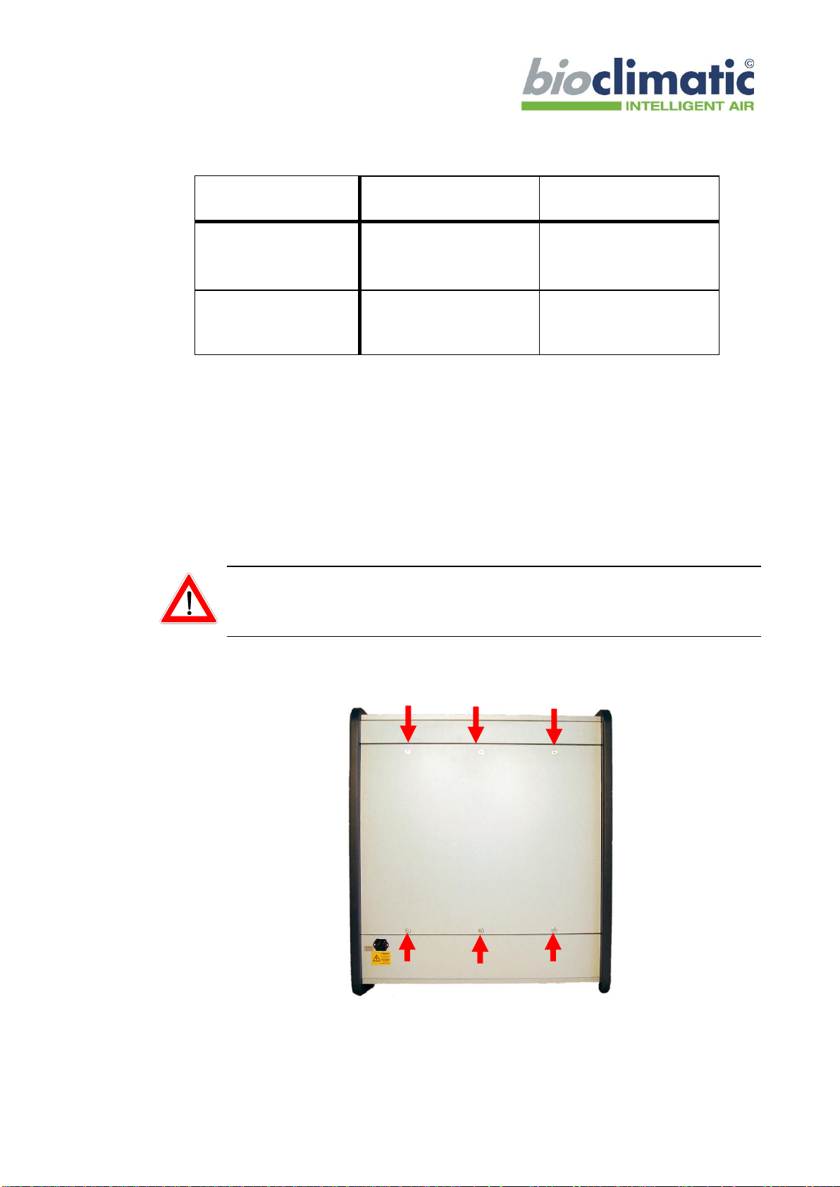
7.2 opening of the VIROXX E150++
For every maintenance job pull the plug. Caution, in case the unit is not
separated from power and still switched on, there is a high voltage
charge (up to 3 kV) at the ionization tubes.
To open VIROXX E150++ for maintenance jobs remove the six screws at
the back side of the unit (see pic. 3.2.1).
pic. 3.2.1
Afterwards remove the maintenance door carefully.
Now all compounds of the VIROXX E150++ are reachable.
15
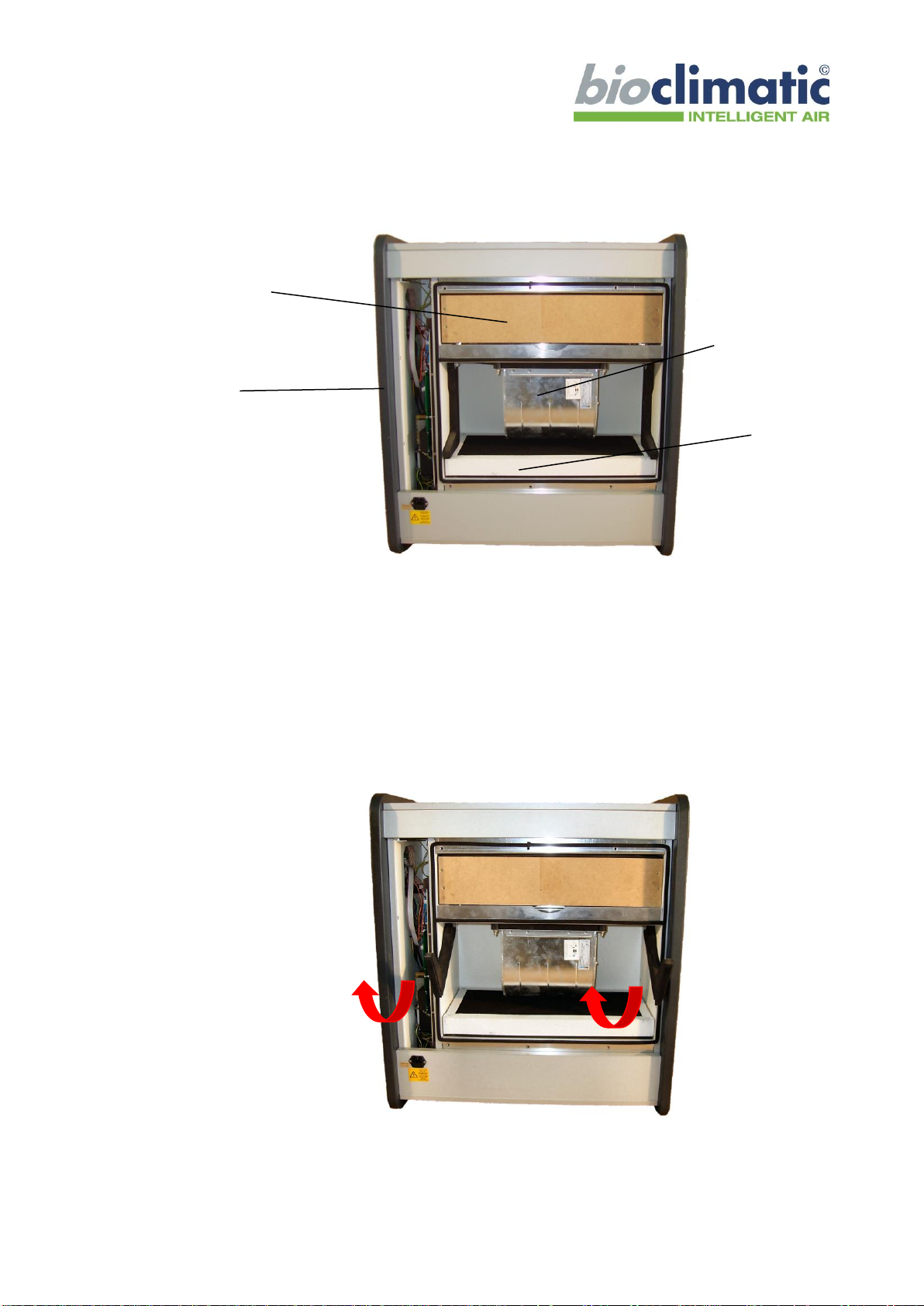
pic. 3.2.2
7.3 control and exchange of the catalyst
To check if the catalyst is damaged or contaminated with impurities please
open the unit (see chapter).
Pull the two levers which fix the catalyst and the high efficiency micro filter
(see. pic. 3.5.1).
pic. 3.2.3
12 micro filter
13 electronic
14 fan
15 catalyst
16
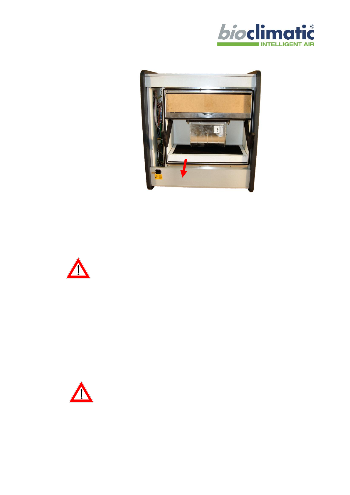
pic. 3.2.4
Now the catalyst can be pulled out (see pic. 3.2.4).
In case of the catalyst is polluted with impurities exchange the catalyst.
By insertion of the catalyst, please take care, that the seal at the rear
side of the catalyst would not be damaged.
Afterwards assemble the unit in reverse order.
7.4 control and exchange of the ionization tubes
Switch on the VIROXX E150++ and adjust with the ionisation regulator
(4) to ionisation level one.
Check if the characteristic crackle could be heard at the air outlet (1).
By increasing of the ionization intensity with the ionization regulator (4)
(the switch has to be pulled out!) the crackle must increase with a delay of
approx. 5 seconds.
Pull the plug.
Caution, in case the unit is not separated from power and still
switched on, there is a high voltage charge (up to 3 kV) at the
tube socket!!!
Open the air outlet.
Check if the ionization tubes are contaminated or damaged.

17
For the cleaning of the ionization tubes, take them from the socket by
turning anti clockwise. During this procedure you need to lift the contact
spring.
For cleaning of the ionization tubes please follow the next steps:
•Remove outer mesh from the tube carefully. If the mesh sticks to the
tube, take them into both hands and move hands in opposite direc-
tion. Once loose, strip the mesh.
•Clean the mesh with antifat detergent, so that the possible fat layer
can be removed completely. Hold the tube into rising warm water for
cleaning.
•Dry well, so no humidity remains in the mash or on the tube.
•Fix again the mesh in a way that the top end of the inner and
outer mesh matches.
•Fix the tubes tight to the socket.
7.5 control and exchange of the UV-lamp
For the function control of the UV-lamp open the VIROXX E150++ at the
backside or remove the grid of the air inlet.
•In a distance of approx. 1.5 –2 m switch on the unit for a short
moment, to check if the UV-lamp is working.
•Pull the plug of the VIROXX E150++ afterwards.
•Remove the UV-lamp
•Check if the UV-lamps are contaminated with impurities.
By dismounting and mounting, as well as by cleaning of the UV-lamps
please touch them only at the ceramics at the end of the UV-lamps (Don’t
touch the glass, also few impurities can decrease the life span!).

18
To clean the UV-lamp use a damp cloth and dry them afterwards sufficient.
Afterwards assemble the UV-lamp in reverse order.
7.6 control and exchange of the prefilter
The prefilter is integrated into the air inlet. Then check the prefilter of
impurities or damages removes the grid of the air inlet.
7.7 exchange of the fuse
You will find the fuse of the VIROXX E150++ in the power supply at the
backside of the unit. The fuse holder can only be opened if the power cord is
removed!
For the exchange of the fuse see the following steps:
1. Disconnect the power cord
2. Open the fuse holder with a screwdriver or similar
3. Change the fuse
4. Push the fuse holder back
5. Connect the power cord

19
8malfunctions and trouble shooting
8.1 list of malfunctions
malfunction
reason
trouble shooting
no ventilator sound, red
power control lamp
turned off
malfunction of fuse
control / change the fuse
no supply voltage
connect the unit to the
supply voltage
line cord damaged
contact specialist dealer
no or very low flow rate
though highest
ventilator level is
switched on
- malfunction of the
ventilator
- micro filter blocked
- catalyst blocked
- prefilter blocked
contact specialist dealer
no or very low abate-
ment of particles
high performance
micro filter blocked or
damaged
contact specialist dealer
no characteristic
crackle of the ioniza-
tion tube could be
heard at the air outlet
malfunction of the
ionization tube
contact specialist dealer
no supply voltage
connect the unit to the
supply voltage
malfunction of fuse
control / change the fuse
8.2 disposal
For the appropriated disposal of the VIROXX E150++ please contact
your specialist dealer of bioclimatic.

20
9scope of delivery
9.1 standard scope of delivery
2 x ionization tube type IRF
1 x UV-lamp type 430/A
1 x catalyst
1 x prefilter
1 x high performance micro filter
1 x instruction manual
9.2 spare parts
The following spare parts could be sourced by bioclimatic.
parts.: spare part name
IRF- ionization tube
UV-lamp
prefilter
high performance micro filter
catalyst
Table of contents
Other Bioclimatic Air Cleaner manuals


Popular Air Cleaner manuals by other brands


Hamilton Beach
Hamilton Beach 4160 Use & care guide

NANO HUB
NANO HUB ESPERO 100 LIFT User and maintenance manual

Fellowes
Fellowes AeraMax Pro AM4 PC quick start guide

lakeair
lakeair CM2-RC2 120 Volt Operating and service manual

Olimpia splendid
Olimpia splendid AURA ABSOLUTE Instructions for use and maintenance

AllerAir
AllerAir Air Filter 5000 EXEC brochure