Bioclimatic MC-880 Series Technical Document

OUR MISSION
To design and build quality engineered air cleaning systems
to provide indoor comfort, protect occupants, and ensure the
reliability of critical systems and processes.
Bioclimatic.com
265-AUG-2021
IMPORTANT
Save this Document
for Future Reference &
Warranty Information
MC-880 System Series
Installation, Operation
and Maintenance Guide

Installation, Operation & Maintenance Guide MC-880 System Series 2
1-800-394-3458 265-AUG-2021 Bioclimatic.com
! I M P O RTA NT!
READ THIS BEFORE STARTING INSTALLATION.
DO NOT THROW AWAY THIS GUIDE.
How to Contact Us: If you need help, please contact a
Bioclimatic Air Systems Representative for technical assistance.
For installation you MUST:
■ Always disconnect power to the unit before handling any of the
components.
■ DO NOT connect to the power before the installation is complete and
personnel are aware of the imminent operation.
■ Carefully read this instruction booklet before beginning the installation.
■ Follow each installation or repair step exactly as shown and explained in
this guide.
■ Observe all local, state, national and international electrical codes.
■ Pay close attention to all warnings and caution notices given in this guide.
!CAUTION!
Do not touch while in operation shut off electricity before servicing!
This equipment should be inspected frequently and collected dirt removed from it regularly to prevent excessive
accumulation that may result in flashover or risk of fire.
!MISE EN GARDE!
Ne touchez pas pendant le fonctionnement couper l’électricité avant l’entretien
Cet équipement doit être inspecté fréquemment et la saleté collectée doit être retirée régulièrement pour éviter
toute accumulation excessive pouvant entraîner un contournement ou un risque d’incendie.

Installation, Operation & Maintenance Guide MC-880 System Series 3
1-800-394-3458 265-AUG-2021 Bioclimatic.com
01 INTRODUCTION 5
1.1 Disclaimer 5
1.2 Receiving 5
1.3 Handling 5
1.4 Storage 6
1.5 Warranty 7
02 INSTALLATION 8
2.1 Unit Location 8
2.2 Unit Installation 8
2.3 Electrical Connections 9
2.4 Filter Installation 9
03 PHYSICAL DESCRIPTION 10
3.1 Principle of Operation 10
3.2 Remote Control 11
3.3 Filter Change Indicator 12
3.4 Prefilter 12
3.5 TA Media 12
3.6 Primary Filter 12
3.7 Bi-polar Ionization 12
04 STARTUP INSPECTION 13
4.1 General 13
4.2 Inspection Check List 13
4.3 Electrical Connection & Power Up 13
Table of Contents

Installation, Operation & Maintenance Guide MC-880 System Series 4
1-800-394-3458 265-AUG-2021 Bioclimatic.com
05 OPERATION & MAINTENANCE 13
5.1 General 13
5.2 Standard Control 14
5.3 Remote Control Option 14
5.4 Multiple Remote Control 14
5.5 Building Management System Control (BMSC) 14
5.6 Filter Change Light Adjustment 15
5.7 Filter Maintenance 15
5.8 Gasket Replacement 16
06 APPENDICES 17
07 PRODUCT NUMBERS 22
Installation, Operation & Maintenance Guide MC-880 System Series 5
1-800-394-3458 265-AUG-2021 Bioclimatic.com
01 INTRODUCTION
1.1 Disclaimer
These instructions are submitted with the implicit understanding that:
1. This manual is to guide the user of Bioclimatic equipment in the proper installation, operation and maintenance procedures to
insure maximum equipment life with efficient operation.
2. The customer has assigned competent maintenance and operating personnel to the system described herein and will assume
operational and maintenance responsibility upon start-up of the system.
3. The customer will read and thoroughly examine the foregoing instructions and will notify the seller of any points not fully
understood, points of conflict or error.
4. The customer, in lieu of any notification to the contrary, has read and fully understands the operation of the system and
is aware of the hazards of corrosion, abrasion and fire or explosion and shall take the necessary steps in the operation of
equipment to control such hazards to the maximum extent possible.
5. Start-up assistance or field engineering service provided by B.A.S. shall in no way relieve the customer of responsibility for the
proper operation of the system.
1.2 Receiving
Products leaving the B.A.S. factory are inspected and in satisfactory operating condition. All equipment should be thoroughly
inspected when received. Although all units are properly packaged, rough handling in transit can cause breakage. Any shortage
or damage should be reported at once to the transportation company. Note the damage on the bill of lading before signing for the
shipment. No equipment may be returned to Bioclimatic without written authorization. Returned equipment sent without
authorization will be refused and returned to sender.
After receiving the MC-880, remove the carton and place the unit in its operating location. Remove the access panel and remove
the ionization tubes and filters. Inspect all parts for damage. If any parts are damaged, contact the shipping company immediately
to file a claim for damaged equipment. Note the damage on the bill of lading before signing for the shipment. All products are
shipped F.O.B. (Ex Works, FCA) Bioclimatic warehouse. Responsibility for all equipment passes to the buyer at the time equipment
is loaded onto the carrier’s truck.
1.3 Handling
Handle equipment with care when removing external packaging or moving equipment to prevent damage to special paints and
surface coating. A small chip in the paint or coating will break the continuity of the surface treatment and destroy its protective
value. Always touch-up scratched surfaces prior to installation and start-up.
IMPORTANT: Any modifications to the unit by unauthorized personnel will void factory warranty.
The unit must be installed in accordance with the manufacturer’s instructions to preserve warranty.
Continue on Next page

Installation, Operation & Maintenance Guide MC-880 System Series 6
1-800-394-3458 265-AUG-2021 Bioclimatic.com
1.4 Storage
When storing equipment, care must be taken to protect bearings, shafts, electrical connections, leads and finished surfaces
from moisture, and contamination. Do not store unit outdoors. Do not store any other material on top of equipment. Periodic
inspections of the equipment should be made until it is ready to be put into service. Remove and seal all filters from equipment
when storing.
Note: If components are not installed upon delivery, it must be stored in a weather-protected area.
Continue on Next page

Installation, Operation & Maintenance Guide MC-880 System Series 7
1-800-394-3458 265-AUG-2021 Bioclimatic.com
1.5 Warranty
The seller warrants the equipment against defective workmanship and material for fifteen (15) months from date of factory
shipment or one (1) year from commissioning, whichever occurs first. In the fulfillment of its warranty, the sole obligation of seller
shall be to repair or replace, at its option, F.O.B. its factory, any part or parts which are returned F.O.B. its factory, shipping charges
prepaid, and which after inspection by seller are found to be defective. Buyer shall notify seller of defect in writing, promptly upon
discovery and within the warranty period. This warranty does not cover defects caused by corrosion or normal deterioration; it
does not extend to consequential damage, loss or delay associated with a warranty defect; and it does not cover any cost of labor,
travel, or other expense associated with the repair or replacement of defective parts. Seller assumes no liability for product loss
or other claims whatsoever arising out of the use or application of the equipment in any operations, whether the machine is used
alone or in conjoint use with other equipment or processes. Notwithstanding the foregoing, seller’s warranty obligations with
respect to any items not manufactured by seller shall not exceed the obligations undertaken by the manufacturer thereof under
express warranty to the seller. This express warranty is in lieu of all other warranties of fitness of the machine for any particular
purpose.
There are no other representations, warranty of condition in any respects either expressed or implied, statutory, or otherwise in
contract or tort, other than what is stated above.
The seller shall not be held liable in any way for consequential damages, however caused.
This warranty will not apply if the seller’s equipment has been damaged due to improper installation, alteration, abuse or misuse,
accident, fire, flood, or unavoidable circumstance. Further, this warranty will not apply if repairs, replacements, or alterations are
made by others without the seller’s prior written authorization.
In the event the state in which the equipment is installed does not permit the limitation or exclusion of implied warranties or
conditions under given circumstances, the provisions of this written warranty are in addition to and not a modification of the
statutory warranties and other rights and remedies provided by such laws.
Any modification to original equipment by any company or person other than the manufacturer will serve to cancel and void all of
the seller’s liability under the manufacturer’s warranty. Enclosures containing electronic components are normally sealed by the
manufacturer to prevent unauthorized tampering or adjustments. Only authorized service provides may break seals to complete
calibration or to trouble shoot the unit. Unauthorized tampering or breaking seals will release the seller from any future liability
under the warranty.
Disclaimer: The air purification technologies provided by Clean Air Group are intended to improve indoor air quality. They are
not intended as a replacement for reasonable precautions aimed at preventing the transmission of contaminants, airborne or
otherwise. All persons having access to the serviced premises should comply with applicable public health laws and guidelines
issued by federal, state and local governments and health authorities such as the Centers for Disease Control and Prevention
(CDC). Clean Air Group does not maintain that its products will protect people from all modes of transmission of bacteria, viruses
or other contaminants, and excludes liability for loss or damage arising from any such claims or the consequences arising out of
the application, use or misuse of its products.

Installation, Operation & Maintenance Guide MC-880 System Series 8
1-800-394-3458 265-AUG-2021 Bioclimatic.com
02 INSTALLATION
2.1 Unit Location
Select a location for the unit that best suits the application. Odor control and unit efficiency can be significantly affected if the
unit is located improperly. When in position, the unit is designed to draw contaminated air from one direction and discharge
purified air in three directions from the adjustable curved blade diffusers located on the supply side. Clean air is thrown about 20
feet in a conical pattern along the ceiling in order to provide thorough mixing with room air, while also preventing uncomfortable
drafts on occupants within the room. The adjustable curved diffuser blades may be opened or closed to create the desired
circulation patterns.
The unit’s effectiveness will be determined by the ability of the established air pattern to “push” or “blow” the polluted air. Suction
or pulling power of any system is limited to a small area near the unit’s intake. The supply air “blow” is effective further away from
the machine than is the suction.
When selecting a location for the MC-880, it should be located such that air currents are established which displaces the pollute
air from the source back to the intake on the MC-880, it is not necessary to install the unit directly above the pollution source.
Because of the recirculation capability, it is always important to position the unit such that it is offset in the room with the intake
grille positioned toward the nearest wall. The three-way supply grille should then be aligned so that air is directed at the farthest
point in the room.
While the noise level generated by the MC-880 is acceptable for most general office and commercial applications, it is not
advisable to place the unit directly over a workstation when ceiling heights are 9 ft. or less. The measured noise level at 1 meter
below and 1 meter to the side with a 95% HEPA and 30% prefilter is 48 dBa. Operation on low speed will result in a noise reduction
of 8-10 dBa compared with operation on high speed. This noise level is suitable for most quiet office areas and conference rooms.
When installing multiple units, sub-divide the room into equal parts and locate the MC-880 units to establish the desired
circulation patterns. Locate the MC-880 such that its air supply grille is at least 12 ft. from a building supply or return air grille/
diffuser, i.e., a 12 ft. radius, 180 degrees arc on the supply side of the MC-880.
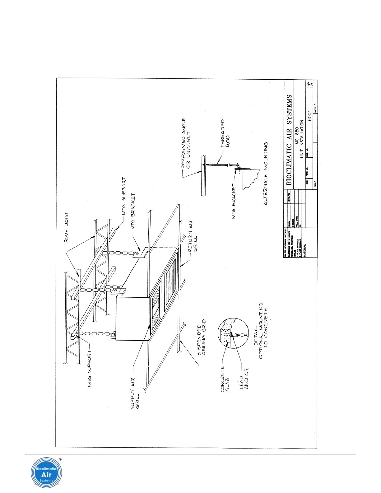
2.2 Unit Installation
The MC-880 is designed to flush mount within the standard drop ceiling T-bar grid system commonly found in most commercial
buildings. The unit should be mounted as follows:
1. Four mounting plates (with holes) are attached to the upper portion of the long sides. Remove the two outside screws and
loosen the center screw on the mounting plates. Pivot the mounting plate into a vertical position so the hole is exposed. Install
two screws and tighten the center screw.
Note: Do not support the MC-880 by any other means except the four mounting plates provided. Do not make any
penetrations into the MC-880 cabinet. Alterations to the MC-880 housing may affect system performance.
Continue on Next page

Installation, Operation & Maintenance Guide MC-880 System Series 9
1-800-394-3458 265-AUG-2021 Bioclimatic.com
2. Heavy duty wire (60 lbs. rating) or electrician’s chain should be used to support the unit by securing the upper end to a roof
support joist or beam, capable of supporting a minimum load equal to two (2) times the weight of the completely loaded unit.
In this manner, the weight of the unit is not placed directly on the ceiling grid supports. Four turn buckles may also be used if
desired to obtain precise vertical adjustment and level.
3. In order to reduce noise and vibration, the MC-880 should be isolated from the ceiling system by installing 1/4 in. W x 1/16 in.
thick PVC stripping (supplied with the unit) on the horizontal and vertical sections of the T-bar. Continuous coverage on the
T-bar is recommended to prevent metal to metal contact.
Note: Consult with local building authorities to ensure compliance with local building code ordinances.
2.3 Electrical Connections
Unit Power
Power input is 115 volt, 1 phase, 60 Hz (230 volt, 1 phase, 50/60 Hz). One circuit breaker on the right side of the unit (when facing the
end with the discharge grille) controls the blower and ionization settings. The lamp indicates operation of the bi-polar ionization
unit. High and low settings will adjust both blower speed and ionization levels simultaneously. Adjust the blower setting (high or
low) depending on the room size, amount of contamination and noise criteria. For units designed for 220/240 volts, 1 phase, 50/60
Hz; the high-low setting will adjust only ionization levels. The blower for 220/240 volt systems operates at one speed only.
Power is provided to the unit by means of a three-prong power cord connected to any standard 115 volt electrical outlet.
Remote Control Connection Option
Refer to the appendix for the schematic MC-880 Full Function Remote Control and complete all connections between remote
control from TB-3. Use 22-20 AWG stranded copper wire. Electrical codes must be followed for installing this cable.
1. Place system master switch (circuit breaker) to the “Off” position. This switch is located on the side of the MC-880 unit.
2. Connect 115 volt (220/240), single phase service lines to terminals 1,2 and 3 on TB-1. These are line, ground and neutral
respectively.
3. Double check that wire #9 on remote control, is grounded to the 2-gang electrical box and also to the aluminum face plate.
2.4 Filter Installation
When installing filters, refer to the filter label located on the unit. This label itemizes all filters in the unit and their arrangement.
Note: Make sure that airflow arrow on each filter points in the direction of airflow through the unit. Unit should not be
operated without filters in place because the lack of adequate static pressure will cause the motor to draw too much
current and potentially over-amp.
Prefilters
1. Loosen the four thumbscrews on the return (intake) grille (two on each side) and remove the entire intake assembly. On the
backside, you will find a three position filter rack with various combinations of prefilters and a metal tray (chemical filter).
2. Remove the wing nuts that hold the filter retainer in place.
Continue on Next page
Installation, Operation & Maintenance Guide MC-880 System Series 10
1-800-394-3458 265-AUG-2021 Bioclimatic.com
3. Slide the filter(s) into their respective track(s).
4. Move the filter retainer back into operating position and replace the wing nuts.
5. Replace the return (intake) grille and tighten the four thumbscrews.
Primary Filter
Primary Filter installation is accomplished through the supply or discharge (adjustable louvered) grille as follows:
1. The discharge grille is held in place with four thumbscrews and must always be installed such that center row of diffuser
blades points away from the return grille. This will prevent short cycling of air. Remove the discharge grille.
2. The Primary Filter tracking can be removed by loosening the four wing nuts holding the two angles in place.
3. Slide the filter into its track.
4. Move the two angles back into operating position and replace the wing nuts.
5. Replace the supply (discharge) grille and tighten the four thumbscrews.
Continue on Next page
CAUTION: Whenever handling primary filter, be careful to hold it by frame. Prevent any sharp objects or
fingers from coming into contact with the media pack as it is fragile and can be damaged easily.
Chemical Media Filter
The chemical media, or gas phase filter, is installed in the same way as the prefilters. Do not remove the media filter from its
sealed container until ready for use to prevent premature loading.
The life of the media filter is dependent on the type of chemical compounds present and their concentration. Air pressure
drop does not change as a function of loading; therefore it is recommended that a spare filter tray be kept on hand if loss of
contaminant removal becomes evident. Bioclimatic offers an analysis of spent media to determine remaining life and assist in the
most efficient media filter replacement schedule. Contact Bioclimatic for additional information.
Ionization
Bi-polar ionization consists of needlepoint type ion generators. The two (2) individual modules are affixed directly to the blower
inlet housing.
03 PHYSICAL DESCRIPTION
3.1 Principle of Operation
The MC-880 System is designed for filtration of environmental air so as to control particulate and gaseous contaminants for
new or retrofit HVAC applications. Please refer to the filter arrangement drawings for proper filter orientation. The filter stage
designation refers to the installation sequence in the direction of airflow.

Installation, Operation & Maintenance Guide MC-880 System Series 11
1-800-394-3458 265-AUG-2021 Bioclimatic.com
3.2 Remote Control (Optional)
These are the options which are available to the basic MC-880 Micro/Climatic Purification System:
■ Full Function Remote Control Option (24 VDC) (MC-8847A, Recessed Wall Mount)
■ Multiple Remote Control
■ Building Management System Control interface (MC-8849)
Full Function Remote Control
This option permits full operational control and status monitoring of the MC-880 from any remote location. Included are the
following functions:
Control Functions
■ On/Off control of System power (Selector switch “Local-BMS” on “Local” position)
■ High/Low motor speed selection
■ High/Low ionization level selection
■ Filter alarm test
■ Generator alarm test
Visual Indicators
■ Prefilter static pressure
■ Final Filter static pressure
■ Motor/Ionization System High
■ Motor/Ionization System Low
■ Local/BMS Control
■ Ion generator fault (alarm)
All of the operating controls and visual status indicators are arranged in a functional grouping on a 4” x 4” aluminum plate. The
plate is mounted to a standard two gang recessed electrical box using a tile ring adapter and connected using wires 20-22 AWG to
TB3 PCB 31036 in MC-880 control center box.
Multiple Remote Control
This option permits simultaneous operational control of multiple units, ranging from two to five, from any remote location. Full
function remote control is connected to the unit named “Master”.
Control Functions
■ On/Off control of system power (Selector switch “Local-BMS” for Master unit on “Local” position, for other unit(s) – “BMS” position).
■ High/Low motor speed selection
■ High/Low ionization level selection
■ Filter alarm test (for master unit)
■ Generator alarm test (for master unit)
Continue on Next page
Installation, Operation & Maintenance Guide MC-880 System Series 12
1-800-394-3458 265-AUG-2021 Bioclimatic.com
Visual indicators for Master unit are located on the FF Remote control panel.
The Master unit “Prefilter” and “Final Filter” lights are used also as an indication to determine the filter service for the rest
of the units.
Building Management System Control (BMSC)
This option also provides full operation control and filter and ionization alarm observation from any location with one or
multiple units.
The functions and indicators for the BMSC are the same as instructed previously for simple and multiple units with FF
Remote Control.
3.3 Filter Change Indicator (Lights)
As the MC-880 operates, it collects and retains particles from the air such as dust, pollen and smoke. Over a period of time, filters
installed in the MC-880 (particularly the first and second stage filters) become contaminated. As they do, the static pressure
increases across the filters in proportion to the amount of dirt collected and air flow becomes restricted. Eventually, unless filters
are replaced, air flow through the System will drop below acceptable efficiency levels.
Each MC-880 has two pressure control switches mounted inside the of the air handling unit. These devises sense static pressure
across both filter sections. They are individually adjusted at the factory to operate when differential pressure across respective
filters drops below a minimum preset threshold. Two visual indicators (Red LED) on the front louvered panel of the MC-880
respond independently to the pressure switches in the MC-880. When either of these filter alarm indicators comes “on”, its time to
change the corresponding filter.
3.4 Prefilter
Prefilters are 2 in. deep, disposable type, pleated MERV 8. Filters are listed Class 2 by Underwriters’ Laboratories.
3.5 TA Media Filter
Media filter (MC-8836F) is Bioclimatic 2 in. deep, BS 145XL extended life media.
3.6 Primary Filter
Prefilters are 4 in. deep, disposable type, pleated MERV 11. Filters are listed Class 2 by
Underwriters’ Laboratories.
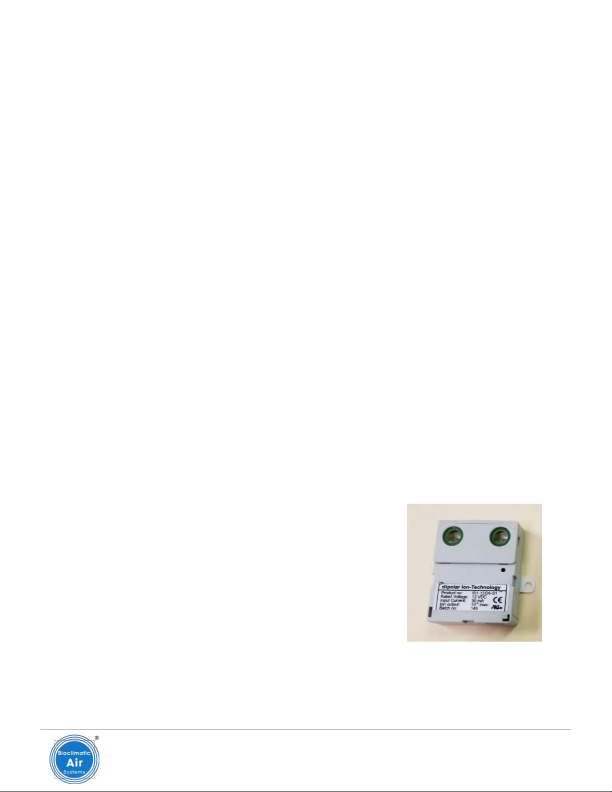
3.7 Bi-polar Ionization
The needlepoint ionizers are automatically energized with airflow (image to the right).
Periodic cleaning of the needle pairs may be necessary. Inspection that shows dust accumulation or “dull, fuzzy” needle tips is an
indication that cleaning is required. This is accomplished by using compressed air (as is used for a computer keyboard) and/or a
small brush to dislodge any particulates. Take care not the bend the needles.
Continue on Next page

Installation, Operation & Maintenance Guide MC-880 System Series 13
1-800-394-3458 265-AUG-2021 Bioclimatic.com
04 SYSTEM STARTUP
4.1 General
Before starting the system, a complete inspection should be made to ensure that all the equipment is installed and
proper operation. It is particularly important that the system is free of all foreign objects. Be sure that the access panel is
securely attached.
4.2 Inspection Check List
Filters:
■ Complete filter installation
■ Surface continuity between adjacent filters & seal surfaces
■ Unit sections are clean
Panels:
■ Insulation is intact
■ Fasteners are secure
■ Gaskets are intact
4.3 Electrical Connection & Power Up
Provide electrical connection to the system. All external wiring must be in accordance with National and Local Electrical Codes.
Pay particular attention to proper grounding of the system. After checking that all filters are in place, input electrical power is
correct, and all electrical connections are as per the National and Local codes, energize the unit. The current being supplied to the
unit should be checked after powering up the unit. It should not exceed the full load amperage.
05 OPERATION & MAINTENANCE
5.1 General
The initial set of particulate filters is included and shipped with the unit. The power to the unit can be controlled using the power
master switch (circuit breaker) on the right side of the unit. When the power switch is “On”, the unit is ready to operate using:
1. “Hi/Off/Lo” control switch on the top side of the generator (basic or standard MC-880), or
2. “Set” pushbutton on the remote-control panel (Full Function MC-880), or
3. Multiple Remote Control.
4. Building Management System Control (BMSC) (Full Function MC-880) - to energize the fan-motor, and ionization generator of
the unit. The user should determine the best mode of operation for any individual application.
Continue on Next page

Installation, Operation & Maintenance Guide MC-880 System Series 14
1-800-394-3458 265-AUG-2021 Bioclimatic.com
5.2 Standard Control
1. Turn master switch on MC-880 “ON”. This is a thermal reset switch providing overload protection to the motor and power to
the rest of the System.
2. Turn control switch on the generator to “Hi” or “Low” position. This will cause the motor speed and ionization generator to
alternately switch from high to low, or low to high status.
3. Observe visual Green LED indicator on the top of the generator confirm the operational status.
5.3 Remote Control Option
1. Turn master switch on MC-880 “ON”. (Selector switch “Local-BMS” on “Local” position).
2. Push button “Set” first time – “High”, “Local”, “Fan” and “Ion” lights will be “ON”. Unit will be ON (High – motor speed/ionization
level). Push button “Set” second time – “Low”, “Local”, “Fan”, and “Ion” Lights will be ON. Unit will be ON (Low – motor speed
ionization level). Push button “Set” third time – No lights. Unit OFF.
3. Push, momentarily, each of the three buttons marked “Test” (when unit is ON). This will cause the visual indicators marked
“Alarm”, “Prefilter” and “Final Filter” to briefly illuminate. This test will confirm that the three systems are armed and that three
visual fault indicators are functioning normally.
5.4 Multiple Remote Control (Optional)
The following must be done before the units are started:
■ Interconnect wiring between Remote Control and Master unit, between units
■ SW8 (Master unit) on PCB 31036(C) - on “Local” position
■ SW8 (units: 1-4) on PCB 31036(C) - on “BMS” position
■ Connect power (all units) to TB1 on PCB 31036(C)
■ Turn ON circuit breakers
To start unit(s) - follow above Remote Control Option steps.
5.5 Building Management System Control (BMSC)
The following must be done before the unit(s) are started.
For single unit:
■ Interconnect wiring between remote control panel and unit
■ SW8 on PCB 31036(C) - on “BMS” position
■ Connect power to TB1 on PCB 31036(C)
■ Turn ON circuit breakers
Continue on Next page

Installation, Operation & Maintenance Guide MC-880 System Series 15
1-800-394-3458 265-AUG-2021 Bioclimatic.com
For multiple units:
■ Interconnect wiring between remote control and master unit, between master unit and other units
■ SW8 (all units) on PCB 31036(C) - on “BMS” position
■ Connect power (all units) to TB1 on PCB 31036(C)
■ Turn ON circuit breakers
To start unit(s) - follow above Remote Control Option steps.
5.6 Filter Change Light Adjustment
CAUTION: Disconnect all power before opening doors for service or maintenance. Observe routine
precautions when servicing unit.
The fibrous filters and optional gas phase filtration section require periodic maintenance in order to ensure satisfactory system
performance over an extended period. The filter change light indicates the need to replace fibrous filters. The differential pressure
switch which activates the filter change light is preset at the factory to light when a static pressure increase of approximately 1 in.
WC (249 Pa) occurs.
It is possible to calibrate the static pressure differential which illuminates the filter change light as follows:
1. Remove the hole plug in the top of the unit for access to the adjustment screw.
2. With clean filters, turn the unit on cover approximately 67% of the return grille with cardboard. The light should come on.
3. For more time between filter changes (less air flow), cover more of the opening and for less time between changes (more air
flow), cover less of the opening.
4. With a standard screwdriver, turn the adjustment screw clockwise until the light goes off, or counterclockwise until the light
comes on.
5.7 Filter Maintenance
Particulate Filters:
When the filter change light illuminates, it is time to replace the particulate filters. It is important to use high quality filters with
the same specifications as those provided with the unit. The filter label affixed on the inside of the access door lists the part
number of the filters supplied with the unit. Refer to the specifications for optional features for the specifications of the proper
replacement filters for your unit. Be sure filters are installed in the correct position for airflow.
Ionization Modules
Needlepoint ionizers are not consumable devices but may require periodic cleaning.
Continue on Next page

Installation, Operation & Maintenance Guide MC-880 System Series 16
1-800-394-3458 265-AUG-2021 Bioclimatic.com
Laboratory Service (Gas Filtration Media Life Analysis)
Laboratory analysis is a support service offered to our customers. This service will ensure timely media change out for cost
effective and efficient system operation.
Media Sampling Procedure
1. Remove and replace the media filter. Tag the filter to be analyzed as “For Test”, and mark the job name, location, and unit
model number on the plastic bag (recommend sing the bag that comes with the replacement filter.
2. This bag should be sealed to prevent any further exposure to the air.
3. Ship the labeled media filter to:
Bioclimatic Air Systems
600 Delran Parkway
Delran, NJ 08075
Attn: Laboratory Supervisor
5.8 Gasket Replacement
After a period of operation, the gasketing on the unit may need to be replaced. It is important to replace it only with closed cell
neoprene gasketing. Do not use rubber gasketing as it is not suitable for use in this application.
Installation, Operation & Maintenance Guide MC-880 System Series 17
1-800-394-3458 265-AUG-2021 Bioclimatic.com
06 APPENDICES

Installation, Operation & Maintenance Guide MC-880 System Series 18
1-800-394-3458 265-AUG-2021 Bioclimatic.com

Installation, Operation & Maintenance Guide MC-880 System Series 19
1-800-394-3458 265-AUG-2021 Bioclimatic.com

Installation, Operation & Maintenance Guide MC-880 System Series 20
1-800-394-3458 265-AUG-2021 Bioclimatic.com
This manual suits for next models
3
Table of contents
Other Bioclimatic Air Cleaner manuals


