Biogents BG User manual

Updates for the manual can be found on the website www.bg-counter.com
Status: September 2018 BG-CounterTM
Mosquito Control
Instruction Manual

2EN
The BG-Counter is an electronic device that counts mosqui-
toes as they y through and wirelessly transmits the data to
a cloud server. Dierentiation of mosquitoes from smaller or
larger insects, and from other objects such as dust or rain
particles, is based on the size and wing beat frequency. Mos-
quitoes, small Diptera such as chironomid midges and fungus
gnats, and other insects with a similar size cannot be reliably
dierentiated. Therefore, to improve classication accuracy,
the BG-Counter utilizes carbon dioxide (CO2) to attract only
blood sucking insects. By using CO2as an attractant the ac-
curacy of correctly counted mosquitoes is in the range of
80-90 %. Accuracy may vary from location to location and
should be veried from time to time (see accuracy of counts).
Description of the BG-Counter
It is strongly recommended to use the BG-Counter in combi-
nation with a BG-Sentinel trap that removes the insects after
they are sucked through to avoid multiple counts of the same
insect. To insure accurate counts, the trap must not allow
collected mosquitoes to escape.
Equipped with basic sensors, the BG-Counter also samples
local environmental data such as temperature, humidity
and light. The system is supported by a web application for
storage of mosquito counts as well as geospatial and envi-
ronmental data. Via this web application you can remotely
switch the trap and the BG-Counter on and o. It also allows
you to set up varying time schedules to run the trap and con-
trol the application times of CO2.
The BG-Counter needs mobile reception to transmit data to
the web server. Therefore place the BG-Counter with the trap
only in areas with mobile reception. You can check the local
reception with your mobile phone.
BG-Counter needs mobile reception
The BG-Counter will automatically select the mobile provi-
der that is available at the chosen location.
See page 10 for rst-time user registration.
Registration

3EN
Table of Contents
Description of the BG-Counter. . . . . . . . . . . . . . . . . . . . . . . . . . . . . . . . . . . . . . . . . . . . . . . . . . . . . . . . . . . . . . . . . . . . . . . . . . . . . . . . . . . . . . . .
The BG-Counter needs mobile reception . . . . . . . . . . . . . . . . . . . . . . . . . . . . . . . . . . . . . . . . . . . . . . . . . . . . . . . . . . . . . . . . . . . . . . . . . . . . . . .
Product Components . . . . . . . . . . . . . . . . . . . . . . . . . . . . . . . . . . . . . . . . . . . . . . . . . . . . . . . . . . . . . . . . . . . . . . . . . . . . . . . . . . . . . . . . . . . . .
How to Set-Up the BG-Counter with the Trap . . . . . . . . . . . . . . . . . . . . . . . . . . . . . . . . . . . . . . . . . . . . . . . . . . . . . . . . . . . . . . . . . . . . . . . . . . . . .
Connect CO2. . . . . . . . . . . . . . . . . . . . . . . . . . . . . . . . . . . . . . . . . . . . . . . . . . . . . . . . . . . . . . . . . . . . . . . . . . . . . . . . . . . . . . . . . . . . . . . . . . . . . . . .
Connecting the BG-Counter to Power: 3 Option . . . . . . . . . . . . . . . . . . . . . . . . . . . . . . . . . . . . . . . . . . . . . . . . . . . . . . . . . . . . . . . . . . . .
Calibration . . . . . . . . . . . . . . . . . . . . . . . . . . . . . . . . . . . . . . . . . . . . . . . . . . . . . . . . . . . . . . . . . . . . . . . . . . . . . . . . . . . . . . . . . . . . . . . . . . . . . . . . . .
Operating the BG-Counter. . . . . . . . . . . . . . . . . . . . . . . . . . . . . . . . . . . . . . . . . . . . . . . . . . . . . . . . . . . . . . . . . . . . . . . . . . . . . . . . . . . . . . . . . . . . .
First Cloud Connection. . . . . . . . . . . . . . . . . . . . . . . . . . . . . . . . . . . . . . . . . . . . . . . . . . . . . . . . . . . . . . . . . . . . . . . . . . . . . . . . . . . . . . . . . . . . . . . . . .
Reset . . . . . . . . . . . . . . . . . . . . . . . . . . . . . . . . . . . . . . . . . . . . . . . . . . . . . . . . . . . . . . . . . . . . . . . . . . . . . . . . . . . . . . . . . . . . . . . . . . . . . . . . . . . . . . . .
BG-Counter Webseite Description . . . . . . . . . . . . . . . . . . . . . . . . . . . . . . . . . . . . . . . . . . . . . . . . . . . . . . . . . . . . . . . . . . . . . . . . . . . . . . . .
Registration at live.bg-counter.com . . . . . . . . . . . . . . . . . . . . . . . . . . . . . . . . . . . . . . . . . . . . . . . . . . . . . . . . . . . . . . . . . . . . . . . . . . . . . . . .
Dash Board . . . . . . . . . . . . . . . . . . . . . . . . . . . . . . . . . . . . . . . . . . . . . . . . . . . . . . . . . . . . . . . . . . . . . . . . . . . . . . . . . . . . . . . . . . . . . . . . . . . . . . .
Main Menu . . . . . . . . . . . . . . . . . . . . . . . . . . . . . . . . . . . . . . . . . . . . . . . . . . . . . . . . . . . . . . . . . . . . . . . . . . . . . . . . . . . . . . . . . . . . . . . . . . . . . . .
User Administration. . . . . . . . . . . . . . . . . . . . . . . . . . . . . . . . . . . . . . . . . . . . . . . . . . . . . . . . . . . . . . . . . . . . . . . . .. . . . . . . . . . . . . . . . . . . . . . .
Assignment and Adding Additional BG-Counters . . . . . . . . . . . . . . . . . . . . . . . . . . . . . . . . . . . . . . .. . . . . . . . . . . . . . .. . . . . . . . . . . . . .
Trap Page . . . . . . . . . . . . . . . . . . . . . . . . . . . . . . . . . . . . . . . . . . . . . . . . . . . . . . . . . . . . . . . . . . . . . . . . . . . . . . . . . . . . . . . . . . . . . . . . . . . . . . . . . .
Troubleshooting. . . . . . . . . . . . . . . . . . . . . . . . . . . . . . . . . . . . . . . . . . . . . . . . . . . . . . . . . . . . . . . . . . . . . . . . . . . . . . . . . . . . . . . . . . . . . . . . . . . .
Technical Data for BG-Counter . . . . . . . . . . . . . . . . . . . . . . . . . . . . . . . . . . . . . . . . . . . . . . . . . . . . . . . . . . . . . . . . . . . . . . . . . . . . . . . . . . . . . .
Contact. . . . . . . . . . . . . . . . . . . . . . . . . . . . . . . . . . . . . . . . . . . . . . . . . . . . . . . . . . . . . . . . . . . . . . . . . . . . . . . . . . . . . . . . . . . . . . . . . . . . . . . . . . . . . .
2
2
4
5
7
7
8
9
9
9
10
10
11
11
12
12
13
17
19
19

4EN
1. BG-Counter
1.1. Body
1.2. Antenna (female SMA connector)
1.3. Antenna connector
1.4. 12 V power connector
1.5. Fan connector (red) with attached fan adapter cable
1.6. CO2input port with attached CO2tube
1.7. CO2release port
1.8. Pressure regulator, two versions:
a) preset regulator
b) adjustable regulator
1.9. Battery adapter cable
1.10. AC power cord with transformer
2. Solar system
2.1. Solar panel with connectors
2.2. Solar controller with connectors
2.3. Battery cable, already connected to solar controller
2.4. Load adapter cable
3. BG-Trap Station
3.1. BG-Sentinel 2 trap
3.2. Rain shelter (plastic)
3.3. Metal stand with base: 2 rings, 1 stake
Product Components
1.9
1.3.
1.4
1.7
1.8
3.1
3.2
1.1
1.5
1.6
1.10
2.1
2.2
2.3
2.4
3.3
3.3
1.2.
a) b)

5EN
Two options:
Option 1: You have ordered a BG-Counter without BG-Trap
station, see below, same page.
Option 2: You have ordered a BG-Counter with BG-Trap sta-
tion, see page 6.
Option 1: You have ordered a BG-Counter without BG-Trap
station:
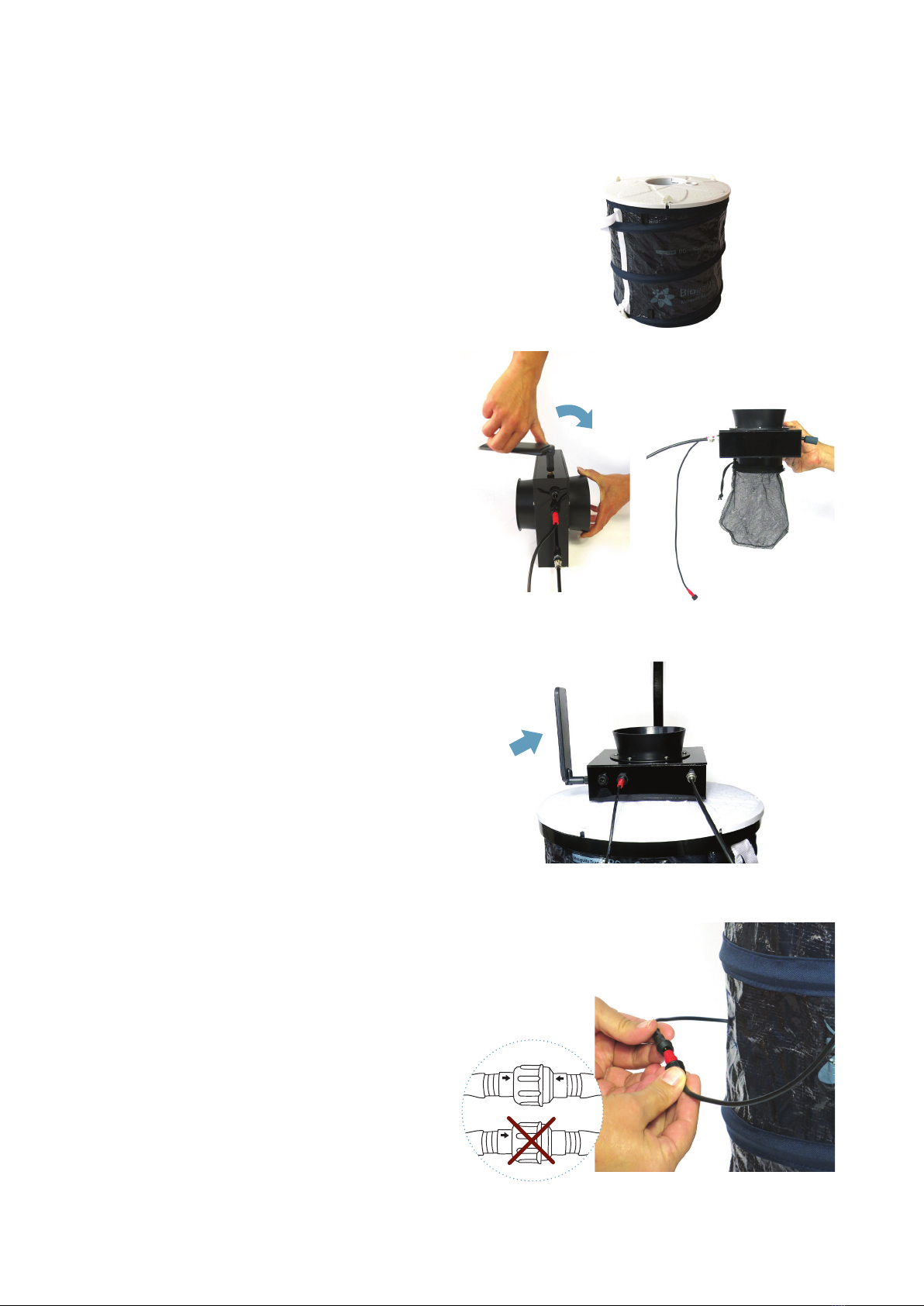
1. Assembling your BG Sentinel:
Do not place the funnel into the opening on top of the
cover [see Fig. F1]. The BG-Counter will be placed here
later on.
2. Fix the antenna on the BG-Counter: Place the BG Coun-
ter on a at surface with the antenna connector facing
up [F2]. Screw on the antenna, turning in a clockwise mo-
tion until rmly attached. Do not overtighten the screw.
3. For routine operation of the counter, it is recommended
to not install a catch bag.
A catch bag and funnel net can be installed when the
trap and counter are run overnight or for a few hours,
and the catch is to be preserved for inspection:
Attach catch bag to the bottom part of the counter (if
desired) [F3].
For more information about this topic see chapter “De-
termination of Counting Accuracy”.
4. Place the BG-Counter into the opening on top of the
trap. Turn the antenna to an upright position [F4].
5. Connecting the fan to the counter: Connect the red fan
adapter cable with the fan cable coming out on the side
of the trap. Please pay attention to always connect with
the arrows in one line [F5].
Next steps are
• Connect CO2, see page 7
• Connecting the BG-Counter to power, see page 7
How to Set-Up the BG-Counter with the Trap
F2
F3, optional
F5
F2
F4
F1
1.1

6EN
Option 2: You have ordered a BG-Counter with BG-Trap
station:
1. Assemble the BG Sentinel
Follow assembly instructions for the BG Sentinel 2. See
manual at www.biogents.com or bg-sentinel.com, but do
not place the funnel into the opening on top of the cover
[F6]. The BG-Counter will be placed here later on.
2. Assemble stand
Assemble the lower part of the stand by placing the sta-
ke in the holder of the rst ring and xing it with the
screw. Adjust second ring about 25 cm below top of the
stake [F7].
3. Set up BG Sentinel in stand [F8].
4. Fix the antenna on the BG-Counter: Place the BG Coun-
ter on a at surface with the antenna connector facing
up (see Fig F9). Screw on the antenna, turning in a clock-
wise motion until rmly attached. Do not overtighten the
screw.
5. For routine operation of the counter, it is recommended
to not install a catch bag.
A catch bag can be installed below the ventilator when
the trap and counter are run overnight or for a few hours,
and the catch is to be preserved for inspection:
Attach catch bag to the bottom part of the ventilator (if
desired) [F10].
For more information about this topic see chapter “De-
termination of Counting Accuracy”.
6. Place the BG-Counter into the opening on top of the
trap. Turn the antenna to an upright position [F11]
7. Connecting the fan to the counter: Connect the red fan
adapter cable with the fan cable coming out on the side
of the trap. Please pay attention to always connect with
the arrows in one line [F12].
8. Install rain shield
Install rain shield about 15 cm above top of counter fun-
nel [F13].
F13
15 cm
25 cm
F10, optional
F12
F8
F7
F9
F11
F6
Next steps are
• Connect CO2, see page 7
• Connecting the BG-Counter to Power, see page 7

7EN
The CO2bottle is not included, and must be provided by the
user.
There exist two dierent versions of the pressure regulator:
a) The preset regulator is adjusted to 2.0 bar and the outlet
pressure cannot be changed.
b) The adjustable pressure regulator must be set at 1.5 kg/
day (corresponding to 2.6 bar).
The ttings of the regulators are either US CGA-320 or Euro-
pe W21.8x1/14 RH standards.
Connect CO2
F15
F14
1. Install the CO2pressure regulator on tank and make sure
it is tight by using a wrench or pliers [F14].
2. Connect the free end of the CO2tubing to the regulator
[F15]: unscrew the nut on the outlet, thread the end of
the CO2tube through the nut, insert the end of the CO2
tube rmly onto the outlet and re-screw the nut back
onto the outlet.
3. Now open the valve on the top of the CO2bottle to start
the release of CO2.
Option 1
Power cord with transformer
This is recommended if AC power is available at the counter location.
• Use only the provided AC adapter, and conrm local outlet style before
ordering:
• US: Nema 1-15
• Europe: CEE 7
Connecting the BG-Counter to Power: 3 Options
3 options to connect the
BG-Counter to power via
the 12 V power connection

8EN
Option 2
12 V battery (provided by user)
This is recommended if the counter is operated in a location for a few days,
before being serviced or moved. The minimum number of hours of operation
possible with a full battery can be calculated as follows:
Operation hours = Battery capacity (Ah) x 2.
For example, with a battery capacity of 60 Ah (Ampere hours), the counter and
fan can be operated for at least 60 x 2 = 120 hours = 5 full days.
Use “deep cycle” lead-acid, or lithium-ion batteries. Normal car batteries are not
designed for continuous charge/discharge cycling, and thus would have signi-
cantly reduced lifetime.
• Connect battery using battery cable
Option 3
Solar panel with solar battery
This is recommended when the system needs to be operated autonomously for extended periods of time.
While the trap/Counter are usually placed in a shady location, the solar panel should be placed in a sunny
spot nearby; the solar controller and battery should be placed near the counter.
Solar controller
F16.1
F16.2
F16.3
Determination of Counting Accuracy
For routine operation, it is not recommended to use a catch
bag as the catch bag might be lled up too quickly. In this
way mosquitoes will be sucked through the ventilator and
end up dead at the bottom of the trap.
However, a catch bag can be installed when the BG-Counter
runs only for a few hours in order to check if the number
of counted mosquitoes by the BG-Counter corresponds
with the actual number of collected mosquitoes. In this way
the accuracy of the BG-Counter can be determined. When
comparing manual catch bag counts to electronic counts, it
should be noted that mosquitoes can “disappear” from the
catch bag:
Mosquitoes and other insects may be “stolen” by ants, spi-
ders, or geckos. For all calibration experiments make sure
that ants or other predators have no access to the catch bag.
You can protect the trap and catch bag by a water surface
around the trap, or by adding glue or PTFE to all trap parts
that might be accessible for predators.
If you make sure that mosquitoes do not leave the catch bag
after they have been sucked in the accuracy of the BG-Coun-
ter for correctly counted mosquitoes is between 80% and
90% correctly counted mosquitoes. If desired, experiments
can be performed from time to time to compare the catch
bag results with the electronic results reported for the same
time interval.
• Solar panel and solar controller are deliverd already connected [F16.1].
• Connect battery clamps to the battery (battery cables are delivered already con-
nected to the solar controller) [F16.2]. Pay attention to connect minus-pole to
minus-pole (black) and plus-pole to plus-pole (red).
• Connect the load cable to the BG-Counter [F16.3]

9EN
1. Automatic start-up
The BG-Counter has no on/o switch or other buttons.
It automatically starts when connected to 12 V power.
2. Battery check
After the counter is connected to power, there will be from 1
to 4 beeps, depending on battery voltage.
• 4 beeps mean the battery is fully charged
• 3 beeps means the battery is not full, but suciently char-
ged to allow normal operation of the counter
• If only 1 or 2 beeps are heard, this means the battery is
low and needs charging, and counting function, fan, and
CO2 will be o
• If there is no beep at all, see chapter Troubleshooting /
Trap does not start up
3. Cellular connection check
Following the battery check, the device proceeds to check
the strength of the cellular connection. This usually takes
less than 30 seconds, but may take several minutes, for ex-
ample, if the counter has been moved to a new location with
a dierent cellular provider.
At the end of the check, the counter indicates signal strength
as follows:
Operating the BG-Counter
• 1-5 long beeps: corresponding to 1-5 bars of signal
• 2 short beeps: no signal, no cellular connection possible
If no cellular connection is available, the counter can still be
operated. Data will be stored internally, and transmitted the
next time a connection is available.
4. Fan and CO2 ow check
After powering up, the fan and CO2valve are switched on
until the next round 15 minute interval (for example, if pow-
ered up at 16:03 until 16:15). This provides time for the ope-
rator to conrm that the Sentinel 2 fan is, indeed, working,
and the CO2 ow is on.
Conrm fan operation visually by looking into the trap fun-
nel, or by holding a piece of tissue paper above the funnel.
By default, the CO2 ow is adjusted to 50 g/h. The CO2dosing
valve is located inside the counter housing. It briey turns
on and o every 4 seconds.
Check for the presence of CO2 ow as follows:
• pressure at regulator set to 2 bar
• audible click from the valve
• hiss from the CO2release port
5. Counter check
If desired, the function of the counter can be veried at this
time by throwing a small object (for example, a small piece of
paper) into the trap funnel. A short beep is heard, indicating
the counter has registered the object.
The rst connection to the Cloud (http://www.bg-counter.
com) takes place at the rst round 15 minutes after the coun-
ter is started (for example, 16:15).
When connecting to the cloud, results are uploaded, and the
schedule dened on the web site is downloaded and acti-
vated.
First Cloud Connection
Reset
The BG-Counter is reset every time the power is disconnected and re-connected, and the start-up sequence commences as
described above.
Depending on the schedule, fan, CO2and/or counting
function may be turned o at this time.
If this is a new counter, the rst connection also auto-registers
the counter on the website.
Maintenance
Check the BG-Counter and trap bi-weekly or once a month for functionality, remove everything that deters mosquitoes from
entering the trap such as spider webs, leaves and any dirt and keep the white cover as clean as possible.

10 EN
The web application allows you to remotely switch traps in
the eld on and o. It also allows you to set up varying time
schedules to run the traps and to set up application times
of attractants. Further you have access to all collected data
including local environmental data such as temperature, hu-
midity, or light.
BG-Counter Website Description
On the website and in these instructions, the word “trap” re-
fers to a complete system including a trap and a counter.
The website address is live.bg-counter.com. Any modern web
browser (PC, tablet, or mobile phone) can be used to access
the website.
No registration is necessary to view the traps in the “Demo”
account.
To take advantage of the full functionality of the website,
you must rst be registered.
Registration for the Administrator (there is only one Admi-
nistrator for each company):
• go to live.bg-counter.com and click on „Register“
• enter your e-mail address
• re-enter your e-mail address to make sure it’s correct
• enter the serial number of the counter (IMEI, located on
a sticker on the bottom of the counter): select from the
left hand side (1) the number that ts to the rst digits
of your serial number. Then add the last 7 digits in the
right eld.
Registration at live.bg-counter.com
You will receive a conrmation e-mail (please have also a
look for the e-mail in your spam folder) with a temporary
password and a link to activate your account.
Now you are a registered customer.
Log-in:
To check and control the counter, go to live.bg-counter.com:
• log-in with your e-mail address and your temporary pass-
word
• click on “Prole” to set a new password for your account
• click on “Trap Management” to set the counter name,
schedule etc
• click on “User Management” to invite other users, such as
operators and guests
If you have more than one counter, you can add them to your
account in “Trap Management”.
1

11EN
Once logged-in, the dashboard shows an overview over your traps in a map (2). When managing multiple traps, the location
display is convenient to conrm which trap is located where. That location is displayed using a label in Google Maps. You can
zoom in and out, and switch between a map display and a satellite image (3).
Active traps are shown in green, and inactive traps are shown in red.
Also the traps are listed below the map in a short overview with daily captures (4).
Dashboard
• Administrators can view all traps belonging to their organisation
• Guests can only see assigned traps
Viewing a trap and schedule CO2, fan and counter:
For each trap there is an own page with more details and the possibility to set a timer for CO2release and fan and counter
operation. There are several convenient ways to access a trap page:
• In the “Dashboard”, click on a trap name either in the map or in the list below the map
• In “Your Traps” (main menue left side), click on a trap name
• In “Trap Management” (main menue left side), click on a trap name or click on “View”
2
3
Main Menu
Beside the dashboard you nd following topics in the main menu (5):
Trap Management
• Provides a list of traps with serial number information and links for viewing and controlling traps
Prole
• Allows a user to change passwords
Users (“Administrator” and “Operator” only)
• Allows to invite and delete users
Your Traps
• Provides shortcuts to the available traps (6)
5
6
4

12 EN
How to assign BG-Counters to the dierent users:
Assignment to a new “Operator” (“Administrator” and
“Operator” only)
• Click on “Users”
• Fill out the form for inviting a new operator: Enter the
e-mail address, choose „Operator“ in the Role eld, and
write - if you wish - a comment for the new user.
• Choose the BG-Counters the operator can view and
control
• Click the “Invite” button
Assignment to a new “Guest” (“Administrator” and “Opera-
tor” only)
• Click on “Users”
• Fill out the form for inviting a new guest: Enter the e-mail
address, choose „Guest“ in the Role eld, and write - if
you wish - a comment for the new user.
• Choose the BG-Counters the guest can view
• Click the “Invite” button
Assignment and Adding Additional BG-Counters
Assigning a BG-Counter to an existing “Operator” or “Guest”
(“Administrator” and “Operator” only)
You have two possibilities to do this:
First possibility
• Click on “Trap Management”
• Find the BG-Counter to be assigned, and click on “Users”
• In the “Assign Trap to User” screen, select an operator or
guest from the drop-down list
• Click “Assign”
Second possibility
• Click on “Users”
• Find the operator or guest to whom you want to assign a
trap
• Click on the blue button “Traps”
• In the “Assign Trap to User” screen choose the trap in the
drop down list
• Click the “Assign” button
Administration Roles and Rights
We have three types of users:
“Administrator”
• Registers BG-Counters
• Can view and control the registered BG-Counters
• Can appoint operators and/or guest
• Can delete operators and guests
• Can assign BG-Counters to operators and guests
• Can remove BG-Counters from operators and guests
“Operator”
• Can view and control the BG-Counters assigned to him/
her
• Can appoint operators and/or guest
• Can delete operators and guests
• Can assign his BG-Counters to operators and guests
• Can remove his BG-Counters from operators and
guests
“Guest”
• Can only view (but not control) assigned BG-Counters.
How to add additional BG-Counters (“Administrator” only):
• In “Trap Management”, click on the “Add Trap” button.
• Enter a name for the BG-Counter
• Enter the IMEI (International Mobile Equipment Identity).
The IMEI is printed on a sticker on the bottom of the coun-
ter module. You only need to enter the last 7 digits, the
rst 8 digits are already pre-lled)
• Click on “Create”

13EN
After selecting and clicking a trap, the trap page is shown. Here you nd all of the data belonging to the trap inclusive capture
data. Further you can set a timer for CO2release and fan and counter operation.
Trap Location
On top of the trap page the trap location is shown in a Google map.
Types of coordinates
Location is normally determined using the build-in GPS. If
no GPS x is available, an estimated location is provided
using triangulation of the cellular signal. With “zoom in“ the
dierent circles will get visible:
GPS Location: Green circle, accuracy about 50 m (8)
Cellular Location: Red circle, accuracy about 10 km (7)
Setting “Exact” coordinates
Since mosquito counts are strongly correlated with exact
trap location (down to the nearest bush perhaps), it is possi-
ble to use Google Maps to set the exact location of the trap.
Click on the pencil icon next to “Trap Location” (9). Now, an
arrow is shown below the trap label which points to the exact
location. Click and drag the label to the desired location,
zooming in and switching between map and satellite view
as required. The location is saved when clicking on an item
outside the map.
Default location
If a newly registered trap has not yet transmitted a location
signal, the location displayed will be either the last known
location (which can be some distance away from the present
location) or the location of the prime meridian in Greenwich,
UK.
The location displayed is the last known location. For histo-
ric data, the best estimate of the location on the day selected
in the main chart is shown.
Trap Page
9
78

14 EN
Trap Information
The trap information in the right box provides general data
to your trap like name, IMEI (International Mobile Equipment
Identity), last connection, and level of CO2cylinder.
For changing these data, click on the pencil icon next to the
“Trap Information” (10):
Name
To change, click on the text eld, and enter the new name
(11).
CO2cylinder
On the main trap page, an estimate is provided for the cur-
rent ll status of the CO2cylinder, and the time left until em-
pty. For the estimate to be correct, it is necessary to have a
xed schedule, and to indicate when the cylinder was last
lled.
Cylinder size (kg)
Click on “Please select” or the current size, and pick a size
from the drop-down list (12).
Fill
Click on the “Fill” button, and then select the date and time
at which the cylinder was last lled (13).
Flow rate
The ow rate is automatically set to 50 g/h. This is the opti-
mum number for operation of the BG-Counter to attract mos-
quitoes while at the same time repelling other insects. This
eld cannot be edited.
Data connection
Determines how often the counter will try to connect to
the website, and transmit counts and other data (14). The
default is every 15 minutes. Other choices are every 1, 2,
4, and 8 hours (Independent of this setting, count data are
always stored with 15-minute resolution).
The 15-minute setting is useful for diagnostics when the
counter is rst set up. However, during each transmission,
counting stops for 15-120 seconds, depending on the cellu-
lar signal strength. This can result in a small undercounting
error. In order to minimize this error, a data connection pe-
riod of 1 hour or longer is recommended for routine opera-
tion.
A new setting is transmitted at the next data connection, i.e.
if previously the interval was set to 4 hours, and now an in-
terval of 1 hour is desired, it may take up to 4 hours until the
new setting is transmitted.
Raw data transmission
This is a diagnostic feature. Leave all switches “o” unless
advised dierently by Biogents.
Save
Click on “Save” to save any changes that were made (15), or
click on your browser’s back button to return to the previous
page without saving the changes.
10
11
12
13
14
15

15EN
Trap Schedule
18
The trap schedule is used to control the operation of the trap: Here you can set a timer for the CO2release and the operation
of the fan and the counter For each 15-minute interval during a day, the on/o status can be selected for the following:
• CO2: green = on, white = o.
• Fan: blue = on, white = o.
• Counter: orange = on, white =o.
To change the schedule, click on the pencil icon next to “Trap
Schedule” (16).
These elds can be set independently, although normally
they are all on at the same time. However, if for example a
catch bag is installed, and the catch is to be retained for coll-
ection, leave the fan on continuously.
Normally, the schedule is set to repeat daily; however, it can
also be set dierently for every day of the week (17).
16
Clicking and dragging changes the status (click on the circle
with a question mark for a short demo (18)).
Click on “Save” to save the new schedule, or click on your
browser’s back button to return to the previous page without
changing the schedule.
A new schedule is downloaded to the trap, and becomes
eective at the time of the next data connection (see Data
Connection in the “Trap Information“).
Edit the trap schedule:
17

16 EN
Chart settings
Here you can view the captures of your trap.
List
Click on “List” to see trap counts as well as status data dis-
played below the main chart (25). If the battery voltage is
getting low, it can be seen here. Also, the cellular reception
level is indicated; numbers of -113…-100 dB indicate a weak
signal, and data transmissions may become irregular.
Exporting data into Excel
Clicking on the Export button brings up the “Export Data”
window (26). Here you can select a date range for export,
whether data are exported from 0-24 hours or 12-12 hours,
and the format of the export le (EXCEL or CSV, comma-se-
parated values.)
Daily charts
Scroll down below today’s chart, and click on “Load Daily
Charts” to display small charts for the last 30 days (27). This
is a convenient way to spot trends.
Note: Since a large amount of data is searched, it may take
up to 20 seconds or more to update the display.
Accessing historical data
Data are stored and presented for 15 minute intervals. All
times are local time at the last known location of the trap.
Chart settings
In Chart Settings, you can select for display:
• Insect Types (Mosquitoes, Large Objects, Small Objects)
(19): Press the „Insect Types“ Button to see and select your
choice of insect types that will be shown in the chart.
• Date and time window (0-24 hours or 12 noon to 12 noon)
(20)
• Mosquito Sum (sum of counts for periods during which the
counter is on) (21)
• y-Axis range (22)
Main chart
When a trap is called up, today’s data are shown in the main
chart. Click on “< Previous Day”> or >“Next Day >” to navi-
gate day-by-day (23).
Color bars across the chart indicate the times during which
CO2, fan and counter, respectively, were turned on.
Small grey circles on top of the chart indicate the times at
which data connections took place (24).
Clicking on the chart displays the counts for the nearest 15
minute interval.
19
20 21 22
23
24
25 26
27

17EN
Trap does not start up
Symptoms:
• No beeps after connecting power
• Fan not working
• CO2valve not clicking
• A blue glow may be visible when looking into the coun-
ter funnel
Cause: No power or wrong polarity
Solution: Check voltage, continuity, and polarity on the po-
wer connection.
Only one or two beeps upon start-up
Symptoms: Counter, fan and CO2 valve are o. No data
transmission.
Cause: Battery is too low.
Solution: recharge battery, or replace with full battery.
Cellular signal too low
Symptoms: Two short beeps about 1-2 minutes after con-
necting the trap to power.
Cause: Weak or no cellular reception at the present loca-
tion of trap.
Solutions:
• Move trap to a location which has stronger reception
• Connect an external high-power antenna (contact Bio-
gents for information)
• Continue using the trap: data will be saved and uploa-
ded upon the next time there is reception
Cellular transmission stops
Symptom: Counter stops transmitting data even though
cellular signal strength is good.
Cause: Extremely low battery (<11.2 V). To protect the
counter from damage, the electronics, fan and CO2are shut
down. In order to view the last transmitted battery voltage,
go to the the trap page and press the “List” button.
Note: A 12 V battery is considered 0 % charged when the
voltage is below 11.8 V.
Solution: Replace or charge battery.
Irregular transmission times
Symptoms:
• Trap doesn’t transmit data when scheduled
• Irregular spacing of connection circles in main chart
Causes: Weak cellular connection or cellular network busy.
Solution: Data will be stored and transmitted at next suc-
cessful connection.
Solar battery voltage gradually drops
Symptom: When viewing “List” data, it is observed that
the solar battery is not maintaining voltage. Eventually,
counting and transmission of data stops.
Cause: Not enough sunlight to keep solar battery charged.
Solutions:
• Modify schedule to only measure during peak hours of
mosquito activity
• Move solar panel to a sunnier position
• In rare cases, a larger solar panel may be needed. Con-
tact Biogents
Troubleshooting

18 EN
Counting errors (fan failure)
Symptoms:
• Mosquito counts may appear low
• Small counts may appear high
• Catch bag (if used) may be empty
• When viewing “List” data, Power Draw is near 0, even
when fan is supposed to be on
Cause: Fan has failed.
Solution: Check fan wiring; if necessary replace fan.
Counting errors (overcounting)
Symptom: Fewer mosquitos in catch bag than counts on
website.
1.Cause: Mosquitos might be able to escape if the catch
bag is full or due to a reduced air ow and spatial vicini-
ty to the funnel. When leaving the trap, the mosquitoes
sometimes cross the infrared barrier several times (28)
and are therefore also counted several times (29).
Solution:
A) Remove the funnel net and catch bag (30).
B) In case you need to analyze the mosquitoes, install a
catch bag below the fan (31).
2. Cause: Mosquitoes were “stolen” by other insects (e.g.
ants)
Solution:
Place the trap ant-protected, e.g. in a water bath or grea-
se the basement with petroleum jelly.
Counting errors (undercounting)
Symptom: More mosquitos in catch bag than counts on
website.
Cause: Some mosquitoes were misclassied as large.
Solution: An 80% or higher accuracy is normal. If the-
re are no other large objects in the catch bag, use the
sum of mosquito and large object counts (activate un-
der “Chart settings“/“Insect types“ “Large objects“). Add
both together, accuracy may increase.
Troubleshooting
28
29
30
31
mind. 15 cm mind. 15 cm

19EN
Biogents AG
Weißenburgstr. 22
93055 Regensburg
Germany
www.biogents.com
Email: [email protected]om
Contact
Weight (Body): 730 g
Dimension (Body): 23 x 23 x 14 cm
BG-Counter including ventilator: 12V DC, 7 Watt
Switching power supply: AC Input 100 – 230V,
Frequency 60Hz/50Hz,
DC Output 12V 1A
Technical Data for BG-Counter
Mosquito Control
Other manuals for BG
2
Table of contents
Other Biogents Cash Counter manuals