Biogents BG-Counter User manual

Updates for the manual can be found on the website www.bg-counter.com
Status: July 2020 BG-CounterTM
Instruction Manual

2EN
Table of Contents
Description of the BG-Counter. . . . . . . . . . . . . . . . . . . . . . . . . . . . . . . . . . . . . . . . . . . . . . . . . . . . . . . . . . . . . . . . . . . . . . . . . . . . . . . . . . . . . . . .
The BG-Counter needs mobile reception . . . . . . . . . . . . . . . . . . . . . . . . . . . . . . . . . . . . . . . . . . . . . . . . . . . . . . . . . . . . . . . . . . . . . . . . . . . . . . .
Product Components . . . . . . . . . . . . . . . . . . . . . . . . . . . . . . . . . . . . . . . . . . . . . . . . . . . . . . . . . . . . . . . . . . . . . . . . . . . . . . . . . . . . . . . . . . . . .
How to Set-Up the BG-Counter with the BG-Trap Station. . . . . . . . . . . . . . . . . . . . . . . . . . . . . . . . . . . . . . . . . . . . . . . . . . . . . . . . . . . . . .
Connect CO2. . . . . . . . . . . . . . . . . . . . . . . . . . . . . . . . . . . . . . . . . . . . . . . . . . . . . . . . . . . . . . . . . . . . . . . . . . . . . . . . . . . . . . . . . . . . . . . . . . . . . . . .
Connecting the BG-Counter to Power: 3 Options . . . . . . . . . . . . . . . . . . . . . . . . . . . . . . . . . . . . . . . . . . . . . . . . . . . . . . . . . . . . . . . . . . . .
Determination of Counting Accuracy. . . . . . . . . . . . . . . . . . . . . . . . . . . . . . . . . . . . . . . . . . . . . . . . . . . . . . . . . . . . . . . . . . . . . . . . . . . . . . .
Operating the BG-Counter. . . . . . . . . . . . . . . . . . . . . . . . . . . . . . . . . . . . . . . . . . . . . . . . . . . . . . . . . . . . . . . . . . . . . . . . . . . . . . . . . . . . . . . . . . . . .
First Cloud Connection. . . . . . . . . . . . . . . . . . . . . . . . . . . . . . . . . . . . . . . . . . . . . . . . . . . . . . . . . . . . . . . . . . . . . . . . . . . . . . . . . . . . . . . . . . . . . . . . . .
Reset . . . . . . . . . . . . . . . . . . . . . . . . . . . . . . . . . . . . . . . . . . . . . . . . . . . . . . . . . . . . . . . . . . . . . . . . . . . . . . . . . . . . . . . . . . . . . . . . . . . . . . . . . . . . . . . .
Maintenance . . . . . . . . . . . . . . . . . . . . . . . . . . . . . . . . . . . . . . . . . . . . . . . . . . . . . . . . . . . . . . . . . . . . . . . . . . . . . . . . . . . . . . . . . . . . . . . . . . . . . . . . . . .
BG-Counter Webseite Description . . . . . . . . . . . . . . . . . . . . . . . . . . . . . . . . . . . . . . . . . . . . . . . . . . . . . . . . . . . . . . . . . . . . . . . . . . . . . . . .
Registration at live.bg-counter.com . . . . . . . . . . . . . . . . . . . . . . . . . . . . . . . . . . . . . . . . . . . . . . . . . . . . . . . . . . . . . . . . . . . . . . . . . . . . . . . .
Dashboard . . . . . . . . . . . . . . . . . . . . . . . . . . . . . . . . . . . . . . . . . . . . . . . . . . . . . . . . . . . . . . . . . . . . . . . . . . . . . . . . . . . . . . . . . . . . . . . . . . . . . . .
Main Menu . . . . . . . . . . . . . . . . . . . . . . . . . . . . . . . . . . . . . . . . . . . . . . . . . . . . . . . . . . . . . . . . . . . . . . . . . . . . . . . . . . . . . . . . . . . . . . . . . . . . . . .
Administration Roles and Rights. . . . . . . . . . . . . . . . . . . . . . . . . . . . . . . . . . . . . . . . . . . . . . . . . . . . . . . . . . . . . . .. . . . . . . . . . . . . . . . . . . . . . .
Assignment and Adding Additional BG-Counters . . . . . . . . . . . . . . . . . . . . . . . . . . . . . . . . . . . . . . .. . . . . . . . . . . . . . .. . . . . . . . . . . . . .
Trap Page . . . . . . . . . . . . . . . . . . . . . . . . . . . . . . . . . . . . . . . . . . . . . . . . . . . . . . . . . . . . . . . . . . . . . . . . . . . . . . . . . . . . . . . . . . . . . . . . . . . . . . . . . .
Troubleshooting. . . . . . . . . . . . . . . . . . . . . . . . . . . . . . . . . . . . . . . . . . . . . . . . . . . . . . . . . . . . . . . . . . . . . . . . . . . . . . . . . . . . . . . . . . . . . . . . . . . .
Technical Data for BG-Counter . . . . . . . . . . . . . . . . . . . . . . . . . . . . . . . . . . . . . . . . . . . . . . . . . . . . . . . . . . . . . . . . . . . . . . . . . . . . . . . . . . . . . .
Contact. . . . . . . . . . . . . . . . . . . . . . . . . . . . . . . . . . . . . . . . . . . . . . . . . . . . . . . . . . . . . . . . . . . . . . . . . . . . . . . . . . . . . . . . . . . . . . . . . . . . . . . . . . . . . .
3
3
4
5
8
8
9
10
10
10
10
11
11
12
13
14
14
15
19
22
22

3EN
The BG-Counter is an electronic device that counts mosqui-
toes as they y through and wirelessly transmits the data to
a cloud server. Dierentiation of mosquitoes from smaller or
larger insects, and from other objects such as dust or rain
particles, is based on size and wing beat. Mosquitoes, small
Diptera such as chironomid midges and fungus gnats, and
other insects with a similar size cannot be reliably dieren-
tiated. Therefore, to improve classication accuracy, the BG-
Counter utilizes carbon dioxide (CO2) to attract only blood
sucking insects. By using CO2as an attractant the accuracy
of correctly counted mosquitoes is in the range of 80-90 %.
Accuracy may vary from location to location and should be
veried from time to time (see accuracy of counts).
Description of the BG-Counter
We recommended to use the BG-Counter in combination
with a BG-Trap Station (with parts of the BG-Pro with a spe-
cial 12 V fan) or a BG-Sentinel trap that remove the insects
after they are sucked through to avoid multiple counts of the
same insect. To ensure accurate counts, the trap must not
allow collected mosquitoes to escape.
Equipped with basic sensors, the BG-Counter also samples
local environmental data such as temperature, humidity
and light. The system is supported by a web application for
storage of mosquito counts as well as geospatial and envi-
ronmental data. Via this web application you can remotely
switch the trap and the BG-Counter on and o. It also allows
you to set up varying time schedules to run the trap and con-
trol the application times of CO2.
The BG-Counter needs mobile reception to transmit data to
the web server. Therefore, place the BG-Counter with the
trap only in areas with mobile reception. You can check the
local reception with your mobile phone.
BG-Counter needs mobile reception
The BG-Counter will automatically select the mobile provi-
der that is available at the chosen location.
See page 11 for rst-time user registration.
Registration
4EN
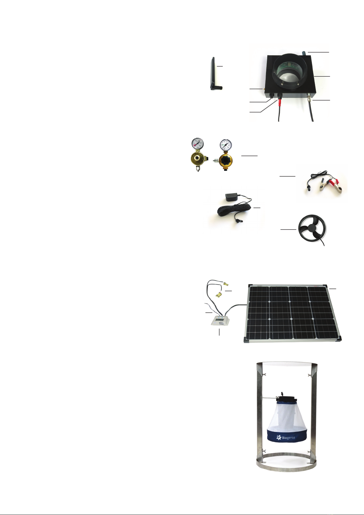
1. BG-Counter
1.1. Body
1.2. External antenna (female SMA connector)
1.3. Antenna connector
1.4. 12 V power connector
1.5. Fan connector (red) with attached fan adapter cable
1.6. CO2input port with attached CO2tube
1.7. CO2release port
1.8. Pressure regulator, two versions:
a) preset regulator
b) adjustable regulator
1.9. Battery adapter cable
1.10. AC power cord with transformer
1.11. BG-Counter fan: 3-blade, 12 V
2. Solar system
2.1. Solar panel with connectors
2.2. Solar controller with connectors
2.3. Battery cable, already connected to solar controller
2.4. Load adapter cable
3. BG-Trap Station
3.1. Parts of the BG-Pro trap (without fan)
3.2. Metal stand with bottom ring, lid, 2 beams, screws
and nuts
Product Components
1.9
1.3.
1.4
1.7
1.8
3.1
3.2
1.1
1.5
1.6
1.10
2.1
2.2
2.3
2.4
1.2.
a) b)
1.11
5EN
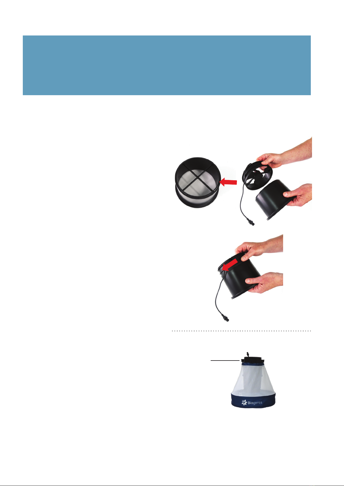
1.1
How to Set-Up the BG-Counter with the BG-Trap Station (recommended)
1. Assemble BG-Pro parts
Attach the enclosed BG-Counter 12 V fan (see page 4,
1.11) to the lower part of the inner cylinder of the BG-
Pro [F1]. Turn it clockwise until it ts tight [F2].
Then, follow assembly instructions for the BG-Pro. See
manual at www.biogents.com, but do not place the fun-
nel into the opening on top of the cover [F3]. The BG-
Counter will be placed here later on.
F3
Central upper bracket
Info
The BG-Counter runs on 12 V.
When using the BG-Counter with a BG-Trap Station or BG-Pro, always use the
12 V BG-Counter fan included in the BG-Counter contents (see page 4, 1.11).
F2
F1
6EN
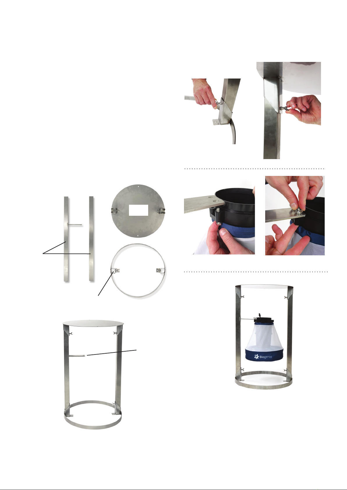
Beams
Bottom ring
Lid
Clamp
2. Assemble stand
Assemble the stand by placing the beams on both sides
in the clamps of the bottom ring and xing them with the
enclosed nuts [F4]. Place the lid clamps into the other
ends of the beams and also x them with nuts [F5].
3. Set up the BG-Pro in the stand: Insert an enclosed
screw through one of the holes on the central upper
bracket of the BG-Pro. Continue to insert the screw
through one of the holes of the trap holder of the
BG-Trap station [F6] and x it with a nut. Repeat this
process with another screw and the second hole [F7].
The BG-Pro should now be rmly attached to the BG-
Trap station [F8].
F7
F5
F4
F6
Trap holder
F8

7EN
F9, optional
F12
F10
F13
4. For routine operation of the counter, it is recommended
to not install a catch bag.
A catch bag and funnel net can be installed when the
trap and BG-Counter are run overnight or for a few
hours, and the catch is to be preserved for inspection:
Attach funnel net and catch bag to the bottom part of
the BG-Counter (if desired) [F9]. The funnel net is im-
portant to avoid double counts of insects crawling out.
For more information about this topic see chapter “De-
termination of Counting Accuracy”.
5. Fix the antenna on the BG-Counter: Place the BG-Coun-
ter on a at surface with the antenna connector facing
up (see Fig F10). Screw on the antenna, turning in a
clockwise motion until rmly attached. Do not overtigh-
ten the screw.
6. Place the BG-Counter into the opening on top of the
trap [F11] and turn it clockwise until it ts tight. Turn the
antenna to an upright position [F12].
7. Connecting the fan to the counter: Connect the red fan
adapter cable with the fan cable of the trap. Please pay
attention to always connect with the arrow in line with
the black marking line [F13].
F11
F12
8EN
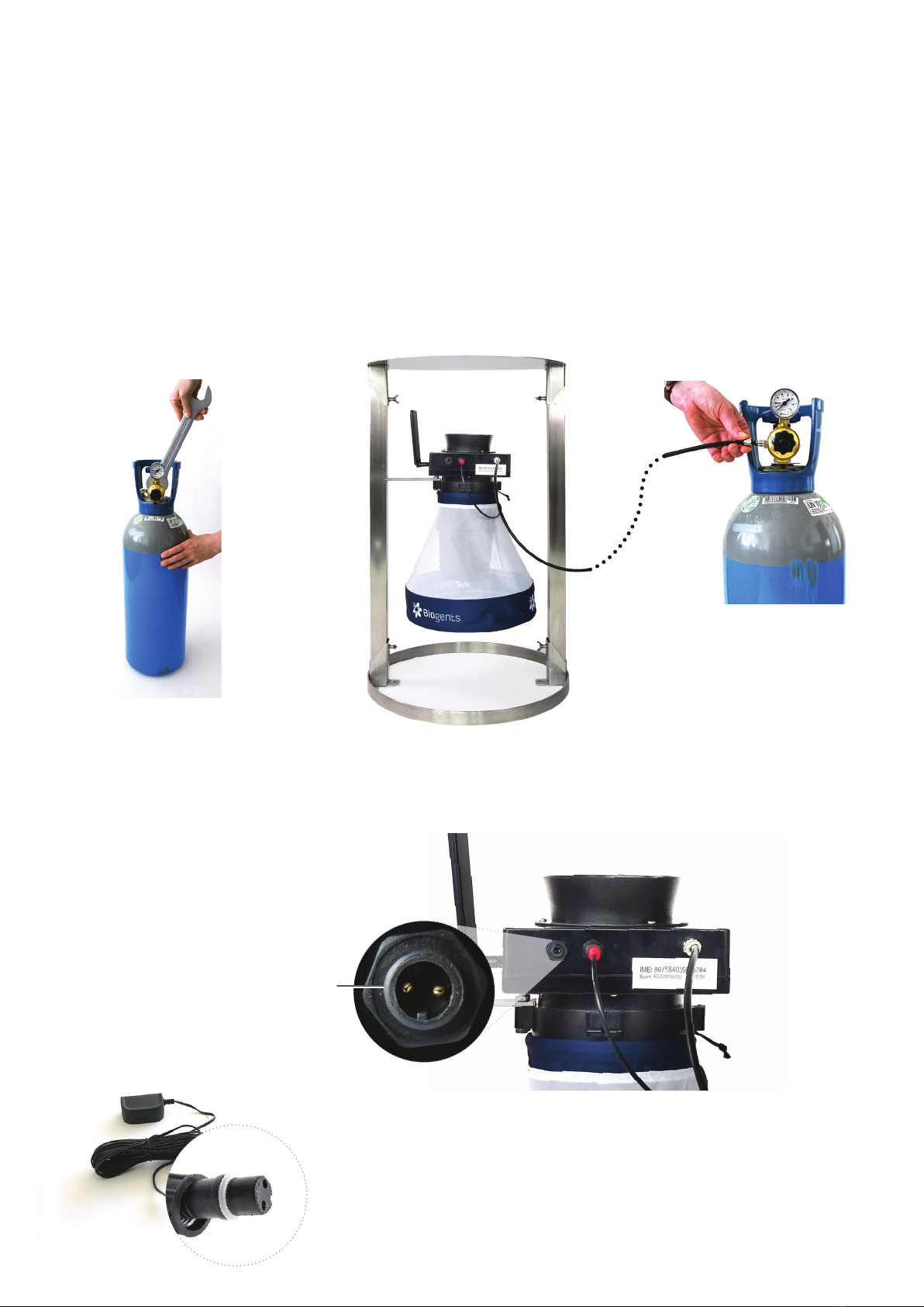
The CO2bottle is not included, and must be provided by the
user.
There exist two dierent versions of the pressure regulator:
a) The preset regulator is adjusted to 2.0 bar and the outlet
pressure cannot be changed.
b) The adjustable pressure regulator must be set at 1.5 kg/
day (corresponding to 2.6 bar). Therefore, adjust pressure to
mark “C” on the dial.
The ttings of the regulators are either US CGA-320 or Euro-
pe W21.8x1/14 RH standards.
Connect CO2
F15F14
1. Install the CO2pressure regulator on tank and make sure
it is tight by using a wrench or pliers [F14].
2. Connect the free end of the CO2tubing to the regulator
[F15]: unscrew the nut on the outlet, thread the end of
the CO2tube through the nut, insert the end of the CO2
tube rmly onto the outlet and re-screw the nut back
onto the outlet.
3. Now open the valve on the top of the CO2bottle to start
the release of CO2.
Option 1
Power cord with transformer
This is recommended if AC power is available at the counter location.
• Use only the provided AC adapter, and conrm local outlet style before
ordering:
• US: Nema 1-15
• Europe: CEE 7
Connecting the BG-Counter to Power: 3 Options
3 options to connect the
BG-Counter to power via
the 12 V power connection
9EN
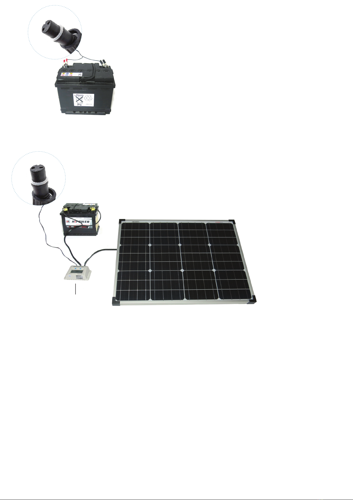
Option 2
12 V battery (provided by user)
This is recommended if the counter is operated in a location for a few days,
before being serviced or moved. The minimum number of hours of operation
possible with a full battery can be calculated as follows:
Operation hours = Battery capacity (Ah) x 2.
For example, with a battery capacity of 60 Ah (Ampere hours), the counter and
fan can be operated for at least 60 x 2 = 120 hours = 5 full days.
Use “deep cycle” lead-acid, or lithium-ion batteries. Normal car batteries are not
designed for continuous charge/discharge cycling, and thus would have signi-
cantly reduced lifetime.
• Connect battery using battery cable
Option 3
Solar panel with solar battery
This is recommended when the system needs to be operated autonomously for extended periods of time.
While the trap/Counter are usually placed in a shady location, the solar panel should be placed in a sunny
spot nearby; the solar controller and battery should be placed near the counter.
Solar controller
F16.1
F16.2
F16.3
Determination of Counting Accuracy
For routine operation, it is not recommended to use a catch
bag as the catch bag might be lled up too quickly. In this
way mosquitoes will be sucked through the ventilator and
end up dead at the bottom of the trap.
However, a catch bag can be installed when the BG-Counter
runs only for a few hours in order to check if the number
of counted mosquitoes by the BG-Counter corresponds
with the actual number of collected mosquitoes. In this way
the accuracy of the BG-Counter can be determined. When
comparing manual catch bag counts to electronic counts, it
should be noted that mosquitoes can “disappear” from the
catch bag:
Mosquitoes and other insects may be “stolen” by ants, spi-
ders, or geckos. For all calibration experiments make sure
that ants or other predators have no access to the catch bag.
You can protect the trap and catch bag by a water surface
around the trap, or by adding glue or PTFE to all trap parts
that might be accessible for predators.
If you make sure that mosquitoes do not leave the catch bag
after they have been sucked in the accuracy of the BG-Coun-
ter for correctly counted mosquitoes is between 80% and
90% correctly counted mosquitoes. If desired, experiments
can be performed from time to time to compare the catch
bag results with the electronic results reported for the same
time interval.
• Solar panel and solar controller are deliverd already connected [F16.1].
• Connect battery clamps to the battery (battery cables are delivered already con-
nected to the solar controller) [F16.2]. Pay attention to connect minus-pole to
minus-pole (black) and plus-pole to plus-pole (red).
• Connect the load cable to the BG-Counter [F16.3]

10 EN
1. Automatic start-up
The BG-Counter has no on/o switch or other buttons.
It automatically starts when connected to 12 V power.
2. Battery check
After the counter is connected to power, there will be from 1
to 4 beeps, depending on battery voltage.
• 4 beeps mean the battery is suciently charged
• If only 1-3 beeps are heard, this means the battery is low
and needs charging, and counting function, fan, and CO2
will be o until the voltage increases to >11.8V
• If there is no beep at all, see chapter Troubleshooting /
Trap does not start up
3. Cellular connection check
Following the battery check, the device proceeds to check
the strength of the cellular connection. This usually takes
less than 30 seconds, but may take several minutes, for ex-
ample, if the counter has been moved to a new location with
a dierent cellular provider.
At the end of the check, the counter indicates signal strength
as follows:
• 1-5 long beeps: corresponding to 1-5 bars of signal
• 2 short beeps: no signal, no cellular connection possible
Operating the BG-Counter
If no cellular connection is available, the counter can still be
operated. Data will be stored internally, and transmitted the
next time a connection is available.
4. Fan and CO2 ow check
After powering up, the fan and CO2valve are switched on
until the next round 15-minute interval (for example, if pow-
ered up at 16:03 until 16:15). This provides time for the ope-
rator to conrm that the BG-Pro 12 V fan is, indeed, working,
and the CO2 ow is on.
Conrm fan operation visually by looking into the trap fun-
nel, or by holding a piece of tissue paper above the funnel.
By default, the CO2 ow is adjusted to 50 g/h. The CO2dosing
valve is located inside the counter housing. It briey turns
on and o every 4 seconds.
Check for the presence of CO2 ow as follows:
• CO2tank valve open
• audible click from the valve
• hiss from the CO2release port
5. Counter check
If desired, the function of the counter can be veried at this
time by throwing a small object (for example, a small piece of
paper) into the trap funnel. A short beep is heard, indicating
the counter has registered the object.
The rst connection to the Cloud (http://www.bg-counter.
com) takes place at the rst round 15 minutes after the coun-
ter is started (for example, 16:15).
When connecting to the cloud, results are uploaded, and the
schedule dened on the web site is downloaded and acti-
vated.
First Cloud Connection
Reset
The BG-Counter is reset every time the power is disconnected and re-connected, and the start-up sequence commences as
described above.
Depending on the schedule, fan, CO2and/or counting
function may be turned o at this time.
If this is a new counter, the rst connection also auto-registers
the counter on the website.
Maintenance
Check the BG-Counter and trap bi-weekly or once a month for functionality, remove everything that deters mosquitoes from
entering the trap such as spider webs, leaves and any dirt.

11EN
The web application allows you to remotely switch traps in
the eld on and o. It also allows you to set up varying time
schedules to run the traps and to set up application times
of attractants. Further you have access to all collected data
including local environmental data such as temperature, hu-
midity, or light.
BG-Counter Website Description
On the website and in these instructions, the word “trap” re-
fers to a complete system including a trap and a counter.
The website address is live.bg-counter.com. Any modern web
browser (PC, tablet, or mobile phone) can be used to access
the website.
No registration is necessary to view the traps in the “Demo”
account.
To take advantage of the full functionality of the website,
you must rst be registered.
Registration for the Administrator (there is only one Admi-
nistrator for each organization):
• go to live.bg-counter.com and click on „Register“
• enter your e-mail address
• re-enter your e-mail address to make sure it’s correct
• enter the serial number of the counter (IMEI, located on
a sticker on the bottom of the counter): select from the
left hand side (1) the number that ts to the rst digits
of your serial number. Then add the last 7 digits in the
right eld.
Registration at live.bg-counter.com
You will receive a conrmation e-mail (please have also a
look for the e-mail in your spam folder) with a temporary
password and a link to activate your account.
Now you are a registered Administrator.
Log-in:
To check and control the counter, go to live.bg-counter.com:
• log-in with your e-mail address and your temporary pass-
word
• click on “Prole” to set a new password for your account
• set a checkmark in the box “Notify me about warnings”
if you want to be notied via e-mail if warnings are re-
gistered
• click on “Trap Management” to set the counter name,
schedule etc
• click on “User Management” to invite other users, such as
operators and guests
If you have more than one counter, you can add them to your
account in “Trap Management”.
1
12 EN
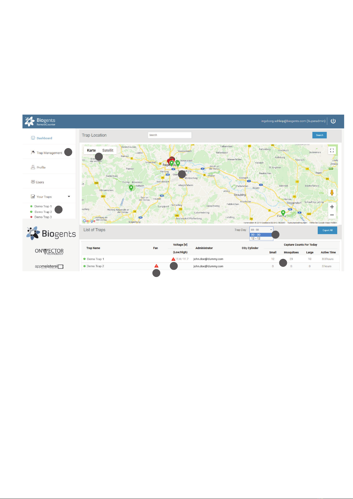
Once logged-in, the dashboard shows an overview over your traps in a map (2). When managing multiple traps, the location
display is convenient to conrm which trap is located where. That location is displayed using a label in Google Maps. You can
zoom in and out, and switch between a map display and a satellite image (3).
Active traps are shown in green, and inactive traps are shown in red.
Any devices with warning status are displayed on top of the list. Warning indicate low fan current (5) or low and high supply
voltage (6). More information on the dashboard warnings can be found on page 19 in the “Troubleshooting” section.
The traps are listed below the map in a short overview with daily captures (4).
Dashboard
• Administrators can view all traps belonging to their organisation
• Guests and operators can only see assigned traps
Viewing a trap and schedule CO2, fan and counter:
For each trap there is an own page with more details and the possibility to set a timer for CO2release and fan and counter
operation. Before you select a trap, select how you would like to have the trap day displayed on the trap page:
2
3
8
9
4
7
5
6

13EN
Main Menu
Beside the dashboard you nd following topics in the main menu (8):
Users (“Administrator” and “Operator” only)
• Allows to invite and delete users
Your Traps
• Provides shortcuts to the available traps (9)
Trap Management
• Provides a list of traps with serial number information
and links for viewing and controlling traps
Prole
• Allows a user to change passwords
There are several convenient ways to access a trap page:
• In the “Dashboard”, click on a trap name either in the map or in the list below the map
• In “Your Traps” (main menu left side), click on a trap name
• In “Trap Management” (main menu left side), click on a trap name or click on “View”
In the eld “Trap Day” (7) you can choose the range of the x-axis (time axis) for data visualization:
either “00-00” or “12-12”. In the rst case, data are shown from midnight to midnight, in the second case, data are shown from
mid-day to mid-day. The latter way of data exhibition might be more convenient, if you are interested in the dynamics of night-
active mosquitoes. The chosen time window will apply to all traps of your list.
Above an example for data visualization from 00:00-00:00 (= 00:00-24:00)
00:00
24:00

14 EN
How to assign BG-Counters to the dierent users:
Assignment to a new “Operator” (“Administrator” and
“Operator” only)
• Click on “Users”
• Fill out the form for inviting a new operator: Enter the
e-mail address, choose „Operator“ in the Role eld, and
write - if you wish - a comment for the new user.
• Choose the BG-Counters the operator can view and
control
• Click the “Invite” button
Assignment to a new “Monitor” (“Administrator” only)
• Click on “Users”
• Fill out the form for inviting a new monitor: Enter the e-
mail address, choose „Monitor“ in the Role eld, and write
- if you wish - a comment for the new user.
• Click the “Invite” button
Assignment to a new “Guest” (“Administrator” and “Opera-
tor” only)
• Click on “Users”
• Fill out the form for inviting a new guest: Enter the e-mail
address, choose „Guest“ in the Role eld, and write - if
you wish - a comment for the new user.
• Choose the BG-Counters the guest can view
• Click the “Invite” button
Assignment and Adding Additional BG-Counters
Assigning a BG-Counter to an existing “Operator” or “Guest”
(“Administrator” and “Operator” only)
You have two possibilities to do this:
First possibility
• Click on “Trap Management”
• Find the BG-Counter to be assigned, and click on “Users”
• In the “Assign Trap to User” screen, select an operator or
guest from the drop-down list
• Click “Assign”
Second possibility
• Click on “Users”
• Find the operator or guest to whom you want to assign a
trap
• Click on the blue button “Traps”
• In the “Assign Trap to User” screen choose the trap in the
drop-down list
• Click the “Assign” button
Administration Roles and Rights
We have four types of users:
“Administrator”
• Registers BG-Counters
• Can view and control the registered BG-Counters
• Can appoint operators and/or guest
• Can delete operators and guests
• Can assign BG-Counters to operators and guests
• Can remove BG-Counters from operators and guests
“Operator”
• Can view and control the BG-Counters assigned to him/
her
• Can appoint operators and/or guest
• Can delete operators and guests
• Can assign his BG-Counters to operators and guests
• Can remove his BG-Counters from operators and guests
“Monitor”
• Can view but not control all devices in an account;
multiple accounts can share a monitor user
“Guest”
• Can only view (but not control) assigned BG-Counters.
How to add additional BG-Counters (“Administrator” only):
• In “Trap Management”, click on the “Add Trap” button.
• Enter a name for the BG-Counter
• Enter the IMEI (International Mobile Equipment Identity).
The IMEI is printed on a sticker on the bottom of the coun-
ter module.
• Click on “Create”

15EN
After selecting and clicking a trap, the trap page is shown. Here you nd all of the data belonging to the trap inclusive capture
data. Further you can set a timer for CO2release and fan and counter operation.
Trap Location
On top of the trap page the trap location is shown in a Google map. When rolling over the marker with the mouse, the name
of the trap is shown:
Types of coordinates
Location is normally determined using the build-in GPS.
With “zoom in“ the circle will get visible:
GPS Location: Green circle, accuracy about 50 m (10). The
counter must be outdoors for GPS location to work.
Setting “Exact” coordinates
Since mosquito counts are strongly correlated with exact
trap location (down to the nearest bush perhaps), it is possi-
ble to use Google Maps to set the exact location of the trap.
Click on the pencil icon next to “Trap Location” (11). Now, an
arrow is shown below the trap label which points to the exact
location. Click and drag the label to the desired location,
zooming in and switching between map and satellite view
as required. The location is saved when clicking on an item
outside the map.
Default location
If a newly registered trap has not yet transmitted a location
signal, the location displayed will be either the last known
location (which can be some distance away from the present
location) or the location of the prime meridian in Greenwich,
UK.
The location displayed is the last known location. For histo-
ric data, the best estimate of the location on the day selected
in the main chart is shown.
Trap Page
11
10
16 EN
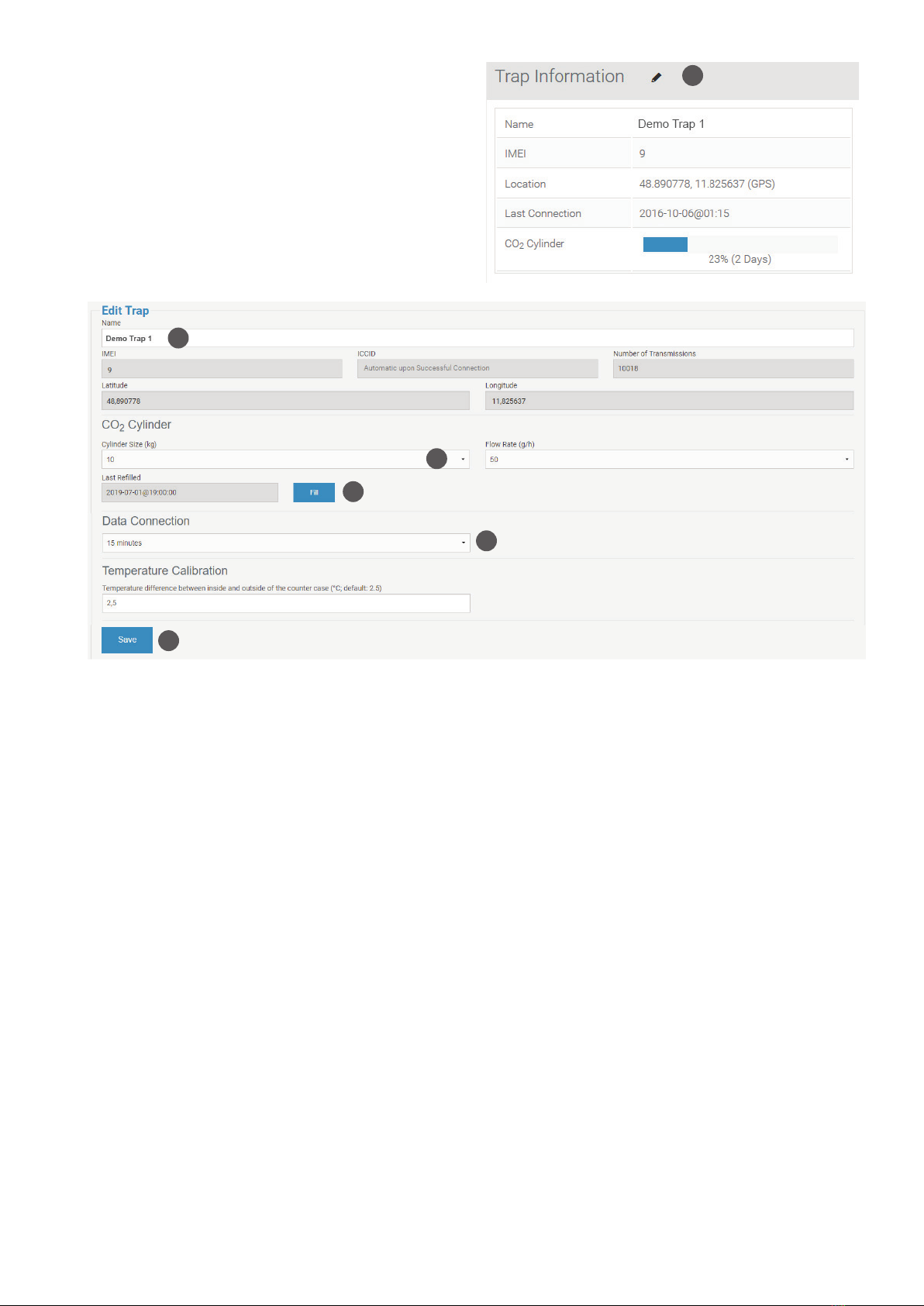
Trap Information
The trap information in the right box provides general data
to your trap like name, IMEI (International Mobile Equipment
Identity), last connection, and level of CO2cylinder.
For changing these data, click on the pencil icon next to the
“Trap Information” (12).
Name
To change, click on the text eld, and enter the new name
(13).
CO2cylinder
On the main trap page, an estimate is provided for the cur-
rent ll status of the CO2cylinder, and the time left until em-
pty. For the estimate to be correct, it is necessary to have a
xed schedule, and to indicate when the cylinder was last
lled.
Cylinder size (kg)
Click on “Please select” or the current size, and pick a size
from the drop-down list (14).
Fill
Click on the “Fill” button, and then select the date and time
at which the cylinder was last lled (15).
Flow rate
The ow rate is automatically set to 50 g/h. This is the opti-
mum number for operation of the BG-Counter to attract mos-
quitoes while at the same time repelling other insects. This
eld cannot be edited.
Data connection
Determines how often the counter will try to connect to the
website, and transmit counts and other data (16). The default
is every 15 minutes. Other choices are every 1, 2, 4, and
8 hours (Independent of this setting, count data are always
stored with 15-minute resolution).
The 15-minute setting is useful for diagnostics when the
counter is rst set up. However, during each transmission,
counting stops for 15-120 seconds, depending on the cellu-
lar signal strength. This can result in a small undercounting
error. In order to minimize this error, a data connection peri-
od of 1 hour or longer is recommended for routine operation.
A new setting is transmitted at the next data connection, i.e.
if previously the interval was set to 4 hours, and now an in-
terval of 1 hour is desired, it may take up to 4 hours until the
new setting is transmitted.
Save
Click on “Save” to save any changes that were made (17), or
click on your browser’s back button to return to the previous
page without saving the changes.
12
13
14
15
16
17

17EN
Trap Schedule
20
The trap schedule is used to control the operation of the trap: Here you can set a timer for the CO2release and the operation
of the fan and the counter. For each 15-minute interval during a day, the on/o status can be selected for the following:
• CO2: green = on, white = o.
• Fan: blue = on, white = o.
• Counter: orange = on, white =o.
To change the schedule, click on the pencil icon next to “Trap
Schedule” (18).
These elds can be set independently, although normally
they are all on at the same time. However, if for example a
catch bag is installed, and the catch is to be retained for coll-
ection, leave the fan on continuously.
Normally, the schedule is set to repeat daily; however, it can
also be set dierently for every day of the week (19).
18
Clicking and dragging changes the status (click on the circle
with a question mark for a short demo (20)).
Click on “Save” to save the new schedule, or click on your
browser’s back button to return to the previous page without
changing the schedule.
A new schedule is downloaded to the trap, and becomes
eective at the time of the next data connection (see Data
Connection in the “Trap Information“).
Edit the trap schedule:
19
18 EN
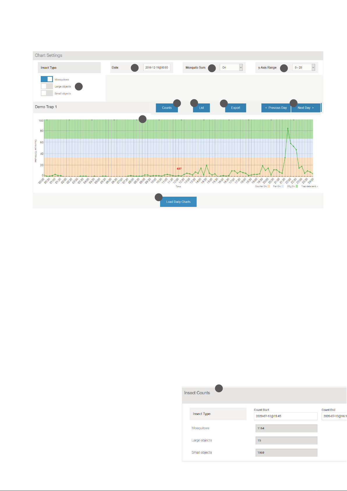
Chart settings
Here you can view the captures of your trap.
Exporting data into Excel
Clicking on the Export button brings up the “Export Data”
window (28). Here you can select a date range for export,
whether data are exported from 0-24 hours or 12-12 hours,
and the format of the export le (EXCEL or CSV, comma-se-
parated values.)
Daily charts
Scroll down below today’s chart, and click on “Load Daily
Charts” to display small charts for the last 30 days (29). This
is a convenient way to spot trends.
Note: Since a large amount of data is searched, it may take
up to 20 seconds or more to update the display.
Insect counts
Clicking on the “Counts” button (30) opens the “Insect
Counts” window (31) under the main chart. Here you can
specify a time frame (with start and end date and time), du-
ring which the numbers of collected mosquitoes, large ob-
jects, and small objects will be listed. This selection does not
aect the main chart.
Accessing historical data
Data are stored and presented for 15-minute intervals. All
times are local time at the last known location of the trap.
Chart settings
In Chart Settings, you can select for display:
• Insect Types (Mosquitoes, Large Objects, Small Objects)
(21): Press the „Insect Types“ button to see and select your
choice of insect types that will be shown in the chart.
• Date (22)
• Mosquito Sum (sum of counts for periods during which the
counter is on) (23)
• y-Axis range (24)
Main chart
When a trap is called up, today’s data are shown in the main
chart. Click on “< Previous Day”> or >“Next Day >” to navi-
gate day-by-day (25).
Color bars across the chart indicate the times during which
CO2, fan and counter, respectively, were turned on.
Small grey circles on top of the chart indicate the times at
which data connections took place (26).
Clicking on the chart displays the counts for the nearest
15-minute interval.
List
Click on “List” to see trap counts as well as status data dis-
played below the main chart (27). If the battery voltage is
getting low, it can be seen here. Also, the cellular reception
level is indicated; numbers of -113…-100 dB indicate a weak
signal, and data transmissions may become irregular.
21
22 23 24
26
29
25
27 28
30
31

19EN
Dashboard Warnings
When you log in, you will be presented with a dashboard
with a list showing the status of all BG-Counters in your ac-
count. Any devices with warning status are displayed on top
of the list. The following warnings are indicated with a red
triangle:
Fan column:
A triangle here means one of two conditions have been
detected:
1.) The fan current is low, indicating the fan is not running
even though it is turned on
2.) The fan current is high, indicating a stall (i.e. something is
blocking the fan blades)
Corrective action: Check the fan for proper operation.
Voltage Column:
The low and high supply voltage for the last 24 hours are
displayed.
A triangle here means that the lowest voltage is less than
11.5V, indicating a discharged battery or a solar system that
is not charging properly. The counter will be turned o when
the voltage drops to less than 11.2V in order to protect the
electronics. Once turned o, the counter remains turned o
until the voltage builds up again to 11.8V.
Corrective action may include one or more of the following:
• Charge the battery
• Use a battery with higher capacity
• Make sure solar panels are in full sun
• Check connections on solar controller
• Check solar controller for proper function
You can choose to be notied with an e-mail if warnings are
present. In order to turn on Notications, click on Prole,
then click on Notify me about warnings and click Save.
Trap does not start up
Symptoms:
• No beeps after connecting power
• Fan not working
• CO2valve not clicking
• A blue glow may be visible when looking into the counter
funnel
Cause: No power or wrong polarity
Solution: Check voltage, continuity, and polarity on the po-
wer connection.
Only one or two beeps upon start-up
Symptoms: Counter, fan and CO2 valve are o. No data
transmission.
Cause: Battery is too low.
Solution: Recharge battery, or replace with full battery.
SOS beep during start-up
Symptom: 3 short, 3 long, 3 short beeps
Cause: SD card failure
Solution: Contact support
Checking cellular connectivity
If the counter is in a location with weak cellular signal, the
cellular data connection to the server may be unreliable.
The signal strength at the deployment site can be checked
as follows:
Connect counter to power, then listen for beeps
1.) Immediately: One to four beeps indicating battery vol-
tage
4 beeps: fully charged
3 beeps: partially charged
2 or 1 beep: discharged, counter and trap will not run
2.) After 10-90 seconds, 1-5 long beeps indicating cellular
signal strength (like the bars on a cell phone)
3-5 beeps: strong signal
2 beeps: marginal signal
1 beep: weak signal
Two short beeps: no connection
Cellular signal too low
Symptoms: Two short beeps about 1-2 minutes after con-
necting the trap to power.
Cause: Weak or no cellular reception at the present location
of trap.
Solutions:
• Move trap to a location which has stronger reception
• Continue using the trap: data will be saved and uploaded
upon the next time there is reception
• If the cellular signal is very small in a remote location, the
following antennas may provide improvement. They can
be ordered directly from the suppliers listed.
1.) Advantech AO-AGSM-MG9S
Magnetic Mount
Includes 3.5m cable with SMA connector (directly ts BG-
Counter antenna connection)
https://www.mouser.com/ProductDetail/Advantech/AO-
AGSM-MG9S?qs=sGAEpiMZZMuBTKBKvsBmlN73K%2F2B
cYXlxNBf4MnSdn03UqYJSeMj4A%3D%3D
2.) Taoglas OMB.8912.03F21
Wall/Pole Mount
Female N-type connector
https://www.mouser.com/ProductDetail/Taoglas/OMB89
1203F21?qs=sGAEpiMZZMuBTKBKvsBmlIvfvst9g9R40Frl
fwg%252BLe8sulGjmpHLMA%3D%3D
Requires separate adapter cable (N-type plug to SMA
male), to be ordered in the needed length, for example:
https://www.amazon.com/Low-Loss-Extension-
Connector-GEMEK-Arrester/dp/B07P12XW3J/
ref=sr_1_4?keywords=n-type+to+sma+cable&qid=1562
655621&s=gateway&sr=8-4
Troubleshooting

20 EN
Troubleshooting
Cellular transmission stops
Symptom: Counter stops transmitting data even though cel-
lular signal strength is good.
Cause 1: Extremely low battery (<11.2 V). To protect the
counter from damage, the electronics, fan and CO2are shut
down. In order to view the last transmitted battery voltage,
go to the the trap page and press the “List” button.
Note: A 12 V battery is considered 0 % charged when the
voltage is below 11.8 V.
Solution: Replace or charge battery.
Cause 2: Counter needs reset
Solution:
• Disconnect power
• Wait 30 seconds
• Reconnect power
• Insert hand into funnel to block insect sensor
• Verify 4 beeps for power
• After 15-90 seconds, verify cellular signal strength (3-5
long beeps)
• After verifying cellular signal strength, there will be about 5
additional short beeps followed by a long beep.
• After 30 minutes, go to the web site and see if there are
new transmission
Irregular transmission times
Symptoms:
• Trap doesn’t transmit data when scheduled
• Irregular spacing of connection circles in main chart
Cause: Weak cellular connection or cellular network busy.
Solution: See „Cellular signal too low“
Solar battery voltage gradually drops
Symptom: When viewing “List” data, it is observed that the
solar battery is not maintaining voltage. Eventually, counting
and transmission of data stops.
Cause: Not enough sunlight to keep solar battery charged.
Solutions:
• Modify schedule to only measure during peak hours of
mosquito activity
• Move solar panel to a sunnier position
• In rare cases, a larger solar panel may be needed. Contact
Biogents
Table of contents
Other Biogents Cash Counter manuals


