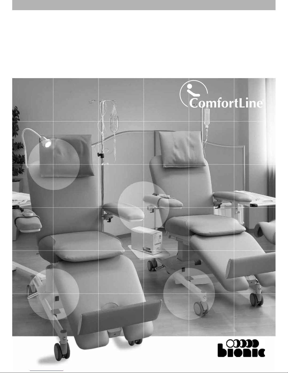
Bionic ComfortLine User manual
GEBRAUCHSANWEISUNG
INSTRUCTIONS FOR USE
MODE D‘EMPLOI
www.therapychair.com


Inhaltsverzeichnis
A. Auspacken 1
B. Zusammenbau 1
C. Hinweise für den Gebrauch 3
D. Wartung, Prüfung, Pflege 11
E. Typenschild 12
F. Entsorgung 13
G. Fehlersuche 14
H. Technische Daten 16
Table of content
A. Unpacking 1
B. Assembly 1
C. Instructions for handling 4
D. Maintenance, Inspection and Care 11
E. Type plate 12
F. Disposal 13
G. Troubleshooting 14
H. Technical data 16
Contenu
A. Déballage 1
B. Assemblage 1
C. Instructions de manipulation 3
D. Maintenance, inspection et entretien 10
E. Plaque signalétique 11
F. Disposition 13
G. Aide au diagnostic 14
H. Caractéristiques techniques 16

1
A. Auspacken
Palette nur mit Gabelstapler bewegen. Karton nicht auf-
schneiden.
▪Äußere Spannbänder entfernen
▪Karton-Schutzhaube abheben
▪Innere Spannbänder entfernen
▪Liege von der Palette abheben
Tragen Sie die Liege ausschießlich an den Flachovalrohren
des Grundgestells.
B. Zusammenbau
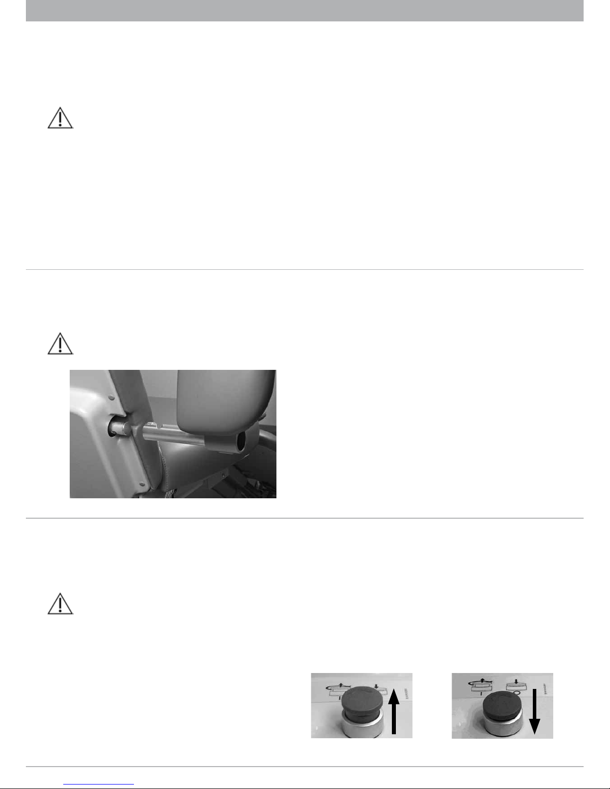
1. Transportsicherung entfernen
Transportsicherung und Kabelbinder vor Inbetriebnahme
entfernen! (Abb. / Fig. 1)
Nach dem die Transportsicherung und der Kabelbinder entfernt
wurden (Abb. / Fig. 2), das Schubrohr des Beinteilmotors mit der
Aufnahmelasche an der Unterseite des Beinteils verbinden und
mit dem Bolzen mit Sicherungsring fixieren. (Abb. / Fig. 3)
2. Einstecken des Kopfteils
Das Ovalrohr des Kopfteils wird in die dafür vorgesehene Öff-
nung auf der Rückseite des Rückenteils eingesteckt. Die Höhe
des Kopfteils ist variabel. Das Kopfteil wird nach der Einstellung
mit der Sternschraube fixiert.
Kabelbinder
Cable tie
Attache-câble
Transportsicherung
Transportsafety device
Sécurité de transport
Abb. / Fig. 1
A. Déballage
Utiliser un chariot élévateur, pour transporter la palette. Ne
pas découper le carton.
▪Enlever les courroies extérieures de la palette
▪Soulever le carton protecteur vers le haut et le retirer
▪Enlever les courroies internes qui fixent la chaise
▪Retirer la chaise de la palette
Porter la chaise seulement sur les tubes ovales-aplatis de la
trame de base.
B. Assemblage
1. Retirer la sécurité de transport
Retirer la sécurité de transport et l’attache-câbles avant
d‘utiliser! (Abb. / Fig. 1)
Après la sécurité de transport et l’attache-câbles sont retirés
(Abb. / Fig. 2), relier la tige du moteur de la partie jambes sur à
l’aide d’un gousset de réception puis la fixer avec l‘écrou. L’écrou
est sécurisé grâce à la bague de sécurité. (Abb. / Fig. 3)
2. Insérer l’appui-tête
Le tube ovale de l’appui-tête doit être inséré dans l’ouverture si-
tuée à l’arrière du dossier. La hauteur de l’appui-tête est réglable.
Pour régler à la hauteur désirée, il suffit de tourner la manivelle.
Abb. / Fig. 3
A. Unpacking
Use a forklift for transportation! Do not cut into the carton!
▪Remove outer straps from pallet
▪Lift carton and put it aside
▪Remove inner straps
▪Remove the chair from pallet base
Do only use the flat oval pipes of the base frame to carry the
chair.
B. Assembly
1. Remove transport safety device
Remove the transport safety device and cable tie before
using the chair! (Abb. / Fig. 1)
After the transportation safety device and the cable tie have been
removed (Abb. / Fig. 2), connect the push rod of the leg segment
motor with the receiving strap on the bottom side of the leg seg-
ment. Now fix rod and leg segment with the bolt and the circlip.
(Abb. / Fig. 3)
2. Inserting the head segment
Insert the oval tube of the head segment in the appropriate
aperture in the rear of the back segment. The height of the head
segment is variable. Choose the appropriate setting and then fix
the head segment with the screw.
Abb. / Fig. 2
2
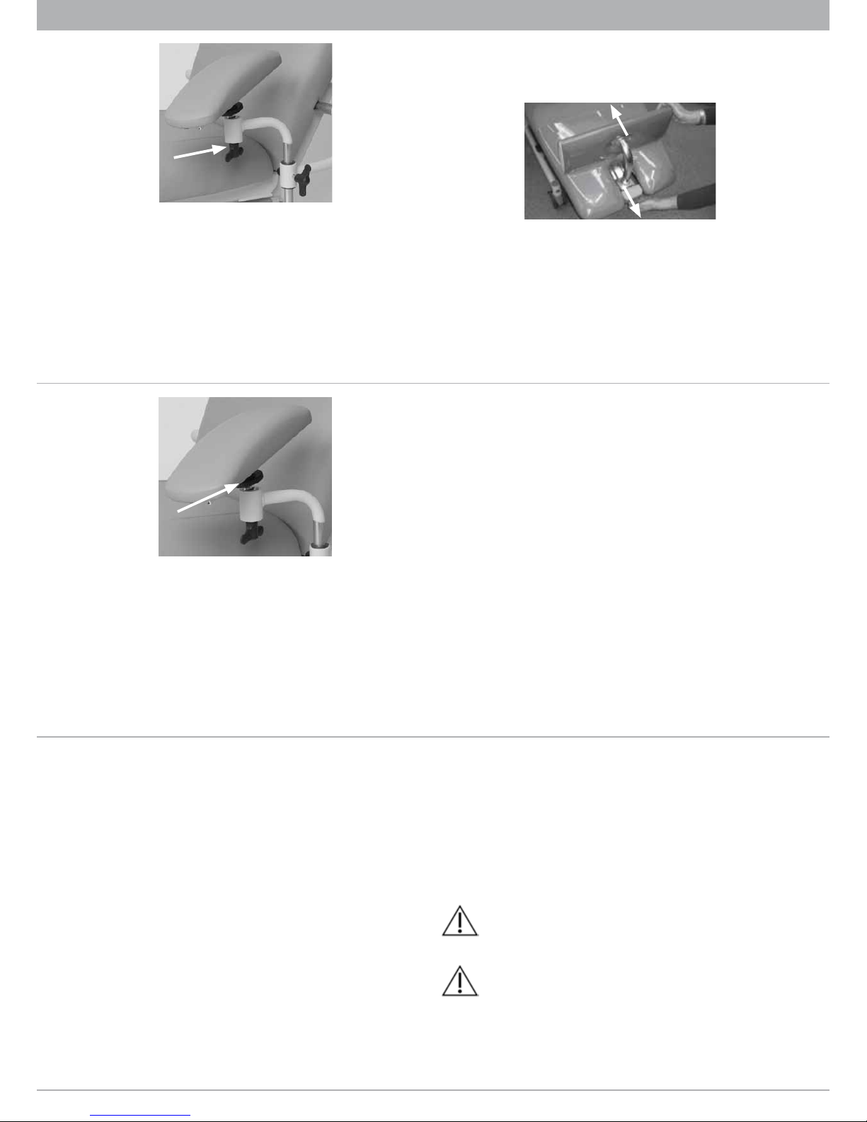
3. Einstecken der Armlehnen
Die Armlehnen werden auf die Rückenwelle aufgesteckt. Arm-
lehnen senkrecht halten und durch Verdrehen der Armlehne
mit einem leichten Gegendruck die Einrasterung des Bajonett-
Verschlusses suchen. (Abb. / Fig. 4) Nachdem die Armlehne ganz
auf die Rückenwelle eingeschoben ist, kann sie wie üblich nach
hinten weggeklappt werden.
Unbedingt prüfen, ob die Armlehne in waagrechter Position
sich nicht abziehen lässt. Unsachgemäßge Anbringung kann zur
Schädigung der Armlehne führen.
4. Elektrischer Anschluss
Die Liege an das Stromnetz anschließen.
Beachten Sie, dass das Netzkabel durch das Überfahren mit den
Rollen der Liege beschädigt werden kann. Um dies zu vermei-
den, ist vor dem Verfahren der Liege das Netzkabel aufzurollen
und im aufgerollten Zustand auf den Sitz zu legen oder über die
Armlehne einzuhängen.
Die ComfortLine mit Akku wird ausschließlich über den integ-
rierten Akku betrieben und verfügt nicht über ein Netzkabel.
5. Ein- und Ausschalter
Der Ein- und Ausschalter befindet sich auf der rechten Seite un-
ter der Sitzfläche in Höhe des Grundgestells. Bei Nichtgebrauch
sollte das Netzteil durch den Ein- und Ausschalter vom Strom-
kreis getrennt werden. Bitte vergewissern Sie sich nach dem
Ausschalten der Liege, dass alle Funktionen des Handschalters
gesperrt sind. (Abb. / Fig. 7)
Bei der ComfortLine mit Akku befindet sich der Ein- und Aus-
schalter direkt auf der Oberseite des Akkus. Zum Ausschalten
muss der rote Drehkopf einfach nach unten gedrückt werden.
Durch Drehen und Hochziehen des Schalters lässt sich die Liege
einschalten und alle Motoren sind wieder verstellbar.
(Abb. / Fig. 5 und Abb. / Fig. 6)
3. Inserting the armrests
Insert the armrests on the back shaft. Hold armrest in vertical po-
sition and turn the armrest with slight counter-pressure to achie-
ve locking by the slide catch. (Abb. / Fig. 4) Once the armrest is
fully inserted, it can be moved up- and backwards as desired.
Make sure that the armrest cannot be removed in horizontal
position. Improper mounting can damage the armrest.
Abb. / Fig. 4
4. Electrical outlet
Connect the therapy chair with the power supply system.
Passing over the power cord with casters should be avoided by
appropriate installation. To avoid any damage, the net cable has
to be rolled up before moving the chair and has to be laid on the
seat or hung up over the arm-rest in the rolled up condition.
The ComfortLine with rechargeable battery is only run by the
integrated rechargeable battery. Therefore it does not have any
power cord.
5. On/Off switch
The On/Off switch is located on the right side under the seat
surface at base structure level. The mains connection should be
switched off if the dialysis chair is not in use. After switching off
please ensure that all buttons of the remote control are locked.
(Abb. / Fig. 7)
The ComfortLine with rechargeable battery has the on/off switch
on the upper side of the rechargeable battery. To switch off the
therapy chair press the red rotating switch. By rotating and lifting
3. Insertion des accoudoirs
Les accoudoirs sont placés sur l‘axe arrière. Les accoudoirs sont
enfoncées verticalement et en tournant l’accoudoir avec une lé-
gère pression de la fermeture à baïonnette est demandée. (Abb.
/ Fig. 4) Ensuite l’accoudoir est complètement inséré, ils peuvent
se replier comme d‘habitude.
Assurez-vous que l‘accoudoir ne peut être retirée en position
horizontale. Un montage incorrect peut endommager l‘accoudoir.
4. Raccordement électrique
Raccorde la chaise au réseau électrique.
Évitez de rouler sur le câble d’alimentation avec la chaise pour
ne pas l’endommager. Afin d’éviter tout dommage, enroulez le
câble d’alimentation et le placer sur le siège ou le pendre aux
accoudoirs.
Le ComfortLine avec batterie marche seulement avec la batterie.
Il n‘ a pas un cordon secteur.
5. Commutateur Marche/Arrêt
Le commutateur Marche/Arrêt se trouve sur le côté droit sous le
siège au niveau de la base. Le câble d’alimentation devrait être
débranché lorsque la chaise de dialyse n’est pas utilisée. Après
avoir été mis en arrêt, assurez-vous que tous les boutons de la
commande manuelle sont barrés. (Abb. / Fig. 7)
Dans le cas du ComfortLine avec batterie, il ya le commutateur
Marche/Arrêt sur la face supérieure de la batterie rechargeable.
Pour désactiver le fauteuil presse le commutateur rotatif rouge.
En tournant et en soulevant le commutateur le ComfortLine avec
batterie est activé et les moteurs peuvent être exécutés.
(Abb. / Fig. 5 et Abb. / Fig. 6)
Abb. / Fig. 5 Abb. / Fig. 6

3
Abb. / Fig. 7
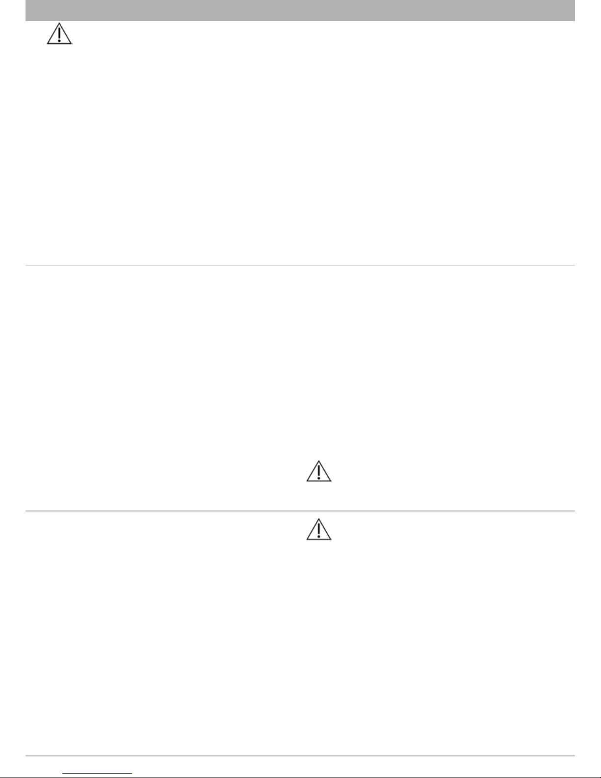
6. Einsetzen des Sitzteils
Das Sitzteil ist an der Unterseite mit Halteclips ausgestattet. Mit
diesen wird das Sitzteil in den dafür vorgesehenen Aufnahme-
bolzen am Rahmen fixiert, hierzu muss das Rückenteil zuvor
nach hinten gefahren werden. (Abb. / Fig. 8)
Bitte stellen Sie sicher, dass die Halteclips des Sitzteils in die
dafür vorgesehenen Bolzen eingerastet sind. Andernfalls kann sich
das Sitzteil verschieben.
7. Potentialausgleich
Die ComfortLine ist serienmäßig mit Potentialausgleich ausge-
stattet. Der Anschlussbolzen nach DIN 42801 befindet sich am
Grundgestell hinten rechts.
C. Hinweise für den Gebrauch
1. Allgemeines
Bionic Behandlungsliegen sind für die vorübergehende Lage-
rung von Patienten und Spendern unter medizinischer Aufsicht
bestimmt. Eine dauerhafte Lagerung ist nicht vorgesehen.
Bei Nutzung in der Röntgendiagnostik ist zu beachten, dass die
Liege nicht zur Durchleuchtung geeignet ist.
Für die Behandlung von körperlich oder psychisch behinderten
Menschen sollte die Verwendung vom medizinischen Fachperso-
nal beurteilt werden.
Die Behandlungsliege ist für normal große Patienten geeignet.
Durch Verlängerung des Kopfteils und/oder Ausfahren der Fuß-
stütze kann die Liege an die Körpergröße des Patienten ange-
passt werden. Um das Verletzungsrisiko zu minimieren, ist die
Liege im unbeaufsichtigten Zustand in die niedrigste Position zu
fahren.
the switch the ComfortLine with rechargeable battery becomes
activated and the motors can be run.
(Abb. / Fig. 5 and Abb. / Fig. 6)
6. Installing the seat section
Clamps are provided on the bottom side of the seat section.
Use these clamps to fix the seat section in the corresponding
recesses in the frame. Therefore it is necessary to adjust the back
segment backwards. (Abb. / Fig. 8)
Please make sure that the notches of the seat segment are lo-
cked and secured with the three notches on the corresponding bolts
of the seat frame. If not locked properly, the seat segment might
slide unintentionally.
7. Equipotential bonding
ComfortLine includes an equipotential bonding as standard. The
connection bolt according to the DIN 42801 standard is located
on the right back of the base frame. Abb. / Fig. 8
6. Installation du siège
Le siège est pourvu d’attaches (clips) situées en dessous. Servez-
vous de ces attaches pour fixer le siège à l’endroit prévu à cet
effet. Avant le dossier doit être déplacé à l‘arrière. (Abb. / Fig. 8)
S‘il vous plaît assurez que les clips de fixation de l‘assise sont
happés dans les boulons fournis. Sinon, le siège peut se déplacer.
7. Compensateur de potentiel
Le ComfortLine est équipé d’un compensateur de potentiel. Le
boulon de fixation, conformément à la norme DIN 42801 se trou-
ve sur la structure de base à l’arrière du côté droit.
C. Instructions de manipulation
1. Général
L’utilisation de la chaise Bionic est prévue pour un traitement
temporaire sous surveillance médicale.
Il n’est pas permis d’exposer la chaise à des fins de radiation ou
de rayons ultra-violets. En utilisant la chaise pour radiodiagnostic,
faire attention que c‘est opaque à la radiation.
La chaise ne rencontre probablement pas les besoins de gens
handicapés (spécialement mentals). En cas de doute, le person-
nel médical formé devra juger si la chaise peut être utilisée ou
non.
La chaise a été conçue pour les gens de tailles normales et peut
être ajustée selon la taille du patient entirant sur l’appui-tête et/
ou en ajustant le repose-pied. Quand la chaise n’est pas utili-
sée, elle devrait être placée à la plus basse position pour éviter
les risques de blessures en s’assoyant ou en débarquant de la
chaise.
Les utilisateurs doivent avoir reçu les instructions de manipu-
lation et doivent en connaitre les risques. Nous recommandons de
bien laisser à la vue les instructions pour tous les utilisateurs et de
s’assurer qu’elles ont été lues et bien comprises.
S’assurer que les mouvements de la chaise ne soient pas
restreints. Ex. : rebords de fenêtres, câbles d’alimentation, etc. Des
dommages pourraient survenir. (Abb. / Fig. 9)
4
Alle Nutzer der Liege sind durch den Betreiber in die Hand-
habung einzuweisen und auf die in dieser Gebrauchsanweisung
angemerkten Gefahrenpunkte aufmerksam zu machen. Wir emp-
fehlen dem Betreiber diese Gebrauchsanweisung den Anwendern
zugänglich zu machen und sich zu vergewissern, dass diese gelesen
und verstanden wurde.
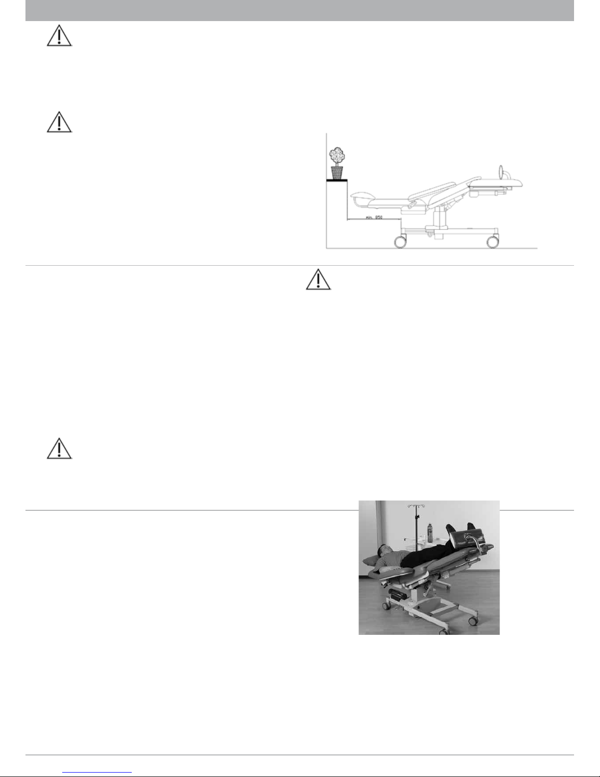
Bewegungsabläufe der Liege nicht durch bauliche Gegeben-
heiten, z. B. Fensterbänke oder Versorgungskanäle, behindern.
Beschädigung der Polster, Antriebe oder Gelenkverbindungen ist
möglich. (Abb. / Fig. 9)
Bei Nutzung der Liege in Kombination mit einem Beistelltisch
ist eine Höhenverstellung nur bei zurückgeschobenem Tisch
zulässig.
Die Unterfahrbarkeit der Liege beträgt 110 mm, im Falle der
ComfortLine mit Tiefeinstieg nur 30 mm.
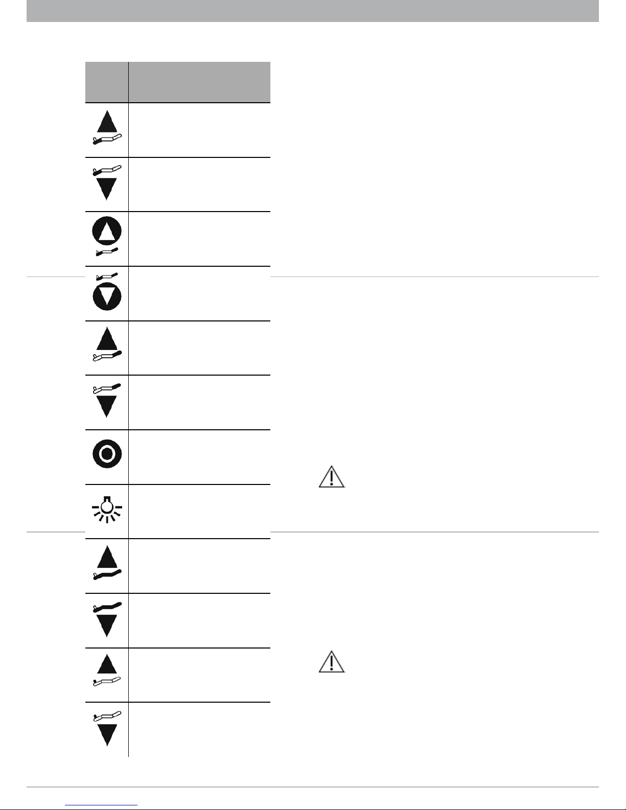
2. Funktion des Handschalters
Die ComfortLine verfügt zur Einstellung der Positionen über 5
Antriebe, die mittels Handschalter bedient werden. (Tabelle)
3. Schockposition
Die Schockposition wird über den Fußtaster im vorderen Teil des
Grundgestells erreicht. Hierbei werden die Motoren mit höherer
Geschwindigkeit gefahren, deshalb darf der Fußtaster nicht zur
normalen Verstellung der Liege benutzt werden. (Abb. / Fig. 10)
Abb. / Fig. 9
C. Instructions for handling
1. General
Intended use for Bionic therapy chairs is the temporary position
of patients or donors during treatment under medical supervisi-
on. By using the chair for x-ray diagnostics please consider that it
is opaque to radiation.
The chair does probably not meet the needs of (especially men-
tally) handicapped people. In case of doubts medically skilled
staff should judge whether the chair can be used or not.
The chair is designed for people of normal size. It can be adjus-
ted to the patient size by pulling out the head rest and/or adjus-
ting the footrest. When not using the chair it should be moved
into the lowest position to avoid the risk of injuries when getting
in or out of the chair.
All users of the chair, especially personnel, patients or
donors have to be instructed in the handling of the chair and have
to be made aware of the risks. We recommend to hand out this
instruction to all users and to make sure that it is read and well
understood.
Please make sure that movements of the chair are not restric-
ted by architectural facts i.e. window sills, maintenance cables etc.
Damage of the back segment motor or of the joints can occur. (Abb.
/ Fig. 9)
If the chair is used in combination with a table, height adjust-
ment may only be engaged when the table is removed.
The ground clearance of the chair is 110 mm, in case of Comfort-
Line with low entrance only 30 mm.
2. Functions of remote control
The ComfortLine is equipped with 5 motors for the adjustment
of the different position by hand switch. (Table)
3. Shock position
The shock position is set using the foot switch at the front of the
base structure. Therefore the motors work at higher speed and
this is why the foot pedal may not be used for normal adjustment
of the chair. (Abb. / Fig. 10)
Si la chaise est utilisée en combinaison avec une table,
l’ajustement de la hauteur de la chaise ne peut être engagé que
lorsque la table est enlevée.
S‘il vous plaît noter la garde au sol limitée de 110 mm, en cas de
ComfortLine à assise abaissée 30 mm.
2. Fonctions de la commande manuelle
Le Comfortline est équipé de 5 moteurs pour l‘ajustement de la
position différente par commande manuelle. (Tableau)
3. Position Trendelenburg / Position de choc
La position Trendelenburg est atteinte en appuyant sur la pédale
située sur la partie avant de la structure de base. Les moteurs
fonctionneront à une vitesse plus élevée et c’est pourquoi
l’utilisation de la pédale ne devrait pas être utilisée pour le
réglage normal de la chaise. (Abb. / Fig. 10)
Abb. / Fig. 10
4. Enlever des accoudoirs
De faciliter l‘entrée d‘un fauteuil roulant, les accoudoirs peuvent
être enlevés. En ComfortLine à assise abaissée il est aussi possib-
le d‘arrêter le fauteuil sur une hauteur d‘entrée de 50 cm.
Pour enlevé l’accoudoir doit être tourné en arrière. Après le
verrouillage de l‘accoudoir de la direction à la baïonnette, ils
peuvent être enlevé.
5
4. Abnehmen der Armlehnen
Um den Einstieg aus einem Rollstuhl in die Liege zu erleichtern,
können die Armlehnen abgenommen werden. Bei der Comfort-
Line mit Tiefeinstieg ist es hierbei zusätzlich möglich, die Liege
auf eine Einstiegshöhe von 50 cm herunterzufahren.
Hierzu wird die Armlehne mit einem leichten Zug nach hinten
geschwenkt. Nach Einrasten der Armlehne in die Bajonett-Füh-
rung kann sie von der Rückenwelle heruntergezogen werden.
5. Einstellen der Standard Armlehnen
Unter den Kugelgelenken am hinteren Ende der Armlehnen
befindet sich auf jeder Seite ein Feststeller. Nach Lösen des
Feststellers lassen sich die Armlehnen frei bewegen. In Grund-
stellung stehen beide Armlehnen im rechten Winkel zur Rücken-
lehne und parallel zur Sitzfläche. Um die eingestellte Position
zu fixieren, wird der Feststellhebel im Uhrzeigersinn mit mäßi-
ger Kraft festgezogen. Durch den Reibschluss im festgestellten
Kugelgelenk wird sich die Position der Armlehnen bei normaler
Gewichtsbelastung durch den Unterarm des Patienten nicht
verändern.
4. Removing the armrest
In order to facilitate the entrance from a wheelchair into the the-
rapy chair, the armrests can be removed. In case of ComfortLine
with low entrance it is possible to adjust the therapy chair to an
entrance height of 50 cm.
For this it is necessary to swing the armrest backwards to reach
the slide catch and the armrest can be pulled off the chair.
5. Adjustment of standard armrests
Underneath the ball and socket joints of each armrest is a locking
lever. In the unlocked setting, the armrest moves freely around
the ball for adjustment. Turn the armrest into the standard po-
sition in a right angle to the backrest and parallel to the sitting
area. For locking the desired position, the locking lever is to be
tightened clockwise with moderate force. The friction in the ball
and socket joint will easily hold the weight of the arm.
Do not move the armrest without releasing the locking lever.
If the locking lever is pulled downwards, it can be rotated freely
and adjusted to a parallel position. When pulled back by the re-
5. Ajustement des accoudoirs standard
Parmi le rotule de l‘accoudoir est situé de chaque côté un levier
de blocage. Après avoir ouvré le levier de blocage les accoudoirs
peuvent se déplacer librement. En position de base, les deux
accoudoirs sont à angle droit et parallèlement au dossier. Afin de
fixer la po-sition définie, le levier de blocage est serré avec une
force modérée. En raison de la friction dans la rotule, la position
de l’accoudoir ne changera pas si le charge d’avant-bras est nor-
mal.
L‘accoudoir ne devrait pas être modifié sans débloquer le
levier de blocage.
Si le levier de blocage est tiré an bas il peut être tourner sur l‘axe.
Il est rétracté automatiquement dans la position enclenché par
un ressort. Desserrer et fixer de la rotule est seulement possible
en position enclenché (Abb. / Fig. 11).
Le feuteuil est livré en standard avec un accoudoir rétractable li-
vré. Cette fonctionnalité permet d‘abaisser le accoudoir de la po-
Taste
Switch
Bouton
Funktion
Function
Fonction
Beinteil hoch
Leg segment up
Relèvement de la partie jambes
Beinteil tief
Leg segment down
Baissement de la partie jambes
Sitzneigung nach hinten
Seat inclination backwards
Relèvement d‘inclination du siège
Sitzneigung nach vorne
Seat inclination towards
Baissement d‘inclination du siège
Rückenteil hoch
Back segment up
Relèvement du dossier
Rückenteil tief
Back segment down
Baissement du dossier
Rückstellung in Sitzposition
Back to sitting position
Retour en position assise
Ein- und Ausschalter für Lampe (optional)
On/Off switch for lamp (optional)
Commutateur Marche/Arrêt pour lampe
(optionnel)
Sitzhöhe nach oben
Seat height up
Réglage en hauteur du siège
Sitzhöhe nach unten
Seat height down
Réglage de la hauteur du siège
vers
Fußstütze hoch
Foot rest up
Relèvement du repose-pied
Fußstütze tief
Footrest down
Abaissement du repose-pied

6
Verstellen Sie die Armlehne nicht ohne den Feststeller zu
lösen.
Der nach unten gezogene Feststellhebel lässt sich lose auf der
Achse verdrehen. Er wird durch eine Feder automatisch in die
eingerückte Stellung zurückgezogen. Lösen und Feststellen des
Kugelgelenkes ist nur in eingerückter Stellung möglich (Abb. /
Fig. 11).
Die Liege wird standardmäßig mit einer absenkbaren Armleh-
ne geliefert. Diese Funktion erlaubt es, die Armlehne aus der
waagrechten Position um 20° abzusenken. Um diese Funktion
zu ermöglichen, muss der Bolzen bei gelöstem Feststeller nach
außen geschoben werden und dann der Feststeller wieder fixiert
werden (Abb. / Fig. 12).
Vor der ersten Nutzung dieser Funktion muss die Schraube gelöst
und der Bolzen gelockert werden.
6. Einstellen der Transfusionsarmlehne (optional)
In Grundstellung stehen beide Armlehnen im rechten Winkel
zur Rückenlehne und parallel zur Sitzfläche.
Durch Lösen der ersten Feststellschraube lässt sich die Armlehne
frei bewegen.
Um die eingestellte Position zu fixieren, wird die Feststellschrau-
be im Uhrzeigersinn mit mäßiger Kraft festgezogen. Durch den
Reibschluss im festgestellten Kugelgelenk wird sich die Position
der Armlehnen bei normaler Gewichtsbelastung durch den Un-
terarm des Patienten nicht verändern (Abb. / Fig. 14).
Durch Lösen der Rändelschraube kann man die Armpolster nach
vorne und nach hinten verstellen. Sobald die gewünschte Posi-
tion eingestellt ist, wird mit der Rändelschraube diese Position
fixiert (Abb. / Fig. 14) .
Mit Lösen der zweiten Feststellschraube kann die Armlehne
in Höhe verstellt werden. Nachdem die gewünschte Position
eingestellt ist, kann diese durch Festziehen der Feststellschraube
fixiert werden (Abb. / Fig. 13).
lease spring, the lever is engaged with the screw for locking and
unlocking (Abb. / Fig. 11).
Abb. / Fig. 11
It is also possible to lower the armrest by approx. 20° from ho-
rizontal position. The chair is always delivered with armrests in
horizontal-blocked position. To loosen this fixation the bolt has
to be pulled outwards while the locking lever is released. After-
wards the locking lever should be fixed (Abb. / Fig. 12).
Before first use of this function the screw as well as the bolt have to
be loosened.
6. Adjustment of transfusion armrest (optional)
In the basic position both armrests are located parallel to the
seat.
By unscrewing the first locking screw the armrest can be moved
freely. In order to fix the adjusted position, tighten the locking
screw clockwise with moderate force. Because of the frictional
engagement in the determined ball joint the normal weight load
of the patient’s arm will not change the position of the armrest
(Abb. / Fig. 14).
The armrest upholstery can by adjusted forwards and backwards
by unscrewing the knurled knob. As the desired position is ad-
justed, this position can be fixed by tightening the knurled knob
(Abb. / Fig. 15).
The second locking screw is necessary to change the height of
the armrest. After the desired position is adjusted, it can be fixed
by tightening the locking screw (Abb. / Fig. 13).
sition horizontale de 20 °. Pour activer cette fonc-tion, le goujon
est poussées à l‘extérieur pendant le levier de blocage est ouvert,
puis le levier de blocage est fixés de nouveau (Abb. / Fig. 12).
Avant la première utilisation de cette fonction la vis ainsi que la
culasse à desserrer.
Abb. / Fig. 12
6. Ajustement des accoudoir pour transfusion (optionnel)
En position de base, les deux accoudoirs sont à angle droit et
parallèlement au dossier.
En desserrant la première vis de fixer l‘accoudoir peut se dépla-
cer librement.
Afin de fixer la position définie, la vis est serré avec une force
modérée. En raison de la friction dans la rotule, la position de
l’accoudoir ne changera pas si le charge d’avant-bras est normal
(Abb. / Fig. 14).
En desserrant la vis moletée les accou-doirs peuvent être chan-
ger à l‘avant et l’arrière. Une fois la position désirée est réglée,
cette position est fixé avec la vis motelée (Abb. / Fig. 15).
Avec la deuxième vis de fixer, l‘accoudoir peut être réglé en
hauteur. Après la posi-tion désiré est établi, cette position est fixé
avec la vis motelée (Abb. / Fig. 13).
2. Feststellschraube
2. Locking screw
2. Vis de fixer
Abb. / Fig. 13
7
1. Feststellschraube
1. Locking screw
1. Vis de fixer
Abb. / Fig. 14
7. Einstellen der höhenverstellbaren Armlehne (optional)
Durch die optionalen, höhenverstellbaren Armlehnen kann die
Streckung des Armes gefördert werden. Die Höhe der Armlehne
ist in 2 Rasterungen feststellbar und wird durch Anziehen der
Armlehne bis zum Anschlag wieder gelöst.
8. Verstellung der Fußstütze
Zum Abnehmen der Fußstütze an dem Kunststoffteil der Aufnah-
me leicht ziehen, die Fußstütze in die entgegengesetzte Richtung
kippen und nach oben abheben.
Durch Umdrehen kann die Fußstütze an kleine und große
Patienten zusätzlich angepasst werden. Die Feineinstellung der
Fußstütze erfolgt über den Handschalter. (Abb. / Fig. 16)
Abb. / Fig. 16
9. Sitzhöhenverstellung
Die Liege kann per Handschalter in der Höhe verstellt werden.
Während der Dialyse sollte die Liege jedoch aus Sicherheitsgrün-
den in die niedrigsten Position gefahren werden.
10. Zentrale Feststellbremse
Die Liege hat eine zentralen Feststellbremse, mit der alle vier
Rollen blockiert werden können. Um die Bremse zu aktivieren,
Rändelschraube
Knurled knob
Vis moletée
Abb. / Fig. 15
7. Adjustment of heightadjustable armrest (optional)
With the optional height adjustable armrest the elbow rest
height can be altered. Lift the back upper end of the armrest
upholstery to select one of three positions where it will snap into
position by its own weight. For returning it to the lowest position,
it is to be pulled up to the limit stop until the snap mechanism
will disengage.
8. Adjustment of footrest
To remove the footrest, pull the plastic part of the footrest recep-
tacle gently; tilt the footrest into the reverse direction and take
off the footrest.
By reversing the footrest can be adjusted to small and large
patients. Precise adjustment of the footrest is performed by the
electrical motor operated by the hand switch. (Abb. / Fig. 16)
9. Height adjustment
The therapy chair can be height adjusted by hand switch. During
dialysis the lowest position should be used for safety reason.
10. Central fixing brake
The chair has a central fixing brake to block four wheels. To acti-
vate the brake, the pedal at the base frame on the right-hand side
of the dialysis chair is pressed down or on the left pressed up-
ward. The brake is deactivated by pressing in opposite direction.
11. Entry and exit
The patient should enter and exit from the side while the central
brake is fixed. Both armrests should be swung backwards.
7. Ajustement des accoudoirs réglable en hauteur
(optionnel)
Les accoudoirs réglables en hauteur peut s‘éti-rer le position du
bras. La hauteur de l‘accou-doir est réglé en deux cran d’arrêt et
est décalé en mettant l‘accoudoir jusqu‘à ce qu‘il s‘arrête.
8. Ajustement du repose-pied
Pour retirer le repose-pied, tirer la partie plastique du récipient
en douceur de repose-pieds; incliner le repose-pied dans le sens
inverse et enlever le repose-pieds.
Pour s’adapter à la petite taille des patients , il suffit de tourner
le repose-pied afin d’obtenir un réglage vers le haut. Le réglage
précis du repose-pied s’effectue au moyen du moteur électrique
qui fonctionne grâce à la commande manuelle. (Abb. / Fig. 16)
9. Réglage en hauteur du siège
Le fauteuil peut être ajuster en haute. Pendant la dialyse, pour
des raisons de sécurité le siège devrait être utilisé à son niveau le
plus bas.
10. Frein central
La chaise de dialyse a un frein central pour bloquer les quatre
roues. Pour activer le frein, il faut appuyer sur le levier à la droite
du siège vers le bas ou le levier à la gauche du siège vers le haut.
Le frein est désactivé en procédant en ordre inverse.
11. Montée et descente
Le frein central doit toujours être activé lors de la montée et
descente de la chaise. Pour faciliter l’accès, les accoudoirs sont
amovibles vers le haut.
Le repose-pied n’est pas une marche. S’appuyer sur le repo-
se-pied de tout son corps peut faire basculer le siège vers l’avant!
Les accoudoirs ne sont pas conçus comme une aide pour
monter. En cas de charge excessive des accoudoirs, en particulier à
l‘avant, ils peuvent craquer. La capacité de charge des accoudoirs
est limitée à 40 kg par accoudoirs.
Des charges mal équilibrées ou trop lourde au niveau du dossier

8
das Pedal am Grundgestell auf der rechten Liegenseite nach
unten bzw. auf der linken Liegenseite entsprechend nach oben
drücken. Gelöst wird die Bremse mit entgegengesetzter Betäti-
gung.
11. Ein- und Aussteigen
Der Patient sollte grundsätzlich nur bei festgestellter Zent-
ralbremse von der Seite her in die Liege einsteigen. Zum Einstieg
müssen die Armstützen nach oben weggeschwenkt.
Das Fußbrett ist nicht als Trittstufe zum Ein- und Aussteigen
ausgelegt. Bei einseitiger Belastung des Fußbrettes mit dem vollen
Körpergewicht kann die Liege nach vorne kippen!
Die Armlehnen sind nicht als Stütze für den Einstieg aus-
gelegt. Bei übermäßiger Belastung der Armlehnen, vor allem im
vorderen Bereich kann es zum Bruch der Armlehne kommen. Die
Belastbarkeit der Armlehne ist auf jeweils 40 kg beschärnkt.
Unzulässig sind einseitige und extreme Belastungen der äußeren
Bereiche des Rücken- und Beinteiles in horizontaler Lage sowie
der Armlehne.
Auch extreme dynamische Belastungen, wie abruptes Zurückfal-
lenlassen oder absichtliches Schaukeln, kann zur Überbeanspru-
chung einzelner Elemente führen.
12. Elektrische Sicherheit
Die Therapieliege entspricht den elektrischen Vorgaben gemäß
EN 60601, IPX4, Klasse II und Typ B.
13. Batteriebetrieb bei Netzausfall
Am Netzteil befinden sich zwei 9-Volt-Block-batterien. Bei vo-
rübergehendem Netzausfall werden diese automatisch zuge-
schaltet und ermöglichen auch in Notfällen eine Rückstellung
der Liege. Die Batteriekapazität reicht für eine Rückstellung aus.
Die Batterie sollte deshalb nach jedem Einsatz sowie mindestens
einmal jährlich erneuert werden.
Die ComfortLine mit Akku verfügt nicht über diese Zusatzbatte-
rien.
et du pied en position horizontale sont inadmissibles.
Des charges extrêmes telles que tomber brutalement en arrière
ou se balancer intentionnellement, peuvent entraîner une sollici-
tation anormale de chaque élément.
12. Sécurité électrique
Le fauteuil de thérapie est conforme aux exigences électriques à
la norme EN 60601, IPX4, degré II et type B.
13. Fonctionnement de la batterie en cas de panne de
courant
Sur le boîtier du bloc d’alimentation se trouvent deux piles de
9 Volt. En cas de panne de courant temporaire, elles se mettent
automatiquement sous tension et permettent également en cas
d’urgence un retour à une position assis. La capacité des piles
est suffisante pour un mouvement, mais doivent être remplacées
après de telles utilisations d’urgence.
En ce qui concerne la ComfortLine avec batterie rechargeable, il
n‘y a pas de piles sèches échangeables 9-Volt.
14. Accessoires disponibles avec la fauteuil de dialyse
▪Coussin avec mousse ‘’visco-elastic’’
(nous vous recommandons d‘échanger l‘âme en mousse
visco-élastique tous les 3 ans pour garantir le confort d‘assise)
▪Coussin avec ressorts intérieurs
▪Poignée au dos
▪avec DEL lampe pour lire (en cas de ComfortLine avec ba-
lance elle est equipée avec un fiche de secteur particulier)
▪avec Support pour rouleau de papier
▪Protection en plastique pour parties jambes et repose-pied
▪Accoudoirs réglable en hauteur
▪Accoudoirs pour transfusion
▪Connexion pour tablette port-accessoires ou pied à perfusion
▪Tablette port-accessoires
▪Pied à perfusion
▪Velo Exercice Entraîneur
L’assemblage des accessoires doit être fait par le personnel auto-
risé. Tout accessoire doit être utilisé conjointement avec la chaise
ComfortLine.
The footrest is not intended to be used as a step. Stepping on
it with full body weight can tip over the chair.
The armrests are not intended to be used for the entry. If the
armrest is stressed excessively especially in the front it could break.
The maximum load for each armrest is 40 kg.
Leaning or sitting of the patient or a second person on the back-
rest or the leg segment in horizontal position as well as on the
armrests is inadmissible.
Extreme dynamic stress from falling back or rocking may also
overload the construction.
12. Electrical safety
The therapy chair complies with the electrical requirements to
EN 60601, IPX4, class II and type B.
13. Battery operation in case of power failure
The chair has two exchangeable 9-Volt dry cell batteries at the po-
wer supply. In case of power failure, the battery supplies power
to return the chair. The battery has capacity for one adjustment
and should be replaced after an emergency operation.
Regarding the ComfortLine with rechargeable battery there are
no exchangeable 9-Volt dry cell batteries.
14. Accessories the chair can be equipped with
▪Seat cushion with visco-elastic foam
(we recommend exchanging the visco-elastic foam core every
3 years to guarantee the sitting comfort)
▪Seat cushion with spring core
▪Handle on the back
▪with Reading lamp (in case of the ComfortLine with re-
chargeable battery it has its own separate power plug)
▪with Paper roll holder
▪Protecting cover for leg and foot rest
▪Height adjustable armrests
▪Transfusion armrests
▪Receptacle for console table or IV-pole

9
14. Zubehör, mit dem die Liege ausgestattet werden darf
▪Sitzpolster mit Visco-elastischem Schaum
(wir empfehlen den Visco-elastischen Schaumkern alle 3
Jahren auszutauschen, um einen entsprechenden Sitzkomfort
zu gewährleisten)
▪Sitzpolster mit Federkern
▪Handgriff am Rückenteil
▪mit Leselampe (Im Fall der ComfortLine mit Akku ist diese
mit einem separatem Netzstecker ausgestattet)
▪mit Papierrollenhalter
▪Plastikschutz für Beinteil und Fußstütze
▪Höhenverstellbaren Armlehnen
▪Transfusionsarmlehnen
▪Aufnahmesystem für Blutwaagentisch oder Infusionsstativ
▪Blutwaagentisch
▪Infusionsstativ
▪Velo Bewegungstrainer
Die Montage von Zubehör sollte nur durch autorisiertes Perso-
nal erfolgen und ausschließlich an der ComfortLine verwendet
werden.
15. Leselampe (optional)
Die Leselampe wird ausschließlich in Verbindung mit dem Hand-
griff am Rückenteil geliefert. Sie wird über den Handschalter ein-
bzw. ausgeschaltet.
Die Leselampe darf keinesfalls vollflächig auf das Liegenpolster
aufgelegt werden, da es sonst zu Beschädigungen des Polsters
kommen kann. Der Mindestabstand beträgt 30 cm.
Im Falle der ComfortLine mit Akku ist die Leselampe mit einem
separatem Netzstecker und Ein-/Ausschalter ausgestattet ausge-
stattet. Sie kann nicht über den Handschalter der Liege bedient
werden.
16. Akku-Betrieb (optional)
Vor der ersten Innbetriebnahme wird empfohlen den Akku über
Nacht vollständig zu laden. Die Kapazität eines neuen, vollstän-
dig geladenen Akkus ist im üblichen Einsatz ausreichend für
circa eine Woche.
Bei Nichtbetrieb ist der Akku spätestens nach 6 Wochen
nachzuladen.
15. DEL lampe (optionnel)
La DEL lampe est fournis uniquement avec la poignée sur le dos.
Elle est activé par la commande manuelle.
La lampe ne peut pas reposer sur le coussin autrement le coussin
peut être abîmer. La distance minimale est 30 cm.
En cas de ComfortLine avec balance la lampe est equipée avec
un fiche de secteur particulier et une commande manuelle. Le
commande manuelle du fauteuil ne peut pas être utiliser pour la
lampe.
16. Fonctionnement sur batterie rechargeable (optionnel)
Avant de commencer la première fois, il est recommandé de
charger complètement la batterie pendant toute une nuit. La
capacité d‘une batterie neuve et complètement chargée est dans
des conditions normales suffisant pour environ une semaine.
Bien que non-fonctionnement de la batterie doit être rechar-
gée tous les 6 semaines.
Il est recommandé de recharger la batterie régulièrement. Dans
ce cas, il n‘y a aucun risque de perdre durabilité parce que la
batterie rechargeable sait sans effet de mémoire et est protégé
contre la surcharge.
Un signal sonore indique que la batterie doit être rechargée
directement. A cette époque, la batterie rechargeable a encore
assez de pouvoir pour amener le patient dans une position sûre.
Ensuite, la batterie doit être rechargée directement sur une
période de 10 à 12 heures. Par conséquent, la batterie peut être
retiré de la pièce jointe ou le président de la thérapie elle-même
peut être déplacé à une prise de courant. La batterie est chargée
à l‘aide du chargeur de batterie associée. Le voyant vert indique
que la batterie et le chargeur sont correctement connectés. Il
est recommandé de charger la batterie au moins une heure / ou
jusqu‘à ce que la lumière jaune se trouve. Bien que la batterie
partiellement chargée offre une capacité suffisante pour des
changements de charge, nous recommandons de charger la bat-
terie toujours complètement. Le temps de charge d‘une batterie
vide est d‘env. 10 à 12 heures.
▪Console table
▪IV-pole
▪Velo Exercise Trainer
Assembling of accessories only by authorised personnel. All
accessories should only be used in combination with the Com-
fortLine.
15. Reading lamp (optional)
The reading lamp is delivered exclusively in conjunction with
handle on the back segment. It is switched on and off using the
handswitch.
The reading lamp may not lie completely on the upholstery,
otherwise damages of the upholstery can occur. The minimum
distance is 30 cm.
In case of the ComfortLine with rechargeable battery the lamp
has its own separate power plug and on/off switch. It cannot be
operated by the hand switch of the chair.
16. Rechargeable battery operation (optional)
Before starting the first time it is recommended to charge the
battery completely over a whole night. The capacity of a new and
completely charged battery is under normal conditions adequate
for approximately a whole week.
While non-operating the battery has to be recharged every 6
weeks.
It is recommended to recharge the battery regularly. In this case
there is no risk of losing durability because the rechargeable
battery knows no memory-effect and is secured against over-
charging.
An acoustic signal shows that the battery needs to be recharged
directly. At this time the rechargeable battery has still enough
power to bring the patient into a safe position. Afterwards the
battery needs to be recharged directly over a period of 10 to 12
hours. Therefore the battery can be taken out of the attachment
or the therapy chair itself can be moved to a power socket. The

10
Es wird empfohlen den Akku regelmäßig nachzuladen. Ein Risiko
für die Lebensdauer resultiert daraus nicht, da der Akku keine
Memory-Effekte kennt und vor Überladung geschützt ist.
Ein akustisches Signal zeigt an, dass der Akku unverzüglich gela-
den werden muss. Der Akku verfügt jetzt noch über genügend
Leistung um den Patient in eine sichere Lage zurück zu bringen.
Anschließend muss der Akku vollständig über einen Zeitraum
von 10 bis 12 Stunden geladen werden. Hierzu kann der Akku
aus der Halterung an der Liege entnommen und dann über das
mitgelieferte Netzteil geladen werden oder die komplette Liege
wird an eine Steckdose verfahren und der Akku dort über das
Netzteil geladen. Eine grüne Kontrollleuchte zeigt an, dass der
Akku ordnungsgemäß mit dem Netzteil verbunden ist. Der Akku
sollte mindestens eine Stunde und / oder bis zum Erlischen der
gelben Kontrollleuchte geladen werden. Obwohl der Akku bei
teilweise geladenem Zustand bereits genügend Kapazität für
einige Lastwechsel bietet, empfehlen wir grundsätzlich den Akku
komplett voll zu laden. Die Ladedauer eines leeren Akkus beträgt
10 bis 12 Stunden.
Sollte der Akku nach erfolgter akustischer Warnung weiter be-
lastet werden, laufen die Motoren zunächst deutlich langsamer,
ferner kann es dazu kommen, dass die Funktionen, bei denen
mehrere Antriebe gleichzeitig zu steuern sind (Schocklage /
0-Stellung) nicht mehr ordnungsgemäß ablaufen. Werden alle
diese Warnungen ignoriert und der Akku dennoch weiter belas-
tet, so kann dies zur Schädigung des Akkus führen.
Es wird empfohlen den Akku alle 5 Jahre gegen einen neuen zu
ersetzen.
Es darf nur das mitgelieferte Netzteil verwendet werden.
17. Velo Bewegungstrainer (optional)
Zur Anbringung des Velo die Fußstütze, wie bereits beschrieben,
entfernen. Das Velo wird wie abgebildet eingesteckt (Abb. / Fig.
17).
Velo nur am Rohrbogen anfassen, Tretarme können sich
erhitzen.
Si la batterie est en outre souligné après le signal sonore est au-
dible les moteurs deviennent très lent. Par ailleurs, il peut arriver
que les fonctions qui ont besoin de conduire plus d‘un moteur
(position de choc / de la position zéro) ne fonctionne pas correc-
tement. Si tous ces avertissements sont ignorés et la batterie est
en outre souligné qu‘il pourrait conduire à un endommagement
de la batterie rechargeable.
En outre, il est recommandé de remplacer la batterie rechargeab-
le tous les 5 ans.
Il est seulement autorisé à utiliser le chargeur de batterie
fourni.
17. Velo Exercice Entraîneur (optionnel)
Pour monter le Velo retirer le repose-pieds, comme déjà décrit.
Puis monter le Velo comme indiqué (Abb. / Fig. 17).
Appuyez sur le Velo uniquement sur le chignon, bras de
pédales peuvent chauffer.
▪
Le Velo n‘est pas conçu comme une étape pour entrer et
sortir. Le fauteuil peut verser!
D. Maintenance, inspection et entretien
Nous recommandons une vérification annuelle. Un contrôle de
sécurité (mesurage du courant de fuite du patient selon EN VDE
0751) est aussi possible.
Nous recommandons l‘inclusion des points suivants lors de
l‘inspection:
Dégâts externes
▪Dommages aux boîtiers (commande manuelle, carter moteur,
prise d‘alimentation)
▪Dommages aux câbles (isolation, la pression et les points de
pincement)
▪Dommages à la trame des pièces (déformation, usure)
▪Dommages à joints toriques (si présent) des contacts plug
▪Condamner la fonction de la fiche secteur
battery is charged with the help of the associated battery char-
ger. The green light shows that the battery and the charger are
correctly connected. It is recommended to charge the battery at
least one hour / or until the yellow light turns out. Although the
partly charged battery offers enough capacity for some changes
of load we recommend charging the battery always completely.
The charge time of an empty battery is approx. 10 to 12 hours.
If the rechargeable battery is stressed further after the acoustic
signal is hearable the motors get very slow. Besides it can happen
that functions which need to drive more than one motor (shock
position / zero-position) do not work properly. If all these war-
nings are ignored and the battery is stressed further it could lead
to a damage of the rechargeable battery.
Also it is recommended to replace the rechargeable battery
every 5 years.
It is only allowed to use the provided battery charger.
17. Velo exercise trainer (optional)
To mount the Velo remove the footrest, as already described.
Then mount the Velo as shown (Abb. / Fig. 17).
Touch the Velo only on the tube bend, pedal arms can heat
up.
The Velo is not intended to be used as a step. Otherwise the
chair can tip over!
Abb. / Fig. 17
11
Das Velo ist nicht als Trittstufe zum Ein- und Aussteigen aus-
gelegt. Die Liege kann sonst nach vorne kippen!
D. Wartung, Prüfung, Pflege
Eine jährliche DGUV Vorschrift 3 Prüfung wird empfohlen. Eine
Sicherheitstechnische Kontrolle (STK, Messung der Patientenab-
leitströme gemäß EN VDE 0751) ist zusätzlich möglich
Wir empfehlen folgende Punkte in die Prüfung zu integrieren:
Sichtprüfungen
▪Beschädigungen an Gehäusen (Handschalter, Motorgehäuse,
Netzstecker)
▪Beschädigungen der Kabel (Isolierungen, Druck- und Quetsch-
stellen)
▪Funktion der Zugentlastung der Kabel
▪Beschädigungen an Steckkontakten (Pinne verbogen)
▪Beschädigungen an den Rahmenteilen (Verformung, Ver-
schleiß)
▪Beschädigungen des verbundenen Zubehörs (Verformung,
Verschleiß)
▪Beschädigungen an den O-Ringen (falls vorhanden) der Steck-
kontakte
▪Funktion des Netzschalters
▪Funktion des Kugelgelenks der Armlehnen (einwandfreie
Verschraubung)
Funktionsprüfungen
Fahren Sie zunächst sämtliche Antriebe in die Endlagen. Bei Er-
reichen der Endlagenschalter müssen die Antriebe stoppen.
Überprüfen Sie die Wirksamkeit der Zugentlastungen an den
Stellen, an denen Kabel aus den Gehäusen der Liege austreten.
Die Notstrombatterien müssen mindestens jährlich erneuert
werden.
Außerdem sollte einmal im Jahr Teflon® Spray auf die Verriege-
lung der Fußstützenaufnahme, die Einschubrohre der Armleh-
nen, die Rückenwelle und die Verbindungsstange der Rücken-
welle aufgebracht werden, um eine leichtgängige Bewegung
sicherzustellen.
Test fonctionnel
Conduisez tous les moteurs jusqu‘à la position finale. Si la positi-
on finale est atteinte, les moteurs doivent s‘arrêter.
Vérifiez le bon fonctionnement de l‘allégement de traction dans
les sites où les câbles sortent des boyaux du fauteuil.
Les batteries doivent être remplacées au moins une fois par
année. Utilisez aussi Teflon ® spray une fois par année pour une
fonction lisse des transporteurs accoudoir, dispositif de verrouil-
lage au repose-pied, arbre de dos et le connexion d’arbre de dos.
Le fauteuil ne doit pas être nettoyé en lave „Jet Stream“ ou par
les nettoyeurs à haute pression. Elles doivent être nettoyées avec
un chiffon humide. Pour la désinfection du fauteuil, nous re-
commandons essuyage avec un désinfectant. Les coussinets sont
contre beaucoup de nettoyage et de désinfection alcoolique,
mais aussi contre des savons doux et largement résistant. En cas
de doute, un test est recommandé sur une surface limitée hors
de la vue.
Des désinfectants fortement acides ou alcalins ainsi que
ceux qui contiennent une substance agressive (par ex. du peroxyde)
et des dissolvants peuvent causer des dommages irréversibles aux
matériaux de la chaise.
E. Plaque signalétique
La plaque signalétique avec le numéro de série se trouve sur la
structure de la base sous le siège. Lors de commandes de pièces
détachées, il vous faut le numéro de série qui se trouve sur la
plaque signalétique. (Abb. / Fig. 18 et 19)
Pour des informations techniques, documentation, service et
pièces de rechange s‘il vous plaît nous contacter directement:
Service clients
+49 (0) 6172 - 7576 - 51
+49 (0) 6172 - 7576 - 52
D. Maintenance, Inspection and Care
We propose an annual inspection of the chair. A safety-related
check (measurement of the patient leakage current according EN
VDE 0751) is also possible.
We recommend inclusion of the following points in the inspec-
tion:
External damage
▪Damage to casings (hand switch, motor casing, mains plug)
▪Damage to cables (insulation, pressure and pinch points)
▪Function of cables‘ strain relief
▪Damage to plug contacts (bend pins)
▪Damage to frame parts (deformation, wear and tear)
▪Damage to accessories connected to the product (deformati-
on, wear and tear)
▪Damage to O-rings (if present) of plug contacts
▪Function of the mains plug
▪Function of ball and joint socket of armrests (screwing)
Functional examination
First switch all drives to end position. When the end position is
reached the drives have to stop.
Check the operation of the traction relief in the sites where
cables emerge from the casings of the chair.
Batteries should be replaced at least once a year in drives with
emergency power units.
Also Teflon® spray should be used annually for the activate con-
trol of the footrest, the armrest tubes, the back segment arbor
and the connection of the back segment arbor to guarantee a
smooth mobility.
The Chair must not be cleaned with a „Jet-Stream“ washing
maschine or a pressure washer. We recommend a wet cloth and
for disinfection a wipe disinfection. The upholstery is largely
resilient to many alcohol-based cleaning and disinfection agents,
but also to mild soaps. In case of doubt, a test on a small surface
outside the visible area is advisable.
Strong acidic or alkaline disinfectants or disinfectants com-
prising aggressive substances (e.g. peroxide) can cause irreversible
damage to the chair materials.

12
Die Liege darf nicht in „Jet-Stream“-Waschanlagen oder mit
Hochdruckreinigern gereinigt werden. Sie sollte regelmäßig
mit einem feuchten Tuch und milder Seife gereinigt werden.
Zur Desinfektion der Liege empfehlen wir eine Wischdesinfek-
tion. Die Polster sind gegen viele alkoholische Reinigungs- und
Desinfektionsmittel, aber auch gegen milde Seifen, weitgehend
beständig. Im Zweifelsfall empfiehlt sich ein Test an einer be-
grenzten Oberfläche außerhalb des Sichtbereiches.
Stark saure oder alkalische Desinfektionsmittel sowie solche
mit aggressiven Inhaltsstoffen (z.B. Peroxide, Lösemittel) können die
Materialien der Liege irreversibel schädigen.
E. Typenschild
Das Typenschild mit der Serien-Nr. befindet sich am Grundge-
stell. Bei Ersatzteilbestellungen ist grundsätzlich die auf dem
Typenschild angegebene Typenbezeichnung mit Serien-Nr. anzu-
geben. (Abb. / Fig. 18 und 19)
Bitte kontaktieren Sie bei weiteren Fragen zur Konformitätser-
klärung, DGUV Vorschrift 3 Checklisten oder Ersatzteilen direkt
unseren
Verkauf / Kundenservice
06172 - 7576 - 31
06172 - 7576 - 32
06172 - 7576 - 33
Technischen Service Therapiemobiliar
06172 - 7576 - 48
06172 - 7576 - 63
Symbol / Symbol / Icône Bedeutung Meaning Signification
Gerät der Typklasse B Equipment of type class B Unité de type de classe B
CProduktkonformität mit der EG
Richtlinie 93/42 EWG
Product compliance with
EC medial device directive
(MDD) 93/42
La conformité des produits à la
directive CE 93/42 CEE
Gerät mit besonderen Sicher-
heitsanforderungen zum Schutz
gegen elektrischen Schlag
Equipment with special safety
requirements to prevent elec-
trical shock
Appareil avec des exigences parti-
culières de sécurité pour protection
contre les chocs électriques
Gebrauchsanweisung beachten Pay attention to the instruc-
tion for use
Attention à manuel technique
Warnhinweis Warning Avertissement
E. Type plate
The type plate with serial number is attached to the base frame.
For technical questions and spare part orders please indicate
type of chair and serial number. (Abb. / Fig. 18 and 19)
For technical information, documentation, service and spare
parts please contact directly:
Customer service
+49 (0) 6172 - 7576 - 51
+49 (0) 6172 - 7576 - 52
Abb. / Fig. 18 ComfortLine
Abb. / Fig. 19 ComfortLine mit Akku / with battery / avec
batterie

13
F. Entsorgung
1. Verpackung
Bei der Palette handelt es sich um eine Einwegpalette, die wieder
verwendet oder thermisch entsorgt werden kann.
Der Karton besteht aus Wellpappe. Er ist recyclebar oder kann
ebenfalls thermisch entsorgt werden.
2. Therapieliege
Bei der Entsorgung sollten die ortsüblichen, gesetzlichen Bestim-
mungen beachtet werden.
Bionic Medizintechnik GmbH stellt sicher, dass Therapiemobiliar
(Behandlungsliegen und Betten), die nach dem 13.08.2005 ge-
liefert wurden und unter das ElektroG fallen, entsprechend der
Richtlinie des ElektroG entsorgt werden.
Da es sich bei dem Therapiemobiliar um medizinische Geräte
entsprechend § 2 Abs. 1 Nr. 8 mit möglichen Gefahren durch
Kontaminierung handelt, gelten folgende Voraussetzungen für
die Rücknahme und die kostenfreie Entsorgung:
▪Fachgerechte, dokumentierte Dekontaminierung des Thera-
piemobiliars und Nachweis hierüber an Bionic
▪Autorisierung der Anlieferung durch Bionic
▪Kostenfreie Anlieferung an den Standort Friedrichsdorf
F. Disposition
1. Emballage
La palette est pour usage unique. Veuillez suivre la procédure
appropriée pour la disposition.
2. Fauteuil de thérapie
Pour l‘élimination des réglementations locales doivent être res-
pectées.
Bionic Medizintechnik GmbH garantit que des fauteuil de
thérapie, qui ont été livrés après le 13.08.2005 et couverts par la
directive WEEE, être éliminés conformément à la directive de
l‘électrique.
Parce que des fauteuils de thérapie sont l‘équipement médical,
conformément au § 2, alinéa 1 no. 8, ils sont les risques possibles
de contamination. C‘est pourquoi les conditions suivantes pour
le retrait et la libre disposition s‘applique sont:
▪Professionnelle, la décontamination documenté de meubles
de traitement et la vérification de cette Bionic
▪Autoriser la livraison par Bionic
▪Livraison gratuite sur le site Friedrichsdorf
F. Disposal
1. Packaging
The pallet is single use only and may be used for other purposes
or can be incinerated.
The outer box is corrugated carton. It may be recycled or incine-
rated. Please follow appropriate procedure for waste disposal.
2. Therapy chair
For disposal the local regulations should be observed.
Bionic Medizintechnik GmbH ensures that therapy chairs, which
were delivered after 13.08.2005 and covered by the WEEE, be dis-
posed of in accordance with the directive of the Electrical.
Because the therapy chairs are medical equipment in accordance
with § 2 para 1 no. 8 it deals with possible hazards from contami-
nation. Therefore the following conditions for withdrawal and
the free disposal shall apply:
▪Professional, documented decontamination of therapy furnitu-
re and verification of this to Bionic
▪Authorize delivery by Bionic
▪Free delivery to the site Friedrichsdorf
14
G. Fehlersuche
Fehler Ursache Maßnahme / Reparatur
Liege ohne Funktion
Netzspannung fehlt
Netz ausgefallen
Sicherung prüfen
Netzspannung prüfen
Batterie ersetzen
Ein- und Ausschalter prüfen
Netzspannung fehlt und Notstrombatterie ist
entladen
Netzstecker einstecken
Batterie ersetzen
Netzteil ausgeschaltet Liegen-Hauptschalter einschalten
DIN-Stecker-Verbindung nicht korrekt Alle Steckverbindungen auf korrekten Sitz
überprüfen und ggf. wieder einstecken
Sicherung auf Platine defekt Sicherung ersetzen
Netzteil-Trafo defekt Steuerung ersetzen
Liege bewegt sich langsam und
bleibt danach stehen
Netzspannung fehlt und Liege läuft auf Batte-
riebetrieb und Not-Batterie ist entladen
Netzspannung prüfen
Netzstecker einstecken
Batterie ersetzen
Einzelner Motor setzt gelegent-
lich aus oder läuft nicht immer an
Motor-Endschalter defekt Motor austauschen
G. Troubleshooting
Fault Cause Action / Repair
Therapy chair does not move
Mains voltage is missing
Mains error
Check fuse
Ckeck mains voltage
Replace batteries
Check on/off switch
Mains voltage is missing and battery is di-
scharged
Insert mains plug
Replace batteries
Power supply is switched off Switch on main switch
Plugs‘ connections are not correct Check all plugs and reconnect if necessary
Fuse on board is damaged Replace fuse
Power supply is damaged Replace power supply
Therapy chair moves slowly and
then stops
Mains voltage is missing and chair is running
by battery and battery is discharged
Check mains voltage
Insert mains plug
Replace battery
One motor interrupts Motor end switch is damaged Replace motor
G. Aide au diagnostic
Erreur Cause Action / Dépannage
Fauteuil médical ne fonctionne
pas
La tension du secteur manque
Le réseau est sans fonction
Contrôlez le coupe-circuit
Contrôlez la tension du secteur
Remplacez la batterie
Contrôlez commutateur Marche/Arrêt
La tension du secteur manque et la batterie
est déchargée
Connectez commutateur central
Remplacez la batterie
Commutateur central est éteint Activez commutateur central
Les connecteurs ne sont pas connecté correc-
tement
Contrôlez tous connecteurs et si nécessaire
connecte les
Le coupe-circuit est en panne Remplacez le coupe-circuit
Transformateur avec commande est en panne Remplacez transformateur
Fauteuil médical se bouge lente-
ment et puis arrête
La tension du secteur manque et fauteuil est
marché par batterie et la batterie est déchar-
gée
Contrôlez la tension du secteur.
Connectez commutateur central.
Remplacez la batterie
Un moteur a des interruptions Commutateur de fin de course du moteur est
en panne
Remplacez moteur

15
Fehler Ursache Maßnahme / Reparatur
Einzelner Motor bewegt sich
nicht
Handschalter defekt Handschalter von anderer Liege einstecken
und prüfen, ggf. Handschalter ersetzen
Steckverbindung lose
Bruch im Motorkabel
Steckverbindung an Steuerung prüfen
Stecker einstecken, ggf. Motorkabel ersetzen
Motor defekt Motorstecker in andere Buchse stecken,
Funktion prüfen, ggf. Motor austauschen
Grüne LED am Handschalter
brennt beim Drücken einer Taste
nicht oder dauerhaft
DIN Stecker nicht eingesteckt
Handschalter defekt
DIN-Stecker einstecken, ggf. Handschalter
tauschen
Leselampe (optional) funktioniert
nicht
LED defekt LED austauschen
Netzteilstecker ohne Verbindung Stecker am Netzteil prüfen
Netzteil-Trafo defekt Netzteil-Trafo oder Steuerung austauschen
Lampenkabel (Y-Kabel) defekt Verbindung prüfen, ggf. Kabel erneuern
Fußschalter für Schocklage funk-
tioniert nicht
Kein Kontakt Schrauben an der Unterseite des Fußschalter
neu justieren
Fault Cause Action / Repair
One motor does not move
Remote control is damaged Check if remote control of another chair is
working, if necessary replace remote control
Plug is not connected or motor cable is dama-
ged
Check all plugs, insert plug or replace motor
Motor is damaged Check motor by connecting the plug to ano-
ther socket, if necessary replace motor
Green LED light of remote control
does not work or is always on
DIN plug is not plugged in or remote control
is damaged
Insert DIN plug or replace remote control
Reading lamp (optional) does not
work
LED is damaged Replace LED
Mains plug is not connected Connect plug
Power supply is damaged Replace power supply or adapter for control
Y-cable of reading lamp is not connected or
damaged
Check connection and replace cable if neces-
sary
Foot pedal for shock position
does not work
No contact Adjust all screws underneath the foot pedal
Erreur Cause Action / Dépannage
Un moteur ne fonctionne pas Commande manuelle est en panne Contrôlez si une autre commande manuelle
fonctionne. Si nécessaire remplacez la com-
mande manuelle.
Le connecteur n‘est pas connecté ou le câble
du moteur est en panne
Contrôlez tous connecteurs et si nécessaire
connecte les ou remplace le câble du moteur
Le moteur est en panne Contrôlez moteur par connexion avec une aut-
re douille. si nécessaire remplace le moteur
Indicateur DEL vert de la com-
mande manuelle est en panne ou
toujours lumineuse
Le connecteur n‘est pas connecté ou la com-
mande manuelle est en panne
Connectez le connecteur ou remplace la com-
mande manuelle
Lampe pour lire (optionnel) ne
marche pas
DEL en panne Remplacez DEL
Transformateur est sans connexion Connectez le transformateur
Transformateur avec commande est en panne Remplacez transformateru
Câble de la lampe (Y câble) en panne Contrôlez connexion, si nécessaire remplacez
le câble
Le pédale pour la position de
choc ne marche pas.
Pas de contact Ajustez tous les vis sous le pédale pour la
position de choc

16
H. Technische Daten H. Technical data H. Caractéristiques techniques
Abmessung / Dimensions / Dimensions
ComfortLine & ComfortLine mit Akku / with battery / with batterie
Breite (inkl. Armlehnen) Width (incl. armrests) Largeur (avec accoudoirs) ca. 900 mm
Sitzteilbreite Seat segment width Largeur de siège ca. 600 mm
Länge Length Longueur ca. 2050 - 2200 mm
Bodenfreiheit Ground clearance Garde au sol ca. 110 mm
Armlehnenlänge Armrest length Longeur d‘accoudoirs ca. 630 mm
Armlehnenbreite Armrest width Largueur d‘accoudoirs ca. 160 mm
Transfusionsarmlehnenlänge Transfusion armrest length Longeur d‘accoudoirs transfusion ca. 355 mm
Transfusionsarmlehnenbreite Transfusion armrest width Largueur d‘accoudoirs transfusion ca. 125 mm
Gewicht Weight Poids ca. 92 kg
Verstellmöglichkeiten / Adjustments / Réglages
ComfortLine & ComfortLine mit Akku / with battery / with batterie
Rückenteil Back segment Dossier ca. 75° - 0°
Sitzteil Sitting segment Assise ca. 30° - 5°
Beinteil Leg segment Repose-jambes ca. 5° - 30°
Fußstütze mit Motor Footrest by motor Repose-pieds par moteur ca. 250 mm
Fußstütze manuell Footrest manual Repose-pieds manuel ca. 180 mm
Höhe Height Hauteur ca. 600 - 800 mm
Verstellmöglichkeiten / Adjustments / Réglages
ComfortLine mit Tiefeinstieg / with low entrance / à assise abaissée
Rückenteil Back segment Dossier ca. 80° - 0°
Sitzteil Sitting segment Assise ca. 25° - 0°
Beinteil Leg segment Repose-jambes ca. 0° - 25°
Fußstütze mit Motor Footrest by motor Repose-pieds par moteur ca. 120 mm
Fußstütze manuell Footrest manual Repose-pieds manuel ca. 180 mm
Höhe Height Hauteur ca. 500 - 630 mm
Elektrische Kennwerte / Electrical specifications / Caractérisitiques électrique
ComfortLine & ComfortLine mit Tiefeinstieg / with low entrance / à assise abaissée
Netzspannung Power supply Alimentation 230 V 50/60 Hz
Leistung Voltage Cosommation 173 VA
Primärsicherung Primary fuse Fusible primaire A träge/slow/ temporisé
Schutzklasse Protection class Type de protection II
Schutzgrad Degree of protection Degré de protection Typ B
Schutzart Protection category Protection IPX 4
Aussetzbetrieb Intermittent service Service intermittent 2 Min. / 18 Min.
Elektrische Kennwerte / Electrical specifications / Caractérisitiques électrique
ComfortLine mit Akku / with battery / avec batterie
Nennspannung Nominal voltage Tension nominale 24 VDC
Max. Stromaufnahme Max. power consumption Max. courant absorbé 4 A
Spannung (Akku) Voltage (battery) Tension (batterie) 24 V
Leistung (Akku) Power (battery) Alimentation (batterie) 7,2 Ah
Ladezeit (Akku) Charging time (battery) Durée de chargement (batterie) ca. 10 - 12 Stunden / hours / heures
Sicherheit / Safety / Sécurité
Sichere Arbeitslast Safe maximum load Charge maximale 240 kg
Geräuschemission Noise level Entreposage PA <65 (DIN 45635-19 - 01 - KL2) dB(A)
Typische Nutzungsdauer Typical life time Durée de vie utile typique 10 Jahre/years/années

17
B-IFU-501/24 2015-06
Bionic Medizintechnik GmbH … a JMS-corporation · Max-Planck-Straße 21 · D-61381 Friedrichsdorf/Germany
Table of contents
Other Bionic Medical Equipment manuals


