biosystems A15 User manual

A15
SERVICE MANUAL
ENGLISH


TESE00005-11-ING
July - 2009
SERVICE MANUAL
English


TABLE OF CONTENTS
1. INTRODUCTION................................................................................ 8
1.1. GENERAL DESCRIPTION OF THE ANALYZER..............................................................8
1.1.1. Operating arm........................................................................................................................................ 9
1.1.2. Dispensing system................................................................................................................................ 9
1.1.3. Reactions rotor and reading .............................................................................................................. 10
1.1.4. Electronic system................................................................................................................................ 11
1.1.5. Application program ........................................................................................................................... 11
1.2. FUNCTIONING OF THE ANALYSER..............................................................................11
1.3. TRANSPORT AND RESHIPMENT OF THE ANALYZER ...............................................12
2. MECHANICAL ELEMENTS............................................................. 14
2.1. Instrument breakdown...................................................................................................14
2.2. Description of the mechanical elements .....................................................................14
2.2.1. Operating arm...................................................................................................................................... 14
2.2.1.1. X Guide......................................................................................................................................... 15
2.2.1.2. X Carriage .................................................................................................................................... 16
2.2.1.3. Y Carriage .................................................................................................................................... 16
2.2.1.4. Needle unit.................................................................................................................................. 18
2.2.2. Dispensing system.............................................................................................................................. 19
2.2.2.1. Thermostated probe ................................................................................................................... 19
2.2.2.2. Dispensing pump ........................................................................................................................ 19
2.2.2.3. Tubes and containers ................................................................................................................. 21
2.2.2.4. Container level control sensors. ............................................................................................... 22
2.2.2.5. Racks tray with integrated washing station. ............................................................................ 23
2.2.2.6. Washing pumps........................................................................................................................... 23
2.2.3. Reaction rotor with integrated optical system. ................................................................................ 24
2.2.3.1. Thermostated rotor and photometric system .......................................................................... 24
2.2.3.2. Lighting system........................................................................................................................... 26
2.2.4. Electronics cover ............................................................................................................................... 27
2.2.5. Main cover hinges............................................................................................................................... 28
2.2.6. Base...................................................................................................................................................... 29
2.2.7. Casings ............................................................................................................................................... 30
3. Electronic system........................................................................... 31
3.1 CPU Board (CIIM00026) ..................................................................................................31
3.2 Power Supply Board (CIIM00015) ..................................................................................36
3.3 Needle Board (CIIM00017) ..............................................................................................38
3.4 Photometry Board (CIIM00027)......................................................................................40
3.5 XYZ Interconnection Board (CIIM00018).......................................................................41
3.6 Communications Board (CIIM00036)............................................................................42
3.7 Rotor interconnection board (CIIM00029).....................................................................43
3.9 Pump interconnection board (CIIM00028) ....................................................................45
3.10 Component relation .....................................................................................................47
3.11 Auxiliar channel information ........................................................................................47
3.12 Interconnection between boards.................................................................................51
3.13 Schematic liquid circuit................................................................................................57
4. SERVICE PROGRAM ...................................................................... 58
4.1 Initialising the analyser ..................................................................................................58
4.2. ADJUSTMENTS .............................................................................................................60
4.2.1. Adjustment of the needle thermostatation system.......................................................................... 60
4.2.2. Adjustment of the rotor thermostation system ................................................................................ 61
4.2.3. Adjustment of the positioning of the operating arm........................................................................ 62
4.2.3.1 Adjustment of X, Y and Z position for reagent and pediatric racks ............................................. 62

Service manual
4.2.4. Adjustment of the positioning of the rotor ....................................................................................... 65
4.2.4.1. Centering of the rotor with regard to the dispensing point ......................................................... 65
4.2.4.2. Centering of the rotor with regard to the optical system ............................................................. 65
4.2.5 . Adjustment of the positioning of the lter wheel............................................................................ 66
4.2.6. Adjustment of the level control scales.............................................................................................. 67
4.2.7. Adjustment of the level detection sensitivity ................................................................................... 68
4.3. TESTS..............................................................................................................................68
4.3.1. Motor tests........................................................................................................................................... 68
4.3.1.1. Initialization test ............................................................................................................................... 69
4.3.1.2. Movement test .................................................................................................................................. 69
4.3.1.3. Loss step test ................................................................................................................................... 70
4.3.1.4. Stress mode test .............................................................................................................................. 70
4.3.1.5. Z axis security systems test............................................................................................................ 70
4.3.1.6 Maximum Z verication test............................................................................................................. 71
4.3.2. Diaphragm pumps and electrovalves test ........................................................................................ 71
4.3.2.1. Functioning test ............................................................................................................................... 72
4.3.2.2. Stress mode test .............................................................................................................................. 72
4.3.3. Needle self-centering system test ..................................................................................................... 72
4.3.4. Needle level detection system test.................................................................................................... 72
4.3.5. Needle thermostatation system test.................................................................................................. 73
4.3.6. Needle rotor thermostatation system test ........................................................................................ 74
4.3.7. Photometry tests................................................................................................................................. 74
4.3.7.1. Base line and integration times ...................................................................................................... 74
4.3.7.2. Darkness counts .............................................................................................................................. 76
4.3.7.3. Repeatability without moving the lter wheel ............................................................................... 76
4.3.7.4. Stability ............................................................................................................................................. 77
4.3.7.5. Repeatability moving lter wheel ................................................................................................... 77
4.3.7.6. Absorbance measurement .............................................................................................................. 78
4.3.7.7. Reactions rotor check...................................................................................................................... 78
4.3.8. Level control scales test..................................................................................................................... 79
4.3.9. Covers detection test.......................................................................................................................... 79
4.3.10. PC-Analyzer communications channel test.................................................................................... 80
4.3.11. Global stress mode of the analyzer................................................................................................. 80
4.3.12. Photometry tool................................................................................................................................. 81
4.4. UTILITIES .......................................................................................................................82
4.4.1. Disassembly of the dispensing needle ............................................................................................. 82
4.4.2. Fluid system supply............................................................................................................................ 83
4.4.3. Cleaning of the dispensing system................................................................................................... 84
4.4.4. Changing the lamp.............................................................................................................................. 84
4.4.5. Conguration of the lter wheel ........................................................................................................ 85
4.4.6. Demonstration mode .......................................................................................................................... 85
4.4.7 Read/load adjustments and cycles..................................................................................................... 86
4.4.8 Change the rotor type.......................................................................................................................... 87
4.5. REGISTER.......................................................................................................................88
4.5.1. Introducing the analyzer serial number ............................................................................................ 88
4.5.2. Service Reports................................................................................................................................... 89
4.5.3. Language change................................................................................................................................ 89
4.5.4. Users .................................................................................................................................................... 90
4.6. MONITOR .......................................................................................................................90
4.7 User’s program ...............................................................................................................91
4.7.1 Conguration of the level of access to the analyser ....................................................................... 91
4.7.2 Reagent Consumption ........................................................................................................................ 92
5. MAINTENANCE AND CLEANING .................................................. 94
5.1. MAINTENANCE OPERATIONS ......................................................................................94
5.1.1. Housings and covers.......................................................................................................................... 94
5.1.1.1. Removing the needle unit casing .............................................................................................. 94
5.1.1.2. Removing the front housing ...................................................................................................... 94
5.1.1.3. Removing the main cover .......................................................................................................... 95

5.1.1.4. Removing the upper casing ....................................................................................................... 96
5.1.1.5. Removing the spring protector.................................................................................................. 98
5.1.2. Operating arm...................................................................................................................................... 98
5.1.2.1. Fully removing the operating arm ............................................................................................. 98
5.1.2.2. Changing the arm hose ............................................................................................................. 99
5.1.2.3. Changing the X motor............................................................................................................... 100
5.1.2.4. Changing the Y motor............................................................................................................... 102
5.1.2.5. Changing the Z motor............................................................................................................... 102
5.1.2.6. Changing the Y motor belt ....................................................................................................... 103
5.1.2.7. Changing the spring ................................................................................................................. 103
5.1.3. Dispensing system............................................................................................................................ 104
5.1.3.1. Changing the thermostated pipe. ........................................................................................... 104
5.1.3.2. Changing the dispensing pump seal ...................................................................................... 105
5.1.3.3. Changing the dispensing pump motor ................................................................................... 106
5.1.3.4. Changing the dispensing electrovalve ................................................................................... 107
5.1.3.5. Changing the container tube unit............................................................................................ 107
5.1.3.6. Changing the distilled water container lters ........................................................................ 107
5.1.4. Reactions rotor and reading ............................................................................................................ 108
5.1.4.1. Changing the rotor temperature probe ................................................................................... 108
5.1.4.2. Fully removing the rotor........................................................................................................... 109
5.1.4.3. Changing the rotor Peltier cells............................................................................................... 109
5.1.4.4. Changing the rotor cover detector .......................................................................................... 110
5.1.4.5. Changing the rotor start photosensor .................................................................................... 110
5.1.4.6. Changing the rotor motor..........................................................................................................111
5.1.4.8. Changing the lamp.................................................................................................................... 112
5.1.4.9. Changing an optical lter ......................................................................................................... 113
5.1.4.10. Conguration of the lter wheel ............................................................................................ 113
5.1.4.11. Changing the lter wheel start photosensor ........................................................................ 113
5.1.4.12. Changing the lter wheel motor ............................................................................................ 114
5.1.5. Electronic Systems ........................................................................................................................... 114
5.1.5.1. Changing the X, Y and encoder start photosensor................................................................ 114
5.1.5.2. Changing the microprocessor board ...................................................................................... 115
5.1.5.3. Changing the power supply board .......................................................................................... 115
5.1.5.4. Changing the main power supply source............................................................................... 116
5.1.5.5. Changing the photometric system board ............................................................................... 116
5.1.5.6. Changing the front indicator.................................................................................................... 117
5.1.5.7. Changing the rmware program.............................................................................................. 118
5.2. RECOMMENDED PREVENTIVE MAINTENANCE.......................................................118
5.3. CARE AND CLEANING.................................................................................................119
5.3.1. General care of the analyzer ............................................................................................................ 119
5.3.2. Cleaning the optical system............................................................................................................. 119
5.3.3. Cleaning the dispensing system ..................................................................................................... 120
5.3.4. General cleaning of the interior of the apparatus .......................................................................... 120
A I. TECHNICAL SPECIFICATIONS ................................................. 121
A II. ADJUSTMENT MARGINS TABLES .......................................... 125
A III. LIST OF CONSUMABLES, ACCESSORIES AND SPARES ... 126
A IV. LIST OF REQUIRED TOOLS.................................................... 128
A V. SOFTWARE VERSIONS ............................................................ 128

Service manual
8
1. INTRODUCTION
The A15 analyzer is an automatic random access analyser specially designed for performing biochemical and turbi-
dimetric clinical analyses. The instrument is controlled on-line in real time from an external dedicated PC.
In each of the elements of the A15 analyser, BioSystems has used leading edge technology to obtain optimum ana-
lytical performance, as well as taking into account economy, robustness, easy use and maintenance. A three-axis
Cartesian operating arm prepares the reactions. Dispensing is performed by means of a pump with a ceramic piston
via a detachable thermostated needle. A washing station guarantees that the needle is kept perfectly clean through-
out the process. The reactions take place in a thermostated rotor in which absorbance readings are taken directly by
means of an integrated optical system.
This manual contains the information required for learning about, maintaining and repairing the A15 automatic ana-
lyzer. It should be used by the Technical Service as a learning and consultation document for the maintenance and
repair of the instrument. Chapter 2 describes the different mechanical elements that form the analyzer together with
their functionality, and chapter 3 describes the electronic system. Chapter 4 describes the Service Program. All the
adjustments and checks of the analyzer are carried out through this program, which is independent from the application
program (User Program). The separation of both programs enable it to be maintained separately and the extensions
and improvements of one do not affect the other. The user does not have the service program. The Technical Service
must install it on the user’s computer in order to carry out the service requirements. Once said tasks have been car-
ried out, the Technical Service must uninstall the program. Chapter 5 offers instructions for the different maintenance,
repair and cleaning operations that can be carried out by the Technical Service. The annexes contain a summary of
the technical specications of the analyzer, the adjustment margin tables, the lists of accessories and spares, a list
of software versions and their compatibility and a software troubleshooting guide.
1.1. GENERAL DESCRIPTION OF THE ANALYZER
The A15 analyser is made up of three basic elements: the operating arm, the dispensing system and the reading and
reactions rotor. The electronic system of the instrument controls said elements and communicates with the external
computer containing the application program. Through this program, the user can control all the operations of the
analyzer.
9
1.1.1. Operating arm
This is a three-axis XYZ Cartesian mechanism. The X and Y axes move the dispensing needle over the analyser
horizontally and the Z axis moves it vertically. It is operated by three step-by-step motors. In each 24-second prepara-
tion cycle, the operating arm performs the following actions: rst of all, it sucks in the reagent from the corresponding
bottle. Next, the needle is washed externally in the washing station and sucks in the sample from the corresponding
tube. It is washed externally again and dispenses the sample and the reagent into the reactions rotor. Finally, it is
exhaustively washed internally and externally before proceeding with the next preparation. The arm has a system
for controlling vertical movement to detect whether or not the needle has collided into anything on descending. If a
collision occurs, as may be the case if, for example, a lid has been left on a bottle of reagent, the arm automatically
restarts, veries the straightness of the needle and continues working issuing the corresponding alert to the user.
A vertical axis retention system prevents the needle from falling in the case of a power cut, avoiding injury from the
needle to the user or the needle being bent by an attempt to move the arm manually. The operating arm only makes
the preparations if the general cover of the analyser is closed. If the cover is raised while it is functioning, the arm
automatically aborts the task in progress and returns to its parked position to avoid injury to the user.
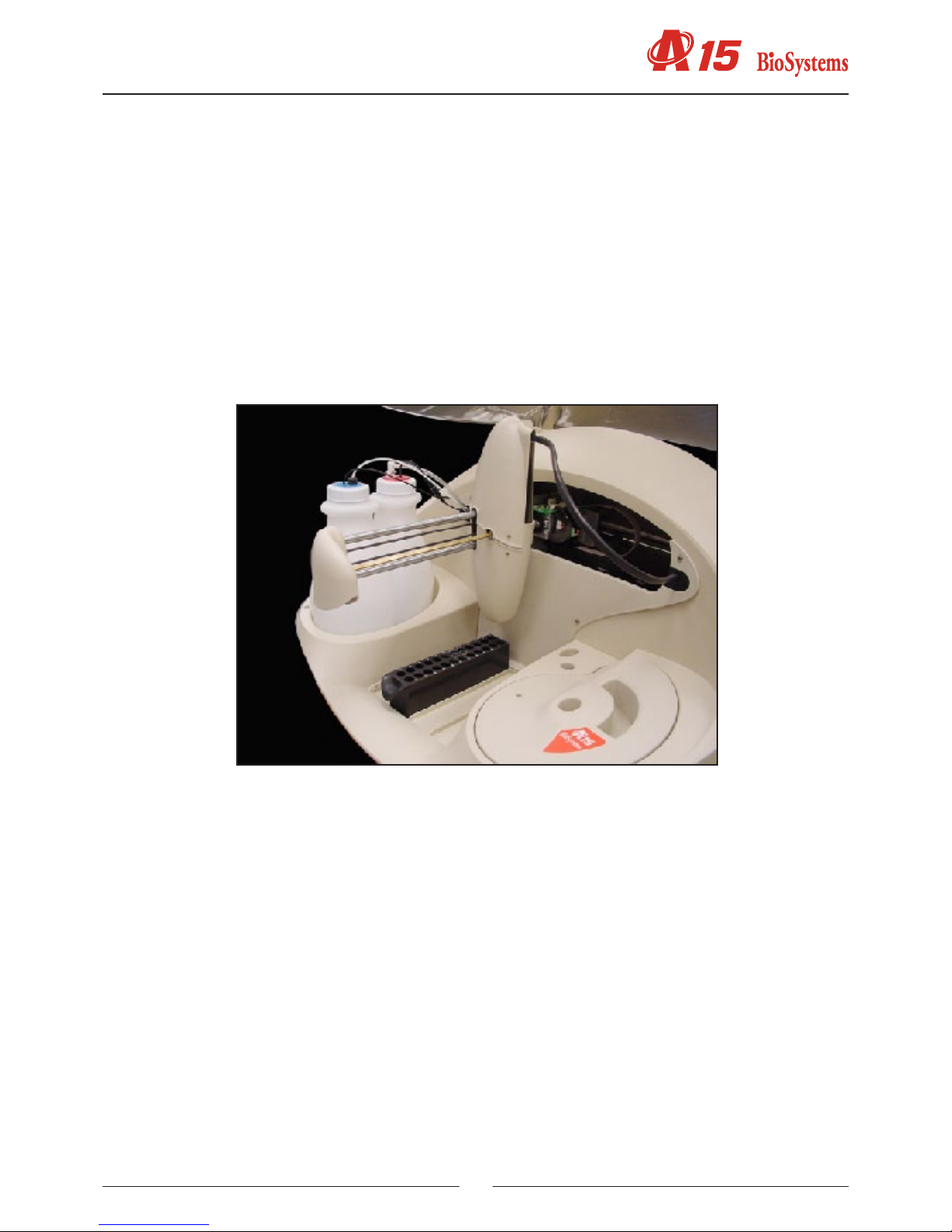
1.1.2. Dispensing system
This system consists of a thermostated needle, supported and displaced by an operating arm and connected to a
dispensing pump. The needle is detachable to enable cleaning and replacement. The analyser has capacity level
detection to control the level of the bottles and tubes and prevent the needle from penetrating too far into the corre-
sponding liquids, thus minimising contamination. An automatic adjustment system informs the user if the needle is not
mounted or if it is too bent. The needle has a sophisticated Peltier thermostatation system, with PID control, capable
of thermostating the preparations at approximately 37º in less than 15 seconds. Dispensing is carried out by means
of a low maintenance ceramic piston pump driven by a step-by-step motor. It is capable of dispensing between 3 and
1250 ml. The exterior of the needle is kept constantly clean by a wash station included in the base. A membrane pump
transports the waste to the corresponding container.
The A15 analyser has a tray with 4 free positions for racks of reagents or samples. Each reagents rack can carry up
to 10 reagents in 20 ml or 50 ml bottles. Each samples rack can contain up to 24 tubes of samples. The samples can
be patients, calibrators or controls. The analyser can be congured to work with 13 mm or 15 mm diameter tubes of
samples with a length of up to 100 mm or with paediatric wells. Any possible conguration of racks can be mounted
from 1 rack of reagents (10 reagents) and 3 racks of samples (72 samples) to 3 racks of reagents (30 reagents) and
1 rack of samples (24 samples).
On the left of the analyser are the waste and distilled water containers. The analyser constantly controls the level of
these containers and issues the appropriate alerts if the distilled water is nearly empty or if the waste container is full.

Service manual
10
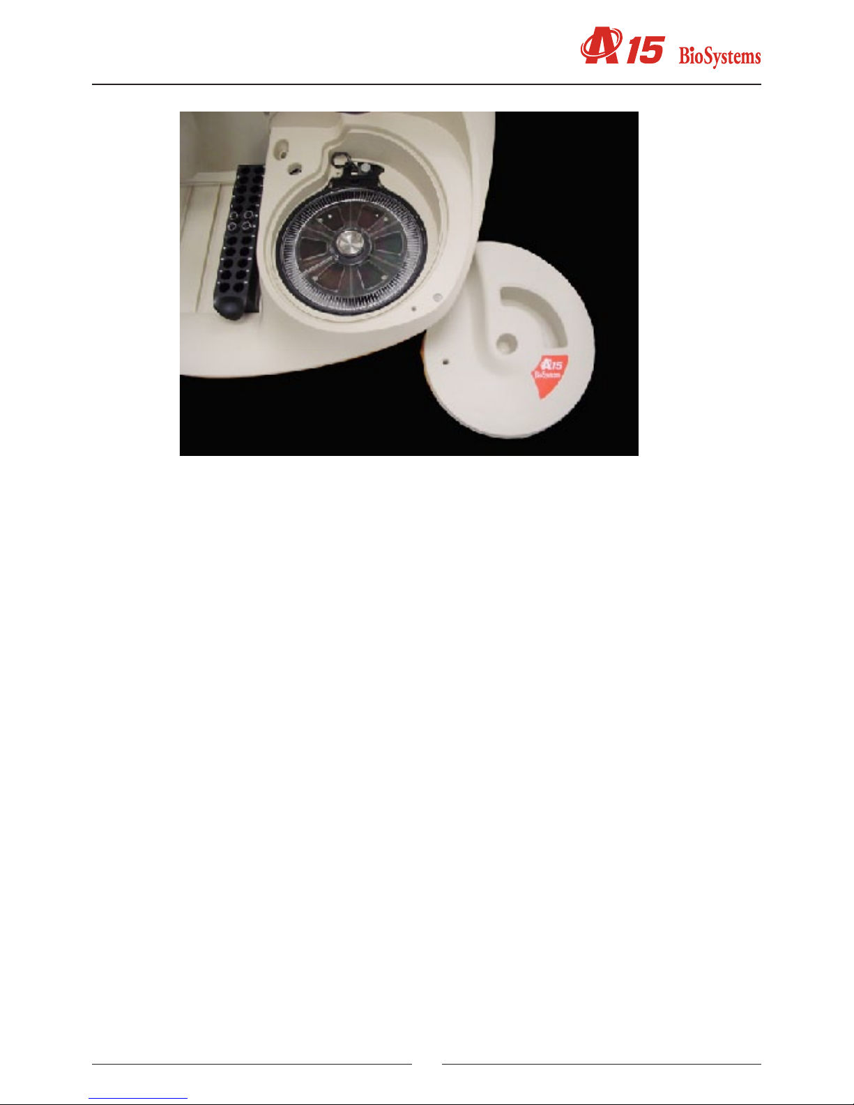
1.1.3. Reactions rotor and reading
The preparations are dispensed in an optical quality methacrylate reactions rotor thermostated at 37ºC. The optical
absorbance readings are taken directly on this rotor. Each reaction can be read for 10 minutes. The readings are
taken as they are programmed in each measurement procedure. The reaction wells have been designed to enable
the mixture of the sample and the reagent during the dispensing. Each rotor has 120 reaction wells. The length of the
light path is 6 mm. The minimum volume required to take the optical reading is 200 uL. The wells have a maximum
useful capacity of 800 uL. When the reactions rotor is completely full, the user must change it for one that is empty,
clean and dry. The reactions rotors can be reused up to 5 times if they are carefully cleaned immediately after use.
The Cleaning the semi-disposable reactions rotor section in the Installation and maintenance manual describes how
to clean the rotors. The user has a test in the computer programme, which he or she may use to check the condition
of the rotor. The rotor is driven by a step-by-step motor with a transmission. A Peltier system with PID control ther-
mostates the rotor at 37ºC.
An optical system integrated in the rotor takes the readings directly on the reaction wells. The light source is a 10 W
halogen lamp. The detector is a silicon photodiode. The wavelength is selected by a drum with 9 positions available
for optic lters. The lters are easily ch an ged by the user from the exterior of the analyser, without the need for disas-
sembling the lter drum. A step-by-step motor positions the drum. The optical system is capable of taking 1.25 readings
per second, with or without a lter change in between. The light beam from the lamp passes through a compensated
interferential lter to select the desired wavelength. It then passes through the rotor well and nally reaches the pho-
todiode, where the light signal is turned into an electric signal. A sophisticated analogical digital integrator-converter
system converts the electric signal into a digital value with which the analyser obtains the absorbance values. The
optical system continues to work when the general cover of the analyser is open, whereby the analyser can continue
to take readings while the user handles, for example, the sample tubes or the reagent bottles. The rotor cover must
be in place for the optical system to work correctly.
11
A detector tells the analyser of the presence of the cover. The analyser aborts the readings if the user removes the
rotor cover while the optical system is taking photometric measurements. If the rotor is not covered, the analyser
informs the user so that he or she places the rotor cover when it sends samples to be analyzed.
1.1.4. Electronic system
The described elements are controlled by an electronic system based on a microprocessor. The microprocessor has
two external communication channels to connect the instrument to the computer containing the application program.
The electronic system is made up of the following independent boards:
- Microprocessor board
- Photometric system board
- Needle conditioning board
- Fluid system interconnection board
- Arm interconnection board
- Rotor interconnection board
- Power supply board
1.1.5. Application program
The application program makes it possible to control all the operations of the analyzer. From this program, the user
can monitor the state of the analyzer and the work session, program parameters, e.g. technique parameters, prepare
the work session, prepare results reports, congure different analyzer options, activate various test utilities, prepare
and maintain the instrument and carry out internal quality control processes. The purpose of this manual is not to
explain the functioning of the user program. For detailed information to this regard, please consult the User Manual
included with the analyzer.
1.2. FUNCTIONING OF THE ANALYSER
The A15 analyser is an automatic random access analyser specially designed for performing biochemical and turbi-
dimetric clinical analyses. The analyser performs patient-by-patient analyses and enables the continual introduction
of samples. The analyser is controlled from a dedicated PC that is permanently communicated to the instrument.
The programme, installed on the computer, keeps the user constantly informed of the status of the analyser and the
progress of the analyses. As results are obtained, the computer shows them to the user immediately.
When a Work Session is begun, the analyser proposes performing the blanks, calibrators and controls programmed

Service manual
12
for the measurement procedures it is to carry out. The user may choose between performing the blanks and the
calibrators or not. If they are not performed, the analyser uses the last available memorised data. The controls can
also be activated or not. During a session, while the analyser is working, the user can introduce new normal or urgent
samples to be analyzed. Each time a new sample is added, the analyser automatically proposes the possible new
blanks, calibrators or controls to be performed. A work session can remain open for one or more days. When a session
is closed and another new session is opened (Reset Session), the analyser again proposes performing the blanks,
calibrators and controls. It is recommended that the session is reset each working day.
The analyser determines the concentrations of the analytes based on optical absorbance measurements. To measure
the concentration of a certain analyte in a sample, the analyser uses a pipette to take a specic volume of the sample
and the corresponding reagent, quickly thermostates them in the needle itself and dispenses them into the reactions
rotor. The very dispensing speed together with the geometry of the reaction well causes the mixture to be shaken and
the chemical reaction begins. In the bireagent modes, the reaction begins when the analyser later dispenses a second
reagent in the same reaction well. The reactions can be biochemical or turbidimetric. In both cases, the reaction or
the chain of reactions produced generate substances that attenuate certain wavelengths, either by absorption or by
dispersion. Comparing the light intensity of a certain wavelength that crosses a well when there is a reaction and when
there is not a reaction can determine the concentration of the corresponding analyte. This comparison is quantied
with the physical magnitude called absorbance. In some cases, the concentration is a direct function of the absorb-
ance, and in other cases, it is a function of the variation of the absorbance over time, depending on the analysis mode.
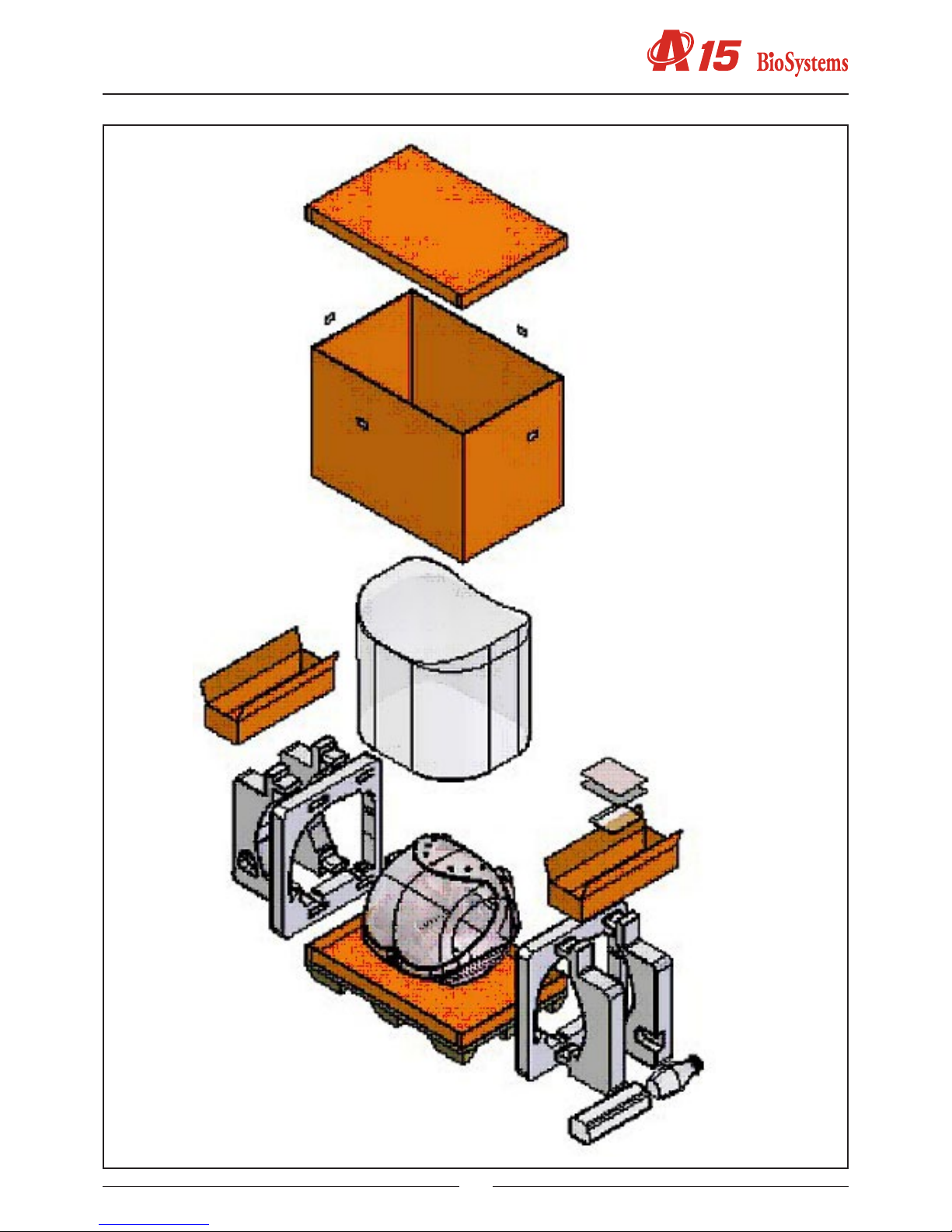
1.3. TRANSPORT AND RESHIPMENT OF THE ANALYZER
If the analyser is to be reshipped or moved using a transport vehicle, it is important to block the operating arm and
use the original packaging to ensure that the apparatus is not damaged. To package the instrument, we recommend
you follow the following instructions: (on the unpackaging instructions sheet)
13

Service manual
14
2. MECHANICAL ELEMENTS
2.1. Instrument breakdown
The physical structure of the analyzer can be broken down as follows:
-Operating arm
-X guide
-Y guide
-X carriage
-Y carriage
-Needle unit
-Dispensing system
-Thermostated probe
-Dispensing pump
-Tubes and containers
-Container level control sensors
-Racks tray with integrated washing station
-Waste pump
-Reactions rotor with integrated optical system
-Thermostated rotor and photometric system. This contains the electronic photometric system board
-Lighting system
-Electronics box.This houses the electronic boards of the microprocessor, the power supply and the front indicator
-Main cover hinges
-Base
-Housings
-Upper casing
-Front housing
-Arm casing
-Main cover
The following is a brief description of each of the mechanical elements that make up the analyzer.
2.2. Description of the mechanical elements
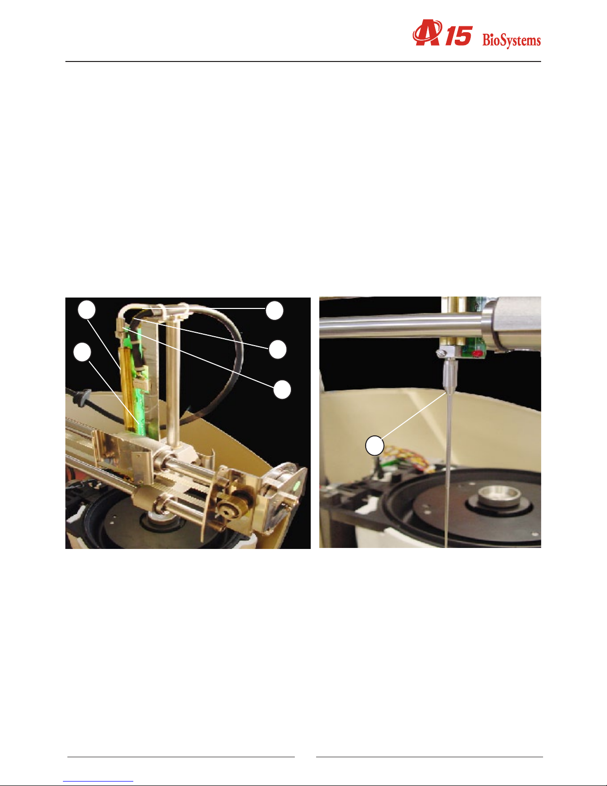
2.2.1. Operating arm
This mechanism positions the dispensing needle appropriately during the preparation of the analyses. An encoder
checks the vertical movement of the needle and a spring automatically stops it from falling in the case of a power cut.
The dispensing pipe and the electrical hoses of the arm pass through the front casing
(1) X GUIDE
(2) X CARRIAGE
(3) Y CARRIAGE
(4) Y GUIDE
(5) NEEDLE UNIT
(6) CONTROL AND DISPENSING PIPE HOSE
The needle unit (5) supports the thermostated needle and can move on the Y carriage (3), which can move on the
Y axes (4). The Y axes are supported by the X carriage, which moves on the X axes (1). In this way, the needle can
be moved in the three Cartesian directions of X, Y and Z. The hose (6) houses the Teon dispensing tube and all the
electrical hoses of the arm.
15
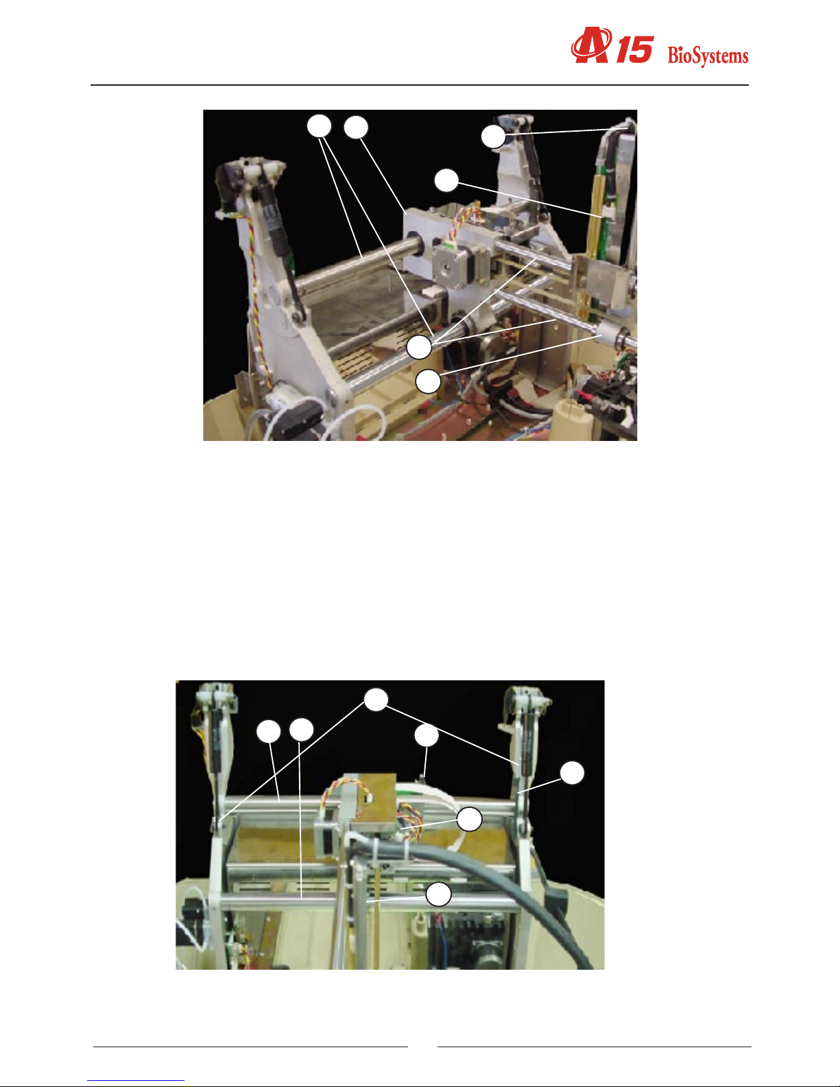
2.2.1.1. X Guide.
(1) UPPER X TOOTHED AXIS
(2) LOWER X AXIS
(3) X START PHOTOSENSOR
(4) BEARING X AXIS
(5) X MOTOR
(6) X START PHOTOSENSOR TAB
(7) AXIS SUPPORTS
This consists of two supports (7) that hold the steel axes (1 and 2) on which the X carriage moves. The photosensor
(3) indicates the start position of the X carriage movement. The motor X (5) is moved by a rack (2). The X carriage is
supported by the second axis (2) by means of a bearing (4).
13
6
4
5
2
7
12
3
4
5
6

Service manual
16
2.2.1.2. X Carriage
(1) X CARRIAGE BODY
(2) UPPER X AXIS - RACK
(3) LOWER X AXIS
(4) X MOTOR
(5) Z MOTOR
(6) ENCODER
(7) XYZ INTERCONNECTION PCB
(8) BEARINGS
The X carriage body (1) moves along the two axes (2, 3). The upper axis (2) acts as a rack. The X motor (4) is tted
with a pinion that moves the carriage. The X carriage also supports the interconnection PCB (7) and the Z motor (5).
To enable the movement, it uses linear bearings (8).
2.2.1.3. Y Carriage
(1) Y CARRIAGE BODY
(2) Y GUIDE AXES
(3) Y MOTOR
(4) BELT
(5) BELT RETURN PULLEY
(6) START PHOTOSENSOR
(7) START TAB
(8) NEEDLE UNIT
(9) BEARINGS
The body of the Y carriage (1) moves along the two axes (2) on linear bearings (9). The said axes are supported by
the X carriage. The movement is made by the Y motor (3) by the belt (4) and the return pulley (5). The start of the
movement is controlled by the tab (7) and the start photosensor (6) located on the X carriage (10). The body of the Y
carriage (1) also supports the needle unit.
12
3
4
5
6
7
8

17
1
2
3
4
5
6
7
9
8
10

Service manual
18
2.2.1.4. Needle unit
(1) Z GUIDE
(2) RACK
(3) Z MOTOR
(4) ENCODER
(5) TRANSMISSION AXIS
(6) RETURN SPRING
(7) THERMOSTATATION PIPE
(8) CONTROL PCB
(9) Y CARRIAGE
The Z guide (1) supports the thermostatation pipe (7) and the control PCB (8) where the heating elements are located,
together with the thermistor signal amplier and level detection and the Z axis start photosensor. The rack (2) supports
the Z guide (1) which crosses the Y carriage (9) on two bearings. The Z motor (3) is fastened to the X carriage (10)
and is moved by a transmission axis (5) tted with a pinion that acts on the rack. The return spring (6) acts on the
transmission axis and prevents the needle from falling in the event of a power cut: The encoder (4), which detects any
obstruction to the movement of the thermostated needle (9) is located on the same axis and on the part of the motor.
3
1
10
5
4
8
7
6
2
9
19
1
2
3
4
5
6
2.2.2. Dispensing system
The dispensing pump dispenses the preparations through the thermostated needle. The needle is washed internally
and externally at the washing station. The racks tray makes it possible to position the samples to be analyzed and
the required reagents. The level of the distilled water and waste containers is controlled by the analyzer by capacity.
2.2.2.1. Thermostated probe
(1) THERMOSTATATION PIPE
(2) PCB
(3) TEFLON DISPENSING TUBE
(4) ELECTRICAL CONTROL HOSE
(5) FASTENING NUT
(6) REMOVABLE NEEDLE
The thermostatation pipe (1) preheats the reagent during dispensing. It is tted with two connectors at each end. The
removable needle (6) is connected to one and the Teon dispensing pipe (3) is connected to the other, xed by the
fastening connector (5). The PCB (2) contains the thermostatation elements, the thermistor and associated circuits.
The various thermistor and element action signals (3) pass through the hose (4).
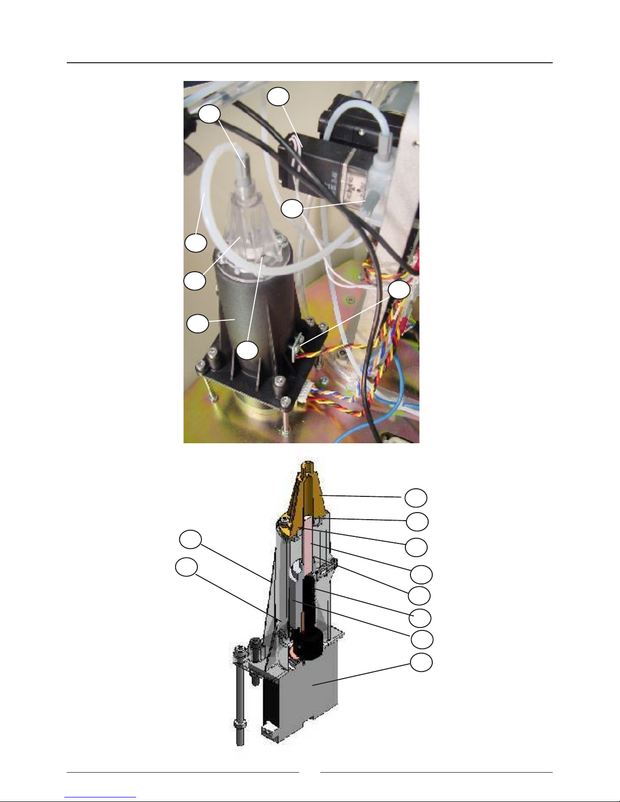
2.2.2.2. Dispensing pump
(1) BODY
(2) FLUIDIC CHAMBER
(3) SEAL
(4) SEAL SUPPORT
(5) CERAMIC PISTON
(6) PISTON SUPPORT
(7) START DETECTION BARRIER
(8) AXIAL BEARING
(9) ENDLESS SCREW
(10) MOTOR
(11) START PHOTOSENSOR
(12) PUMP NUT
(13) PUMP-ELECTROVALVE TEFLON TUBE
Service manual
20
1
2
3
4
5
6
7
9
8
10
1
2
3
11
12
13
14
15
Table of contents
Other biosystems Laboratory Equipment manuals


