6 7
Instructions for Use Sarpette® MInstructions for Use Sarpette® M
4.2 Cleaning
The removed volume unit (lower part) of the pipette can be cleaned with water or alcohol. In cases of heavy
soiling, the individual parts can also be immersed in a disinfectant solution. Proper cleaning is necessary if liquid
has inadvertently penetrated into the pipette interior. Rinse and dry the instrument before assembly. Remove
particularlystubbornresiduesintheultrasonicbath.Beforeassemblingthepipette,lightlygreasetheO-ring(see
below).
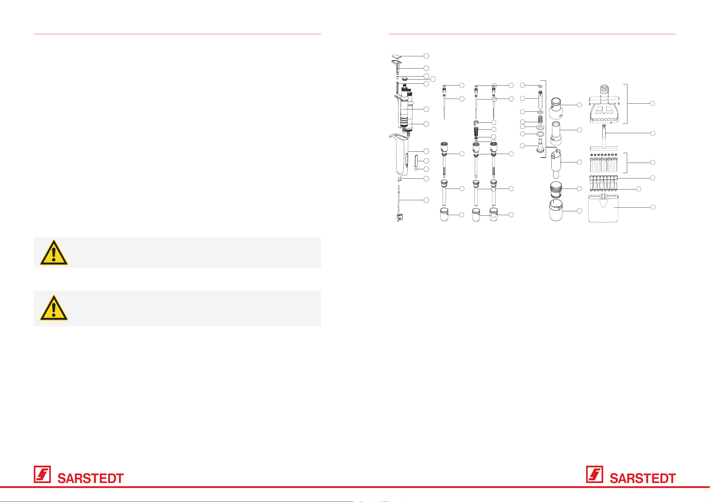
4.3 Disassembly of the volume unit and replacement of the O-ring, models – 1000 µl (Fig. 6)
4.3.1 Remove the volume unit (lower part):
1. Press the ejection button (2), turn the ejection nut (20) or (24) to the left for 2 ml and remove.
2. Unscrew the cylinder (18).
3. Push the operating button down completely, then pull out the piston.
4.3.2 Replacing the O-ring and PTFE sleeve:
1. After removing the lower part, remove the cylinder (18) and press it onto both mandrels of the ring (14) with
the aid of a pipette tip or a pointed object.
2. Release the cylinder ring, pull out the spring (15) to reach the O-ring/PTFE sleeve.
3. Replace defective parts. Remove excess grease from the piston (13).
To avoid possible damage to the PTFE sleeve, place it on
the piston (13) and only then attach the O-ring (17).
4. Lightly grease the piston, PTFE sleeve and O-ring and reassemble the volume unit.
TheO-ringSealCuAssemblyisnotaccessibleon2,10,10Yand20μlmodels.Ifthereisa
lack of tightness, the complete cylinder must be replaced.
4.3.3 Replacing the O-ring:
1. Unscrew the piston rod (21), remove the spring positioners (22, 23) and the spring (15).
2. If necessary, replace defective parts. Grease the O-ring (17) and cylinder (18) evenly.
4.4 Disassembly of the volume unit and replacement of the O-ring, models 5 and 10 ml (Fig. 7)
2
34
5
6
7
8
9
10
11
33
12
13
18
19
20
12
14
15
16
17
22
21
15
23
17
13
24
25
18
26
20
815 : 1, 2, 5, 10 L
825 : 2, 10 L
(except 825.0010Y)
815/825 : all other models 835 : all models
12
13
18
19
20
12
13
18
19
20
14
15
16
17
22
21
15
23
17
13
24
25
18
26
20
815 : 1, 2, 5, 10 L
825 : 2, 10 L
(except 825.0010Y)
815/825 : all other models 835 : all models
12
13
18
19
20
815 : 1, 2, 5, 10 L
825 : 2, 10 L
(except 825.0010Y)
12
13
18
19
20
815/825:
all other sizes
815:
1,2, 5, 10, 20 µL
825:
2, 10, 10Y, 20 µL
All models
12
22
21
15
23
17
13
24
25
18
26
20
27
28
29
30
32
31
855: all sizes835: 5 and 10 mL
1. Ejector cushion 12. Circlip 23.Bottomspringpositioner
2. Ejection button 13. Piston 24 Ejection cap
3. Spring washer 14. Ring 25. Ejection sleeve
4. Smartie Cap 15. Spring 26. Ejection screw
5. Ejection spring 16. PTFE sleeve 27. Cover assembly
6. Counter unit (adjustable) 17. O-Ring (piston) 28. Arm
7.Dosingunit(x) 18. Cylinder 29. Piston assembly
8. Handpiece 19. Ejector 30. Cylinder unit
9. Window 20 Ejection nut 31. Housing
10 Screws, handpiece (2x) 21. Piston rod 32. O-ring (cone, 200 µl)
11. Ejection rod 22. Top spring positioner 33. Calibration slide
4.4.1 Remove the volume unit (lower part):
1. Turn the ejection nut (20) and separate it from the ejection cap (24).
2. Unscrew the cylinder (18), press the operating button, then pull out the piston.
4.4.2 Changing the O-ring:
1. Press down both clips of the cylinder (18) simultaneously and without exerting force and separate them from
the ejection sleeve (25). Remove piston assembly.
2. Unscrew the piston rod (21), remove the spring positioners (22, 23) and the spring (15).
3. If necessary, replace defective parts. Grease the O-ring (17) and cylinder (18) evenly.
4. Reassemble the piston assembly, cylinder and ejection sleeve.
5.Screwthecylinderontothepipette,presstheoperatingbutton(B)downfullyandlockthepistonrod.