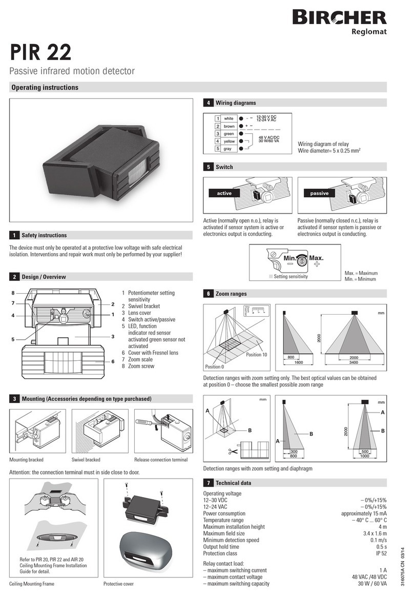
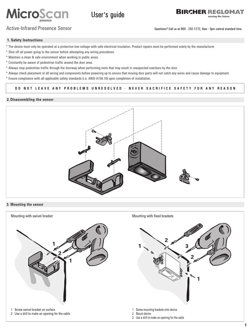
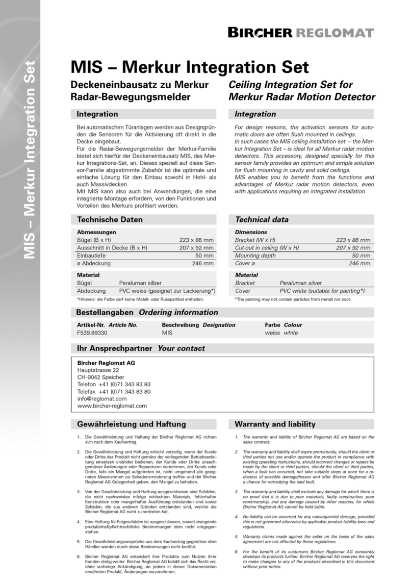
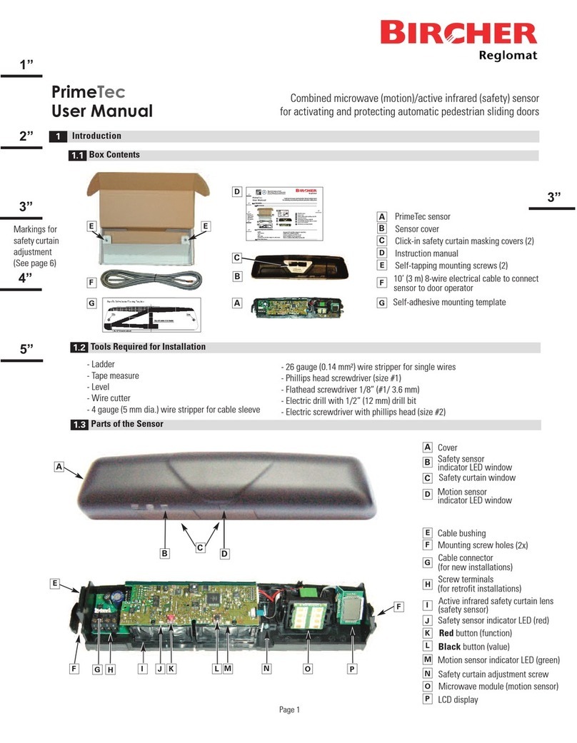
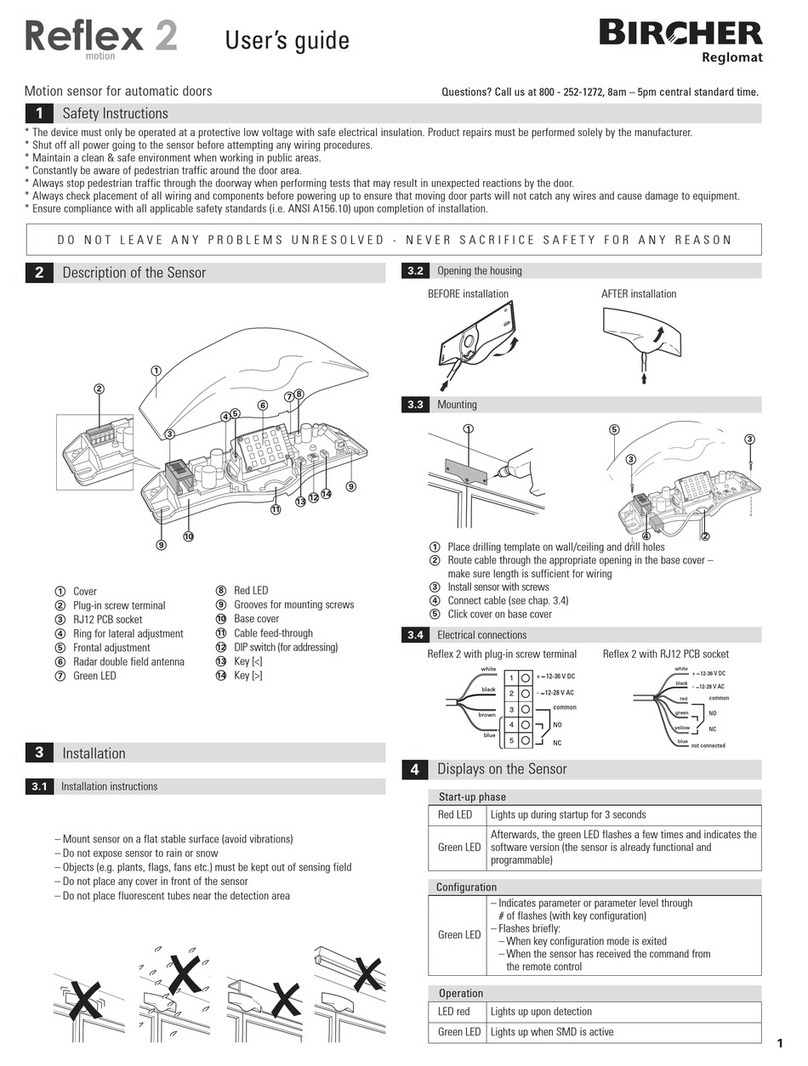
Bircher Reglomat ENT-R User manual

1
Safety edges
Translation of the original instructions
Appli ation
Types of mounting
1
Quality
international
level
EN ISO
9001
Self-assembly instructions for safety edges
(ENT-R, ENT-20, ENT-7, ENT-S)
Safety edges (sensors) in combination with a switching unit (signal processing) are components of a safety system (protection system for person detection).
The system, or more specifically the safety edges, are used to safeguard shearing and crushing points on power-operated doors, gates and similar automatic
fixtures. The safety edges can be installed in any horizontal or vertical position, either singly or in combination.
Standard
Top, rubber profile losed:
- 1 end cap
- Profile chamber sealed
Bottom, rubber profile open:
(= no end cap and switching
chamber not sealed)
Preparing the safety edge and assembling the onta t strip
2
easuring the safety edge
2.1
Trim aluminium profile to match length of protected area and plan type and manner of cable feed-through, drill holes (counterbores) and profile holders.
Aluminium profile length = Rubber profile length (L)
Trimming the rubber profile
2.2
L
5 mm
Using the rubber
shears, trim the rubber
profile to the desired
length L.
The swit hing hamber for the onta t strip must not be damaged unne essarily as in oming water may impair the safety fun tion
of the strip.
For the cable feed-through,
make a small hole (1/10 mm
smaller than the cable diame-
ter) hole punch pliers about
5mm from the edge.
Option for verti al appli ations
(dependent on enviromental conditions)
End aps on both ends
Trimming the contact strip
2.3
L - X
Trim the contact strip to length (L – X). Be sure to cut at right angles!
The onta t strip is shorter than the rubber profile
by the length of the end pie es used:
Cable and end pie e Cable (both ends)
X = 55 mm 60 mm
ENGLISH
Bottom, rubber profile losed:
- 1 end cap
- Profile chamber sealed

Crimping the end pieces
2.5
Using the crimping tool, crimp the end pieces at both ends and check they are secure.
Squeeze pliers firmly together.
Noti e:
For contact strips ENT-R and ENT-20, end pieces ENEH-... must be crimped on with ES-PRESS
pliers (ClickLine and CoverLine).
For contact strips ENT-7 and ENT-S, use ENES-... end pieces and ESS-PRESS (S-Line) pliers.
Fitting the end pieces
2.4
easure off and mark a point exactly 10 mm from each end of the contact strip.
Then slide on the end pieces up to the marks (tolerance ±1 mm).
Testing the contact strip
2.6
Warning: The onta t strip must be tested with an ohmmeter to ensure
orre t fun tioning BEFORE it is fitted in the rubber profile!
In the ase of two-ended ables, test both ends!
Feeding in the contact strip
2.7
When feeding the contact strip into the rubber profile, no lubricants such as water, talc, oils,
greases or silicone spray, should be used.
Otherwise, the sealing compound applied later on will not bond with the rubber profile and
seal the switching chamber.
Noti e: If the rubber profile is longer than about 3 m, it is advisable to pass a length of string
through the profile first using compressed air. Tie the string to the cable end of the contact
strip and then pull the strip through – do not tear! A stiff piece of wire is also a suitable aid.
Be careful not to damage the switching chamber when feeding through the contact strip!
Noti e: For profiles EPE040/105 and EPE040/081, the arms must be folded up by 90 degrees
before feeding the contact strip through in order to open up the switching chamber to
assist in assembly .
Warning: Before sealing, he k the fun tionality ( onta t-making) of the
safety edge again using an ohmmeter! In the ase of two-ended ables,
test both ends!
ENT-R
ENT-20
ENT-7
ENT-S
Profile must be straight
ES-PRESS ESS-PRESS
End pie es
ENEH-8
ENES-8
ENEH-0
ENES-0
ENEH-K...
ENES-K...
8.1 - 8.5 kΩ∞ ∞
< 200 Ω< 200 Ω< 200 Ω

3
4Fill rubber profile chamber
with sealing compound
ES-BD, at least 1 x 10 cm
(S-Line: 2 cm) strip.
5
EN-DL
3
ES-KLEBER
Wrap half strip
of sealing
compound around
cable and pull through
hole. Hole must be
completely sealed!
Apply sealing compound
to switching chamber,
at least 1 x 10 cm
(S-Line: 2 cm)
strip of compound
ES-BD
Sealing the switching chambers in the rubber profile
3.2
Standard
approx. 2.5 cm
approx. 3 cm Profile
EN-DS
EN-DL
Sealing compound
ES-BD
Sealing compound
ES-BD
Cable
Profile
EN-DL
Sealing compound
ES-BD
Cable
Profile open
at bottom
approx. 3 cm
Profile
open
Profile
closed
End cap
NB: End cap only if rubber profile is sealed
Assembling the safety edge
3
Types of mounting for the safety edge
3.1
Apply sealing compound to switching chamber
Slide sealing plug EN-DL over cable, inserting at least
4 mm into the profile. Sealing plug EN-DS without hole
on the side without a cable.
Fix sealing plug (including cable feed-through at cable end)
in rubber profile by applying ES-KLEBER all the way round
and leave to dry briefly.
Wrap ES-BD sealing compound around cable and pull through hole made
with punch pliers using long-nosed pliers. The hole must be completely
sealed with the compound.
Then fill the rest of the switching chamber with sealing compound and
press down well.
For ELE040/081 and ELE040/105: apply EN-KAS
1
Option for verti al appli ations (sliding gates) only
End cap

ounting the rubber profile
4.2
oisten «click-fit foot» rubber profiles with a solution of soapy water and press into the alumi-
nium profile (do not pull in).
To ensure orre t fun tioning of safety edges with a li k-fit foot, after
mounting, the safety edge must be pressed in along its entire length to
make sure the foot engages properly in the aluminium bar.
Otherwise, the safety edge will onne t through. Che k fit of rubber profile
in aluminium strip.
2
2
Final checks
4.3
Check the resistance of the safety edge with an ohmmeter.
Noti e: The overall safety of the machine and its protection systems
depends on the quality, reliability and correct connection of the interfaces.
Warning: Perform a final fun tional and visual he k of the safety edge. On e mounting is omplete, test the safety edge on
the obje t to make sure it fun tions orre tly. The prote tion system must also satisfy the for e, overtravel and sensitivity
requirements of the standards appli able in the relevant ountry.
indestens jährliche Funktions- und Sichtkontrolle der Sicherheitsleiste durch ausgebildetes Personal.
The safety edge is maintenance-free. If damage occurs, such as a brittle or torn rubber profile, non-tight switching chamber, insuffi ient onta t
resistan e in the a tivated state (>500 ohms) or similar, the safety edge must be replaced immediately. Please request a new one, remembering
to state the product designation.
Check the resistance of the safety edge with an ohmmeter, referring to the table above.
Maintenan e
5
6Conta t details
Manufacturer:
Bircher Reglo at AG
Wiesengasse 20
CH-8222 Beringen
Switzerland
www.bircher-reglo at.co
Press in profile at both ends
Work from outside inwards
Glueing on the end caps
3.3
ES-KLEBER
Attach end caps by applying ES-KLEBER to the points shown and hold in place, applying pressure across the whole area, for approx. 10 seconds.
Note: No end caps on ELE040/081 and ELE040/105
Attaching aluminium strip
4.1
Attach aluminium strip to object with ountersunk head s rews. Recommended hole
spacing 300 mm. ake sure aluminium strip is securely attached to ends of safety edge.
You may have to make holes for the cable to exit through.
NB: In the case of 2-panel systems, the two profiles should be aligned facing each other.
The same applies to any counter sealing profile.
Noti e: If possible, avoid routing the cable through the aluminium profile as it may press
against the switching chamber.
T-foot rubber profiles should be pulled into the aluminium.
Any burrs on the aluminium profile must be removed first.
End pie es
ENEH-8
ENES-8
ENEH-0
ENES-0
ENEH-K...
ENES-K...
8.1 - 8.5 kΩ∞ ∞
< 200 Ω< 200 Ω< 200 Ω
Mounting the safety edge
4
xxxxxxA02/11
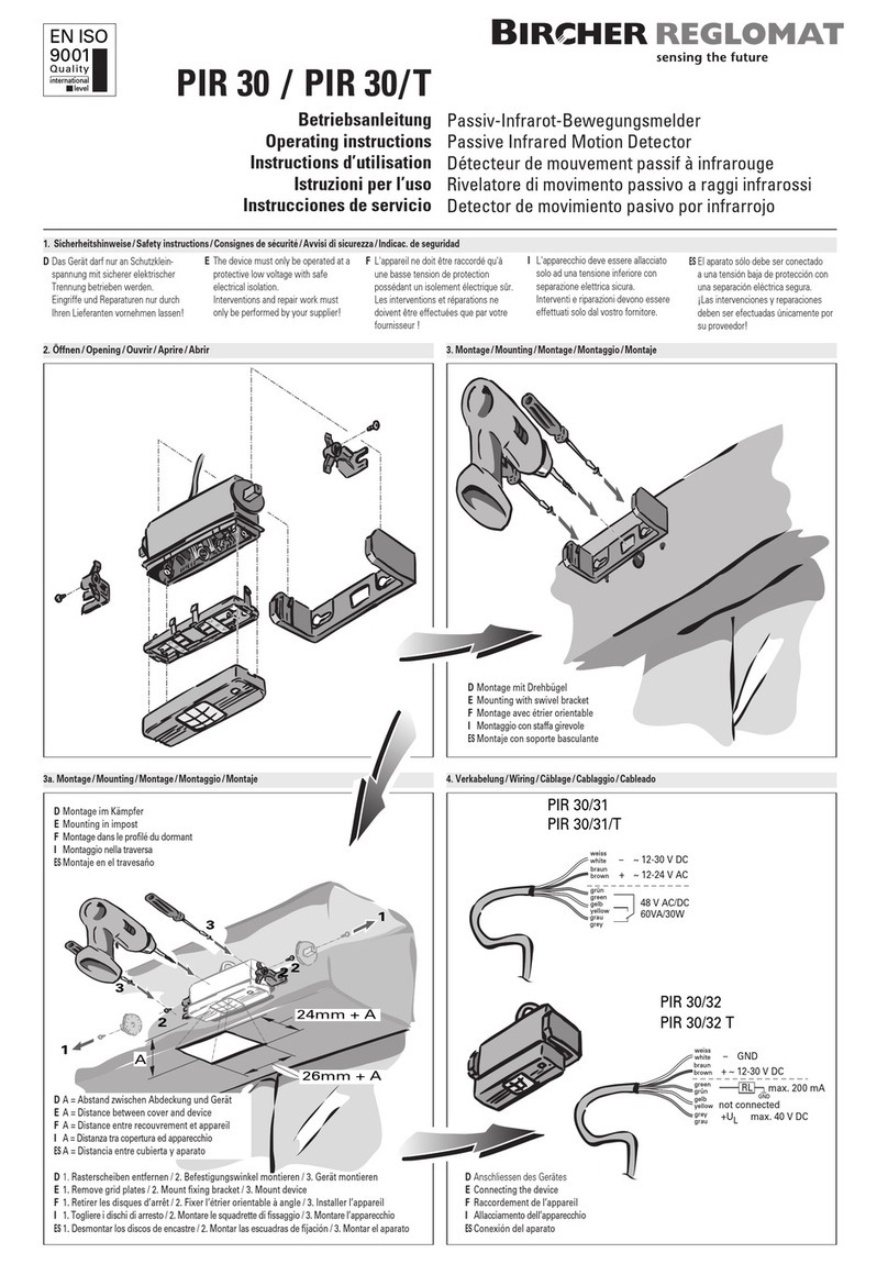
This manual suits for next models
3
Other Bircher Reglomat Accessories manuals

Bircher Reglomat
Bircher Reglomat MIS User manual

Bircher Reglomat
Bircher Reglomat MicroScan User manual

Bircher Reglomat
Bircher Reglomat Reflex motion 2 User manual

Bircher Reglomat
Bircher Reglomat PrimeTec User manual

Bircher Reglomat
Bircher Reglomat PIR 22 User manual

Bircher Reglomat
Bircher Reglomat PIR 30 User manual