PIR 22
Passive infrared motion detector
Operating instructions
Safety instructions1
Mounting (Accessories depending on type purchased)3
Wiring diagrams4
Switch5
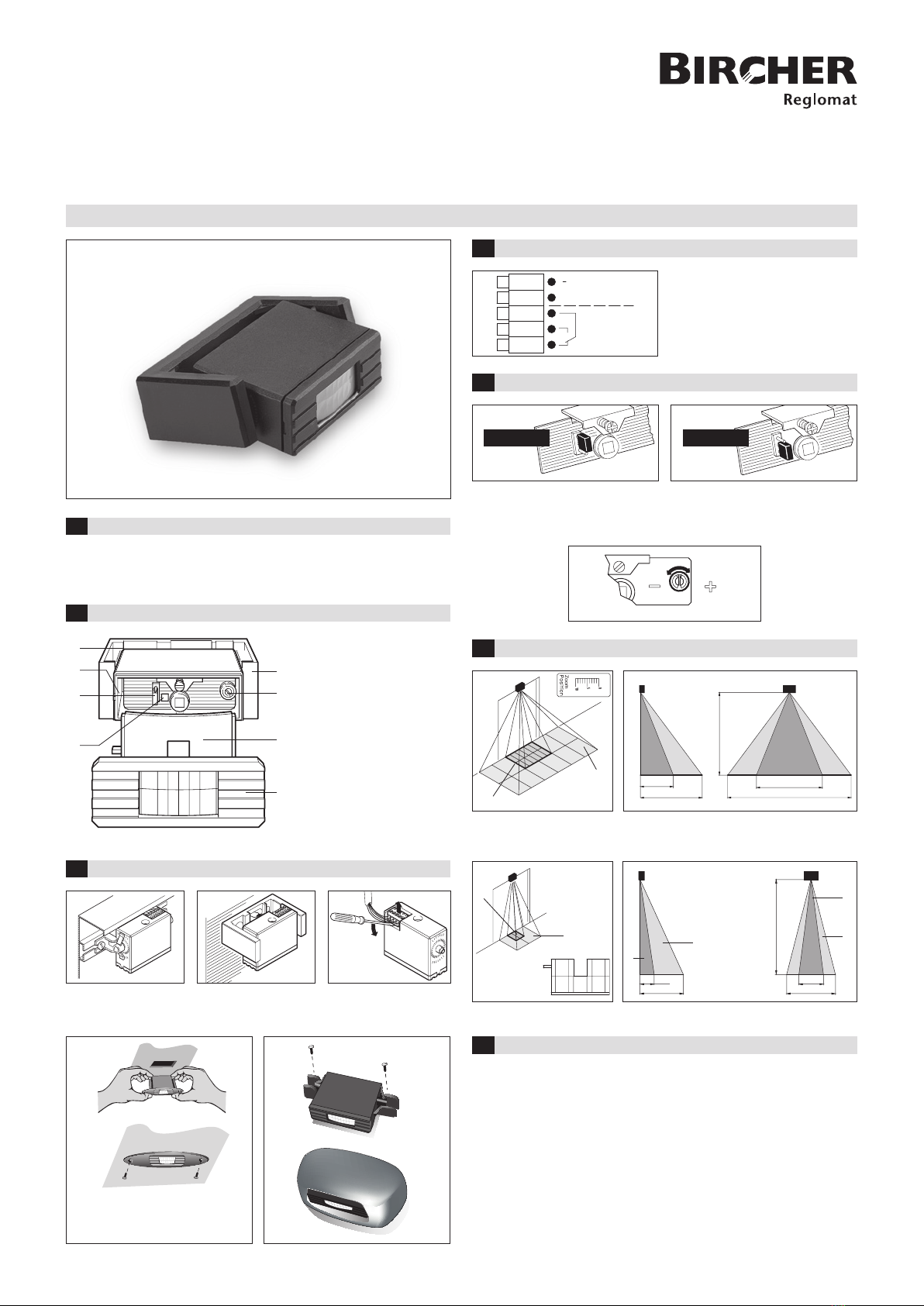
Zoom ranges5
Technical data7
Design / Overview2
The device must only be operated at a protective low voltage with safe electrical
isolation. Interventions and repair work must only be performed by your supplier!
1 Potentiometer setting
sensitivity
2 Swivel bracket
3 Lens cover
4 Switch active/passive
5 LED, function
indicator red sensor
activated green sensor not
activated
6 Cover with Fresnel lens
7 Zoom scale
8 Zoom screw
Mounting bracked Swivel bracked Release connection terminal
Attention: the connection terminal must in side close to door.
Ceiling Mounting Frame Protective cover
Refer to PIR 20, PIR 22 and AIR 20
Ceiling Mounting Frame Installation
Guide for detail.
1
2
3
4
5
white
brown
green
yellow
gray
12-30 V DC
+
48 V AC/DC
30 W/60 VA
12-24 V AC
~
~
Min. Max.
800
1600
2000
3400
2000
mm
Wiring diagram of relay
Wire diameter= 5 x 0.25 mm2
2
1
3
6
8
7
4
5
active passive
Active (normally open n.o.), relay is
activated if sensor system is active or
electronics output is conducting.
■Setting sensitivity Max. = Maximum
Min. = Minimum
Passive (normally closed n.c.), relay is
activated if sensor system is passive or
electronics output is conducting.
Operating voltage
12–30 VDC – 0%/+15%
12–24 VAC – 0%/+15%
Power consumption approximately 15 mA
Temperature range – 40° C ... 60° C
Maximum installation height 4 m
Maximum field size 3.4 x 1.6 m
Minimum detection speed 0.1 m/s
Output hold time 0.5 s
Protection class lP 52
Relay contact load:
– maximum switching current 1 A
– maximum contact voltage 48 VAC /48 VDC
– maximum switching capacity 30 W / 60 VA
Position 0
Position 10
Detection ranges with zoom setting only. The best optical values can be obtained
at position 0 – choose the smallest possible zoom range
Detection ranges with zoom setting and diaphragm
✂
mm
B
A
1000
500
2000
300
800
mm
BB
A
A
328872A CN 03/14
316075A CN 03/14
6


