Page 1
PrimeTec
User Manual
Introduction
IJK
H
O
G
LN
Combined microwave (motion)/active infrared (safety) sensor
for activating and protecting automatic pedestrian sliding doors
1
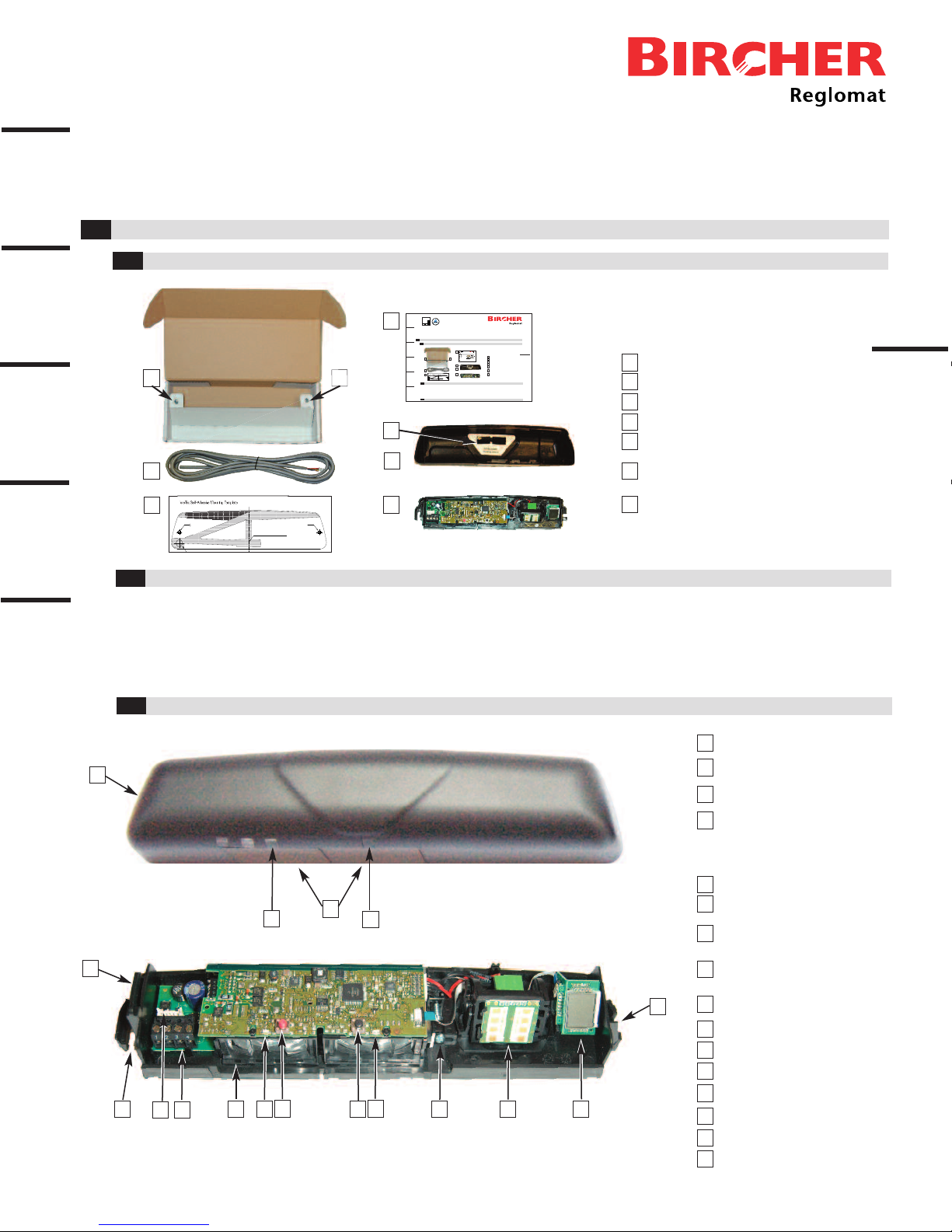
Box Contents
1.1
- Ladder
- Tape measure
- Level
- Wire cutter
- 4 gauge (5 mm dia.) wire stripper for cable sleeve
A
B
C
D
E
F
G
H
J
K
L
Cover
Safety curtain window
Safety sensor
indicator LED window
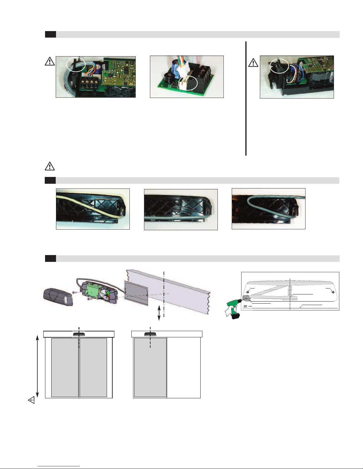
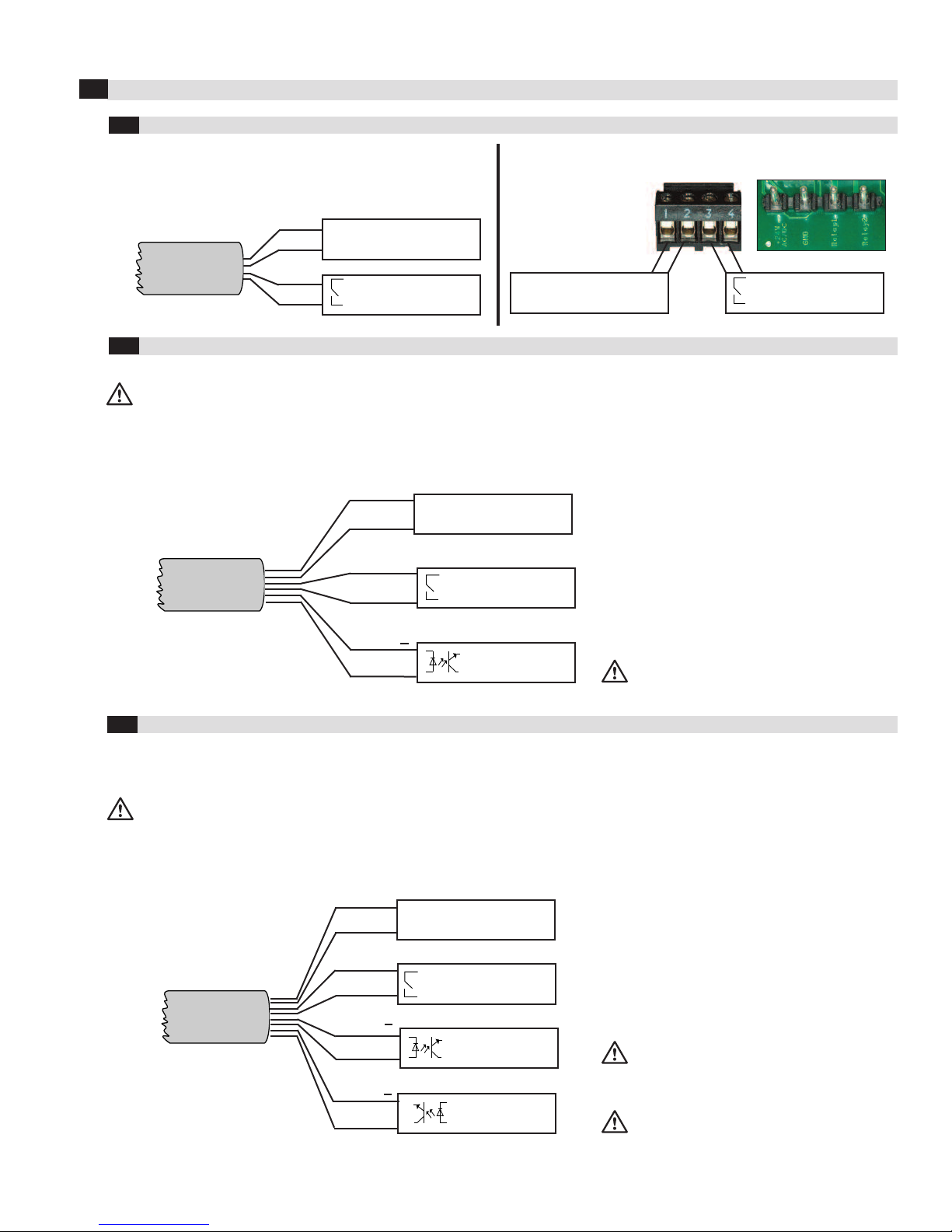
Cable bushing
Mounting screw holes (2x)
Cable connector
(for new installations)
Screw terminals
(for retrofit installations)
Safety sensor indicator LED (red)
Red button (function)
Black button (value)
Motion sensor indicator LED (green)
Parts of the Sensor
1.3
Motion sensor
indicator LED window
BD
C
E
M
A
F
I
M
FActive infrared safety curtain lens
(safety sensor)
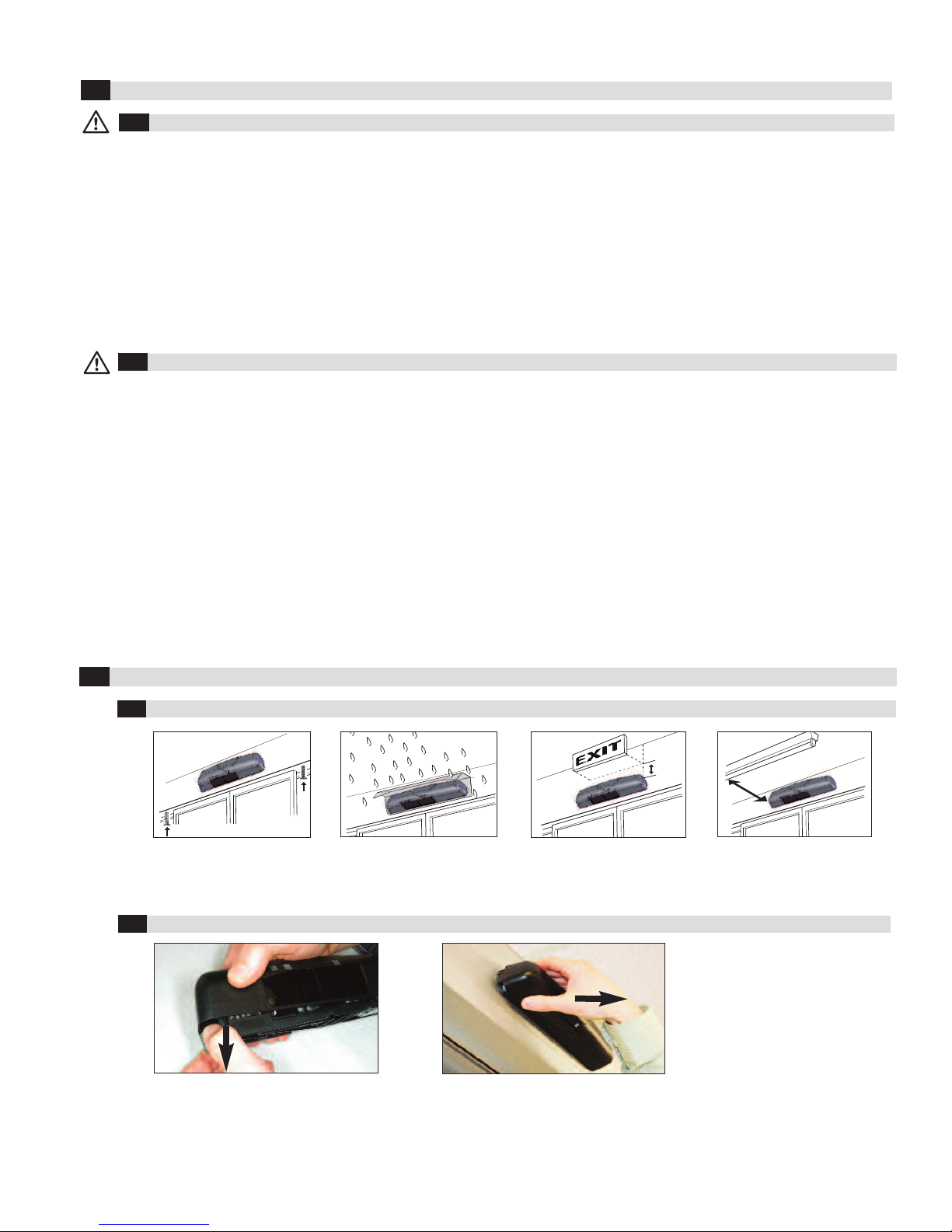
Markings for
safety curtain
adjustment
(See page 6)
3”
P
3”
2”
1”
A
B
C
C
D
F
GG
E
PrimeTec sensor
Sensor cover
Click-in safety curtain masking covers (2)
Instruction manual
Self-tapping mounting screws (2)
Self-adhesive mounting template
Safety curtain adjustment screw
Microwave module (motion sensor)
LCD display
N
O
P
A
B
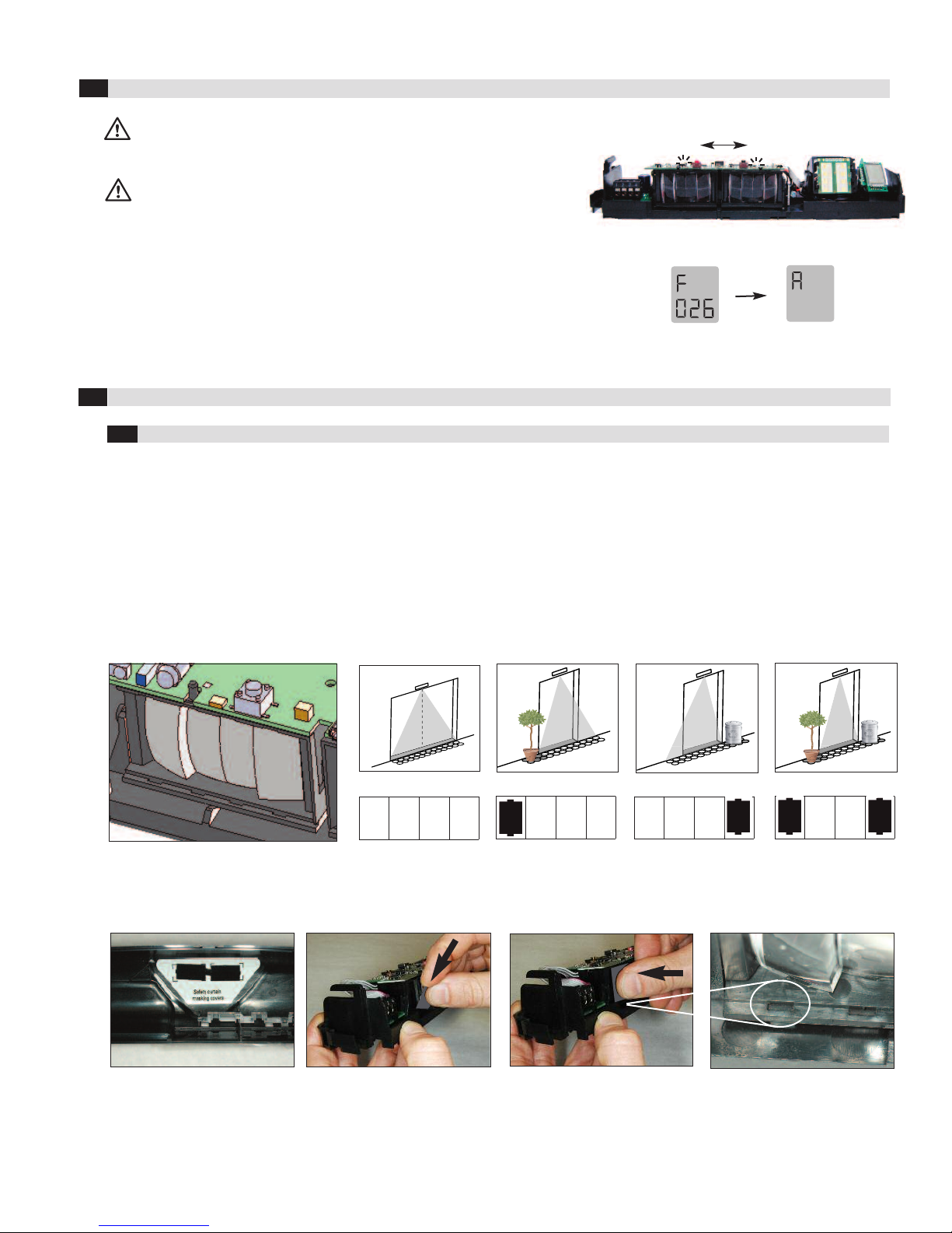
Align with center of door header
PrimeTec Self-Adhesive Mounting Template
Screw Screw
Dia. 1/2” (12 mm) for cable exit
0641&7%6+10
Quality
international
level
EN ISO
9001
Combined microwave (motion)/active infrared (safety) sensor
for activating and protecting automatic pedestrian sliding doors
Box Contents
- Ladder
- Tape measure
- Level
- Wire cutter
- 4 gauge (5 mm dia.) wire stripper for cable sleeve
arts of the Sensor
This product meets or exceeds
ANSI standard 156.10 as independently
tested by TÜ Rheinland North America
Markings for
safety curtain
adjustment
(See page 6)
PrimeTec sensor
Sensor cover
Click-in safety curtain masking covers (2)
Instruction manual
Self-tapping mounting screws (2)
Self-adhesive mounting template
S
Alignwithcenterofdoorheader
PrimeTecSelf-AdhesiveMountingTemplate
Screw Screw
Dia.1/2”(12mm)forcable exit
0641&7%6+10
Quality
international
level
ENISO
9001
Combined microwave (motion)/active infrared (safety) sensor
for activating and protecting automatic pedestrian sliding doors
Box Contents
Tools required for installation:
- Ladder
- Tape measure
- Level
- Wire cutter
- 4 gauge (5 mm dia.) wire stripper for cable sleeve
- 26 gauge (0.14 mm²) wire stripper for single wires
- Phillips head screwdriver (size #1)
- Flathead screwdriver 1/8” (#1/ 3.6 mm)
- Electric drill with 1/2” (12 mm) drill bit
- Electric screwdriver with phillips head (size #2)
arts of the Sensor
This product meets or exceeds
ANSI standard 156.10 as independently
tested by TÜ Rheinland North America
Markings for
safety curtain
adjustment
(See page 6)
PrimeTec sensor
Sensor cover
Click-in safety curtain masking covers (2)
Instruction manual
Self-tapping mounting screws (2)
Self-adhesive mounting template
Alignwithcenterofdoorheader
PrimeTecSelf-AdhesiveMountingTemplate
Screw Scew
Da.1/2”(12mm)forcableexit
0641&7%6+10
Quality
ternational
level
NISO
9001
Combined microwave (motion)/active infrared (safety) sensor
for activating and protecting automatic pedestrian sliding doors
Box Contents
Tools required for installation:
- Ladder
- Tape measure
- Level
- Wire cutter
- 4 gauge (5 mm dia.) wire stripper for cable sleeve
- 26 gauge (0.14 mm²) wire stripper for single wires
- Phillips head screwdriver (size #1)
- Flathead screwdriver 1/8” (#1/ 3.6 mm)
- Electric drill with 1/2” (12 mm) drill bit
- Electric screwdriver with phillips head (size #2)
arts of the Sensor
This product meets or exceeds
ANSI stndrd 156.10 s independently
tested by TÜV Rheinlnd North Americ
Marking for
safety curtain
adjustment
(See page 6)
The box contains the following items:
PrimeTec sensor
Sensor cover
10’ (3 m) 8-wire electrical cable to connect
sensor to door operator
Self-adhesive mounting template
Click-in safety curtain masking covers (2)
Self-tapping mounting screws (2)
Instruction manual
10’ (3 m) 8-wire electrical cable to connect
sensor to door operator
The box contains the following items:
10’ (3 m) 8-wire electrical cable to connect
sensor to door operator
- 26 gauge (0.14 mm²) wire stripper for single wires
- Phillips head screwdriver (size #1)
- Flathead screwdriver 1/8” (#1/ 3.6 mm)
- Electric drill with 1/2” (12 mm) drill bit
- Electric screwdriver with phillips head (size #2)
Tools Required for Installation
D
E
10’ (3 m) 8-wire electrical cable to connect
sensor to door operator
4”
5”
E
F
- 26 gauge (0.14 mm²) wire stripper for single wires
- Phillips head screwdriver (size #1)
- Flathead screwdriver 1/8” (#1/ 3.6 mm)
- Electric drill with 1/2” (12 mm) drill bit
- Electric screwdriver with phillips head (size #2)
Tools Required for Installation
1.2