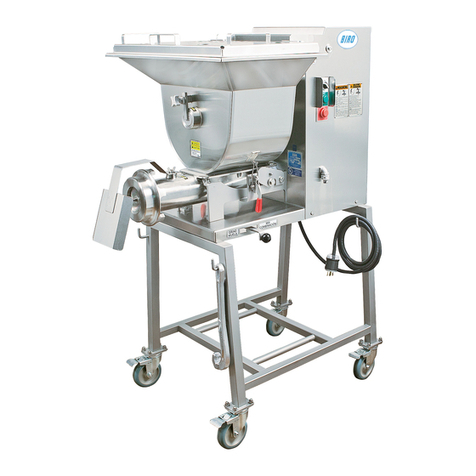
BIRO MINI-22 User manual

MINI-22-374
IMPORTANT NOTICE
This Manual contains important
safety instructions which must
be strictly followed when using
this equipment.
MODEL MINI-22
Automatic Feed Mixer Grinder
Operating Manual and Parts List


TABLE OF CONTENTS:
NOTICE TO OWNERS AND OPERATORS . . . . . . . . . . . . . . . . . . . . . . . . . . . . . . . . . . .
PAGE
SAFETY TIPS . . . . . . . . . . . . . . . . . . . . . . . . . . . . . . . . . . . . . . . . . . . . . . . . . . . . . . . . . . .
INSTALLATION . . . . . . . . . . . . . . . . . . . . . . . . . . . . . . . . . . . . . . . . . . . . . . . . . . . . . . . .
MOTOR WIRING AND ELECTRICAL REQUIREMENTS . . . . . . . . . . . . . . . . . . . . . .
PRE-OPERATION . . . . . . . . . . . . . . . . . . . . . . . . . . . . . . . . . . . . . . . . . . . . . . . . . . .
PARTS IDENTIFICATION . . . . . . . . . . . . . . . . . . . . . . . . . . . . . . . . . . . . . . . . . . . . .
OPERATION . . . . . . . . . . . . . . . . . . . . . . . . . . . . . . . . . . . . . . . . . . . . . . . . . . . . . . . . . . .
CLEANING . . . . . . . . . . . . . . . . . . . . . . . . . . . . . . . . . . . . . . . . . . . . . . . . . . . . . . . . . . . .
REMOVAL/INSTALLATION INSTRUCTIONS . . . . . . . . . . . . . . . . . . . . . . . . . . . . . . .
MAINTENANCE . . . . . . . . . . . . . . . . . . . . . . . . . . . . . . . . . . . . . . . . . . . . . . . . . . . . . . .
OPERATOR’S SIGNATURE PAGE . . . . . . . . . . . . . . . . . . . . . . . . . . . . . . . . . . . . . . . . .
WIRING DIAGRAM . . . . . . . . . . . . . . . . . . . . . . . . . . . . . . . . . . . . . . . . . . . . . . . . .
OPTIONAL PNEUMATIC FOOT SWITCH IDENTIFICATION . . . . . . . . . . . . . . . . . .
1
2
3
4
5
15
16
19 - 21
24
4 & 5
OPERATOR’S NOTES . . . . . . . . . . . . . . . . . . . . . . . . . . . . . . . . . . . . . . . . . . . . . . . . . . .
6 - 11
12
15
14
LIMITED WARRANTY . . . . . . . . . . . . . . . . . . . . . . . . . . . . . . . . . . . . . . . . . . . . . . . . . . 25
OPERATOR’S NOTES . . . . . . . . . . . . . . . . . . . . . . . . . . . . . . . . . . . . . . . . . . . . . . . . . . .23
OPERATOR’S NOTES . . . . . . . . . . . . . . . . . . . . . . . . . . . . . . . . . . . . . . . . . . . . . . . . . . .13
OPERATOR’S NOTES . . . . . . . . . . . . . . . . . . . . . . . . . . . . . . . . . . . . . . . . . . . . . . . . . . .18
THREE PHASE CONTROL PANEL. . . . . . . . . . . . . . . . . . . . . . . . . . . . . . . . . . . . . . . . 22

NOTICE TO OWNERS AND OPERATORS
BIRO’Sproductsaredesignedtoprocessfoodproductssafelyandefciently.Unlesstheoperatoris
properly trained and supervised, however, there is the possibility of a serious injury. It is the responsibility of
the owner to assure that this machine is used properly and safely, strictly following the instructions contained in
this Manual and any requirements of local law.
No one should use or service this machine without proper training and supervision. All operators should
be thoroughly familiar with the procedures contained in this Manual. Even so, BIRO cannot anticipate every
circumstance or environment in which its products will be used. You, the owner and operator, must remain alert
to the hazards posed by the function of this equipment, particularly the ROTATING GRINDING AUGER and
theROTATINGMIXINGPADDLE,whichcanseverelyinjureaninattentiveoperatoramputatingngersand
limbs. No one under eighteen (18) years of age should operate this equipment. If you are uncertain about a par-
ticular task, ask your supervisor.
This Manual contains a number of safe practices in the SAFETY TIPS section. Additional warnings are
placed throughout the Manual. Warnings related to your personal safety are indicated by:
OR
Warnings related to possible damage to the equipment are indicated by:
BIRO also has provided warning labels on the equipment. If any warning label, instruction label or
Manual becomes misplaced, damaged, or illegible, please contact your nearest Distributor or BIRO directly for
a replacement.
Remember, however, this Manual or the warning labels do not replace the need to be alert and to use
your common sense when using this equipment.
-NOTE-
“A copy of this manual is included with each MODEL MINI-22 MIXER GRINDER.
The descriptions and illustrations contained in this manual are not binding.
The manufacturer reserves the right to introduce any modication without updating
the manual.”
1

SAFETY TIPS
ROTATING GRINDING AUGER &
ROTATING MIXING PADDLE
TO AVOID SERIOUS PERSONAL INJURY
NEVER Touch This Machine without Training and Authorization by Your Supervisor.
NEVER Place Hands into Machine Input or Output Openings.
NEVER Open Machine During Operation.
ONLY Use a Qualied Electrician to Install According to Local Building Codes: Machine MUST
Be Properly Grounded.
ALWAYS Connect to Proper Voltage & Phase.
ONLY Install on a Level, Non-Skid Surface in a Clean, Well-Lighted Work Area Away from Children
and Visitors.
ALWAYS Lock Machine Casters After Moving This Machine.
NEVER Use This Machine For Non-Food Products.
NEVER Operate Machine With Product Mixer Safety Cover Opened, Removed, or Interlock Switch By-passed.
ALWAYS Turn Off, Unplug Machine From Power Source and Perform Lockout/Tagout Procedure to this
Machine BEFORE Attempting to Unjam or Unclog, Cleaning or Servicing.
NEVER Leave Machine Unattended While Operating.
NEVER Alter This Machine From its Original Form as Shipped From Factory. DO NOT Operate
Machine With Missing Parts.
PROMPTLY REPLACE Any Worn or Illegible Warning Labels.
ALWAYS Read Operation and Service Manual BEFORE Operating, Cleaning, or Servicing.
USE ONLY BIRO Parts and Accessories Properly Installed.
2

INSTALLATION
TO AVOID SERIOUS PERSONAL INJURY, PROPERLY INSTALL
EQUIPMENT IN ADEQUATE WORK AREA
ALWAYS Use Qualied Technician and Electrician for Installation.
ONLY Operate on a Solid, Level, Non-Skid Surface.
NEVER Operate Machine With Product Mixer Safety Cover Opened or Removed or Safety Switch By-Passed.
ALWAYS Connect to Proper Voltage & Phase.
ALWAYS Install Equipment in Work Area with Adequate Light and Space Away from Children and Visitors.
ALWAYS Lock Machine Casters After Moving Machine.
NEVER Bypass, Alter, or Modify This Equipment in Any Way From Its Original Condition.
NEVER Operate Without all Warning Labels Attached and Owner/Operator Manual Available to the
Operator.
UNCRATING AND SET UP
1. Read this Manual thoroughly before installation and operation. Do not proceed with installation and
operation if you have any questions or do not understand anything in this Manual. Contact your local
Distributor, or BIRO rst.
2. Remove all banding, shipping carton, and all equipment from inside the tub. Then take machine off
shipping pallet.
3. Install machine on a level, non-skid surface in a well-lighted work area away from children and
visitors.
4. This machine is complete except for knife and plate. There is a bowl shipping plug (cardboard) placed
in the output end of the grinding bowl to retain the grinding auger during shipment. REMOVE THE
BOWL SHIPPING PLUG AND THE GRINDING AUGER.
5. After checking and making sure the power supply is correct, plug in your machine.
NEVER OPERATE MACHINE WITH PRODUCT SAFETY COVER OPEN.
(Machine will not run with cover open or hopper removed.)
6.Machinemustbeproperlygrounded.Usequaliedelectriciantoinstallaccordingtolocalbuilding
codes.
3

MOTOR WIRING AND ELECTRICAL REQUIREMENTS
2. Connect leads to machine in a manner that will be approved by local electrical inspectors.
3. Rated voltage of the unit shall be identical with full supply voltage.
4. Voltage drop on the supply line shall not exceed 10% of full supply voltage.
5. The feederline conductor size in the raceway from the branch circuit to the unit must be correct to assure
adequate voltage under heavy starting and short overload conditions.
6. The feederline conductor shall only be used for the supply of one unit of the relevant horsepower. For
connections of more than one unit on the same feederline, a local electrician will have to be consulted to
determine the proper conductor size.
7. The size of the electrical wiring required from the power source to the Single phase mixer-grinder/chopper
is a MINIMUM OF No. 10 GAUGE WIRE.
8. The BIRO Manufacturing Company is not responsible for permanent wiring, connection or installation.
PRE-OPERATION AND AUGER ROTATION CHECK
ROTATION MUST ONLY BE CHECKED WITH THE
GRINDING AUGER REMOVED, otherwise serious irreparable
damage may occur to grinding components.
1. Turn the hand/foot selector switch to the hand position. Push the green start button. CHECK THE
ROTATION OF THE AUGER DRIVE SHAFT; ROTATION MUST BE COUNTER-CLOCKWISE as
indicatedbytherotationdecalafxedtothegrindingbowl.
2. If machine runs clockwise (backwards), it must be rewired to correct rotation, otherwise serious irreparable
damage may occur to the grinding components.
3. When supplied, check operation of optional pneumatic footswitch. Plug footswitch cord into female
coupling located on the same side as the operation controls. Move selector switch to foot. The machine will
operate with pressure on the footswitch bellow. Releasing the bellow stops the machine. The footswitch
operates the mix and grind together.
4. Insert auger assembly into grinding bowl, place knife (sharp edges out) onto the square end of the auger
assembly. The breaker plate slides over the worm knife drive pin, and is held from rotating by pins in the
grinder bowl. Install the retaining ring.
4
Three phasegrindersarewired208/220voltsunlessotherwisespecied.Besuremotorspecications
(voltage,cycle,phase)matchpowersupplyline.Besurevoltageisuptospecication.
The size of the electrical wiring required from the power source to the Three phase mixer-grinder/chopper
is a MINIMUM OF No. 12 GAUGE WIRE.
1. Single phasegrindersarewired208/220voltsunlessotherwisespecied.Besuremotorvariable
frequency drive parameters are adjusted for correct line voltage. Be sure to read line voltage for correct
parameter adjustment. See variable frequency drive manuals for parameter settings.
5. Check placement of all warning labels and be sure anyone who is to operate this MINI-22 MIXER
GRINDER has read and fully understands the operators manual. Machine is now ready for trained operators
to process product.
6.Usemeatdeectorattachedtogrindingbowltoeliminatemeatsplatter.
7. Contact your local distributor if you have any questions or problems with the installation or operation of this
machine.
5
OPERATOR’S NOTES
ONLY HAND TIGHTEN RETAINING RING
For best results, use knife and plate as a set. Do not operate machine for any
period of time without product in the grinding bowl. This will cause
heating and dulling of the knife and plate.

PARTS LOCATION
64040
Hopper Cover
64009
Hopper Assembly
53852
Paddle Lock
Arm Assembly
64001
Grinder Bowl
64048
Spurt Guard
A64041
Cart Assembly
PC175-1
Caster
64037
Hood Assembly
56300J-CPB
Female
coupling
metal type
Single phase
241-3-10
POWER
CORD
10-3
CR22S
Bowl Ring
Controls
see page 7
6
HNM46S
Hex Nut
2- Required
Three phase
241-4
POWER
CORD
12-4
64044
Bowl Mounting Stud
2- Required
64038
Rear Cover Panel
(NOT SHOWN)

64026
Lid Limit Switch
Located Inside Hood Assembly
Upper Left Side
7
Mini-22
Controls
42MC-Y73
Mix Start Button
42MC-Y74
Stop Button
42MC-Y73
Grind Start Button
64029 (Single Ph)
Hand/Foot
Selector Switch
EMG90668 (Three Ph)
Hand/Foot
Selector Switch
Hand/Foot
Selector Switch
Phase Specic

Mini-22
Single Phase
8
64027
Auger Motor, 2HP
64028
Mixer Motor, 1HP
64024-1
Mixer Variable
Frequency Drive
64023-1
Grinder Variable
Frequency Drive
56300R
Air Switch Grinder
56300R
Air Switch Mixer
64029
Hand/Foot
Selector Switch
See page 7
64050
V-Seal
64042
Mixer Drive Shaft Coupling
64050
V-Seal
64015
Auger Drive Shaft Coupling
64025
Main Disconnect
Switch, 40 Amp
Single Phase Only
H653-E
Warning Label
English
H653-SP
Warning Label
Spanish
BES16971
Risk of Electrical
Shock
VTS622
Label/ Turn Off Power
64022
Side Panel Cover
Single Phase Only
64044
Bowl Mounting Stud
2- Required
64024
Mixer Variable
Frequency Drive
(Used up to s/n: 73113)
64023
Grinder Variable
Frequency Drive
(Used up to s/n: 73113)
64023-1
Grinder Variable
Frequency Drive
(s/n: 73114 and up)
64024-1
Mixer Variable
Frequency Drive
(s/n: 73114 and up)

9
Mini-22
Three Phase
64046
Side Panel Cover
Three Phase Only
H653-E
Warning Label
English
H653-SP
Warning Label
Spanish
BES16971
Risk of Electrical
Shock
64027
Auger Motor, 2HP
64028
Mixer Motor, 1HP
56300R
Air Switch
EMG90668
Hand/Foot
Selector Switch
See page 7
64050
V-Seal
64042
Mixer Drive Shaft Coupling
64050
V-Seal
64015
Auger Drive Shaft Coupling
64044
Bowl Mounting Stud
2- Required

63136
Paddle Spacer
63073-2
Curved Mixing
Paddle
53852
Lock Arm Bushing
64009
Hopper
A64002
Auger Assembly Complete
CK22
Knife Drive Pin
10
HHSM015S
Hex Head Screw
3- Req’d
64013
Retaining Ring 64014
Auger Drive Seal
63073
Round Mixing
Paddle
64040
Hopper cover
53783
Decal, Rotation

CR22S
Bowl Ring
Note- Hand tighten only
64048
Spurt Guard
CP22
Bowl Pin
HNM46S
Hex Nut
2- Required
Uses 19mm Wrench
64048-1
Spurt Guard,
Thumb Screw
64036
19mm Wrench
For Bowl Fasteners
11
64001
Grinder Bowl
53783
Decal, Rotation

12
PNEUMATIC FOOT SWITCH COMPONENTS
Part No.
56300BEL
DESCRIPTIONS
56300C
56300K-CPB
56303
56304
HHS004S
HN05S
LW03S
Bellow, Replacement
Guard Only
CPB Coupling Metal Body-Male
Foot Switch w/Male Coupling
Foot Switch Assembly Complete
Hex Head Screw, #8 - 32 x ⅜
Hex Nut #8 - 32
Lock Washer #8
OPTIONAL
PNEUMATIC FOOT SWITCH COMPLETE
56304

13
OPERATOR’S NOTES

OPERATION
ROTATING GRINDING AUGER &
ROTATING MIXING PADDLE
TO AVOID SERIOUS PERSONAL INJURY
NEVER Operate Machine With Product Mixer Safety Cover Opened or Hopper Removed or Safety
Switch By-Passed.
ONLY Properly Trained Personnel Should Use This Equipment.
NEVER Place Hands Into Machine Input or Output Openings.
NEVER Open Machine During Operation.
DO NOT Wear Gloves While Operating.
DO NOT Tamper With, Bypass, Alter, Or Modify This Equipment in Any Way from Its Original Condition.
ALWAYS Turn Off and Unplug Machine from Power Source and Perform Lockout/Tagout Procedure to This
Machine Before Unjamming, Unclogging, Cleaning or Servicing, or When Not in Use.
NEVER Leave Machine Unattended while Operating.
NEVER Operate Without All Warning Labels Attached and Operating Manual Available to the Operator.
A. TO PROCESS PRODUCT
1. Before starting the mixer-grinder, have a container for receiving ground product at the output end of the
grinding bowl.
2. FIRST GRIND
3. SECOND GRIND - If required, change breaker plate.
4. When grinding process is complete, unplug machine from power source and perform lockout/tagout
procedures. Proceed to cleaning.
a. Fill product hopper (maximum 45 pounds), and close Product Mixer Safety Cover.
b. With the hand/foot selector switch in hand position, push the green mixer start button. Next press green
grinder start button. It is recommended to use a breaker plate with a 3/8” diameter or larger holes.
c. When all product has been ground out press red stop button.
a. Fill product hopper (maximum 45 pounds), and close Product Mixer Safety Cover.
b. With the hand/foot selector switch in hand position, push the green mixer start button. During the mix
operation seasonings may be added through the sight holes in the hopper cover.
c. After the desired mix, press green grinder start button.
d. When all product has been ground out press red stop button.
14
DO NOT Grind Frozen Product.

15
CLEANING
BEFORE CLEANING OR SERVICING
ONLY Use Recommended Cleaning Equipment, Materials, and Procedures.
NEVER Spray Water or Other Liquid Substances Directly at Motor, Power Switch or any Other
Electrical Components.
ALWAYS Thoroughly Clean Equipment at Least Daily.
ALWAYS Turn Off and Unplug Machine from Power Source and Perform Lockout/Tagout Procedure to This
Machine Before Cleaning or Servicing.
CLEANING THE MINI-22 MIXER GRINDER
1. Disconnect mixer grinder from power source and perform lockout/tagout procedures.
2. Remove end ring, breaker plate, knife and grinding auger.
3. Remove mixing paddle, bowl and hopper from the machine (see page 15 for procedures).
4. Machine is now ready to be cleaned using warm soapy water and rinsed with clean water. Machine may be
cleaned by power spray washing, taking care not to spray directly at any electrical controls.
5. After machine has been cleaned and allowed to air dry, all exposed metal surfaces should be coated with a
good food grade light oil or grease.
REMOVAL/INSTALLATION INSTRUCTIONS
PADDLE REMOVAL:
Open hopper cover, loosen the paddle lock thumb screw(thumb screw located at front of hopper). While
holding mixing paddle, turn lock arm clockwise, and remove lock arm from hopper. Next remove paddle
drive end from square drive. Then remove paddle from hopper.
PADDLE INSTALLATION:
Install paddle drive end into square drive. Holding mixing paddle, align paddle shaft to the lock arm. Slide
lock arm into hopper onto the shaft. Turn counterclockwise to lock position. Tighten thumb screw.
BOWL/HOPPER REMOVAL:
Remove ring, breaker plate and knife. Auger can now be pulled out from grinding bowl. Using 19mm
wrench,loosenandremovebothhexnutsfrombowlange.Removebowlbypullingawayfromhopper
studs. Remove hopper from frame by pulling from front of machine.
BOWL/HOPPER INSTALLATION:
Install hopper onto frame, slide back into position. Install bowl onto the hopper studs, install and tighten hex
nuts to secure bowl. Slide the auger into bowl, install knife, breaker plate and ring.
Note: Ring is to be hand tightened only.

16
MAINTENANCE
NEVER Touch This Machine Without Training and Authorization By Your Supervisor.
USE ONLY GENUINE BIRO Parts and accessories Properly Installed.
PROMPTLY REPLACE Any Worn or Illegible Warning Labels.
ALWAYS Turn Off and Unplug Machine from Power Source and Perform Lockout/Tagout Procedure to This
Machine Before Cleaning or Servicing.
ROTATING GRINDING AUGER &
ROTATING MIXING PADDLE
TO AVOID SERIOUS PERSONAL INJURY
NEVER Place Hands Into Machine Input or Output Openings.
NEVER Bypass, Alter or Modify This Equipment in Any Way From Its Original Condition.
GENERAL:
Check all fasteners for tightness. Replace any missing fasteners.
Check all tags and labels. They must be legible. Replace if required.
Check casters. They must roll freely and lock in place. Replace if required.
Check lid alignment. It should sit evenly on top edge of hopper. Correct if required.
Open and close lid. There should be some resistance, lid should lower slowly.
Check removable hopper appearance. Fix any damage if required.
Check seal and seal retainer located on removable hopper. Correct if required.
Check mixing paddle for damage. Be sure it does not rub inside of hopper. Correct or replace if required.
Check bowl, auger, knife drive pin and ring for any damage. Replace if required.
Check control switches they must be in good working order. Replace if required.
Check pneumatic foot switch for damage. Fix or replace if required.
MOTOR GEAR DRIVES:
Both the mixer and grinder motor gear drives are totally enclosed. They are lubricated and sealed from the
manufacturer. They do not require any maintenance or lubrication changes.
ALWAYS Turn Off and Unplug Machine from Power Source and Perform Lockout/Tagout Procedure to This
Machine Before Cleaning or Servicing.
ALWAYS Use Qualied Technician and Electrician for Maintenance.
Check power cord for any damage. Repair or replace if required.
ELECTRICAL COMPONENTS:
Check all electrical connections for tightness.
If any access panels have been removed, they must be re-sealed with an NSF listed sealant.
Check all control switches for tightness.
Check lid limit switch for proper operation and tightness.
ELECTRICAL MAINTENANCE

17
DO’s DON’Ts
• Always keep knife & plate as matched set.
• Always keep the knife & plate sharp.
• Always install the knife & plate in correct
sequence, knife 1st, then plate.
• Always inspect the plates making sure all holes
are clear - that there are no cracks.
• Always keep knives & plates lubricated in storage
and when starting machine.
• Always check for straightness by laying the knife
on the plate before inserting in machine.
• Always use coolant when sharpening plates.
• Never, never mix different knives to different plates.
• Never, never over tighten the bowl retaining ring
on the machine.
• Never, never hit the plate against anything to
clean the holes.
• Never, never run the grinder without product.
Product is a natural lubricant. Heat can build up so
fast that cold product could crack the plate.
• Never, never throw the knives & plates.
GRINDER KNIVES & PLATES
SAFETY
Always inspect parts for cracks, heat fractures, discoloring. Never run on parts that have these defects.
Always use O.S.H.A. lockout tagout procedures when changing knives and plates!
Always wear gloves when handling knives and plates.
Never run plates below minimum thickness.
Customer is responsible for safety, installation, and operation of equipment. It is the responsibility of the user to
comply with all O.S.H.A. or A.P.H.I.S. regulations.
IMPORTANT!
USE KNIFE AND PLATE TOGETHER
Always use the same knife and plate together. If one
has gradually worn away from perfect level, the other
will have worn with it. As a result they may still be
used together. If however, one is matched with a
different member which is ground true, the set will
certainly not turn out a good product. In addition, such
practice will probably break the new member.
Available Grinder knives and plates for Model Mini-22
Knife, Size 22, Standard Disposable MC22-17
Plate,Size22,⅛”(3,5mm)diameterholes MC22-18-125
Plate, Size 22, 5/32” (4,0mm) diameter holes MC22-18-156
Plate, Size 22, 3/16” (5,0mm) diameter holes MC22-18-187
Plate,Size22,⅜”(9,0mm)diameterholes MC22-18-375
Table of contents
Other BIRO Grinder manuals

BIRO
BIRO AFMG-48-II Service manual

BIRO
BIRO Mini-32 Service manual

BIRO
BIRO AFMG-48-II Service manual

BIRO
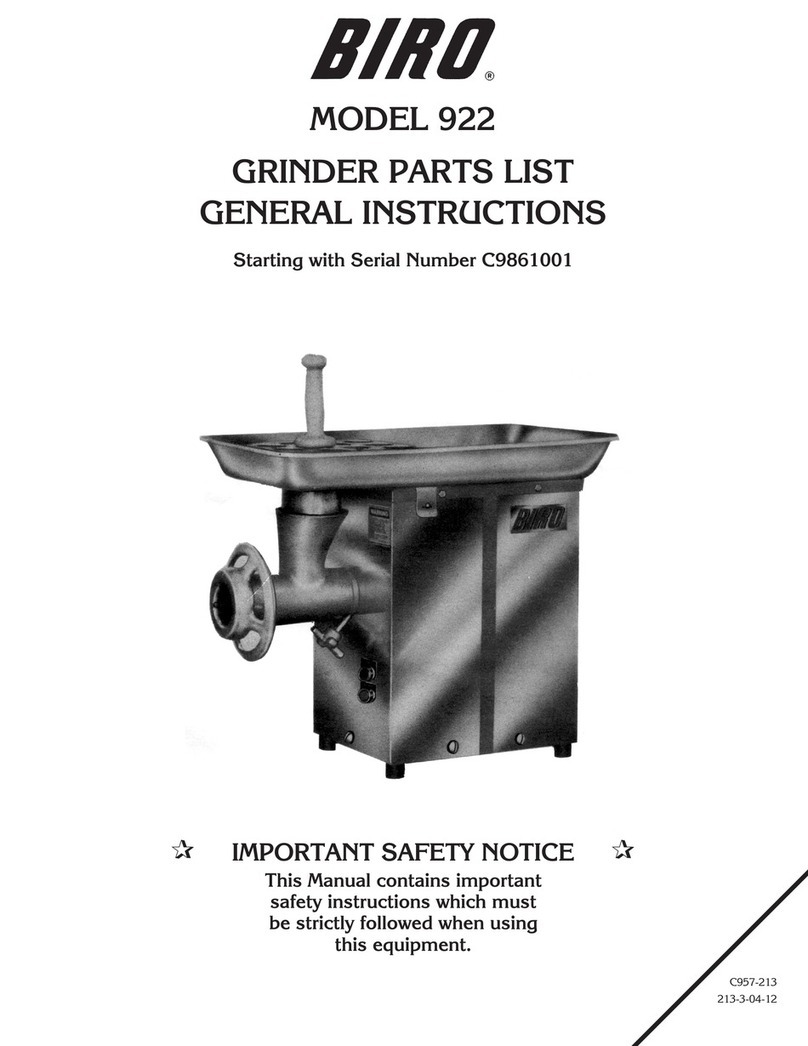
BIRO 922 Instruction manual

BIRO
BIRO AFMG-52 Service manual

BIRO
BIRO AFMG-48-II Service manual

BIRO
BIRO AFMG-52 Service manual

BIRO
BIRO 722 Operation manual

BIRO
BIRO 8-12 Operation manual

BIRO
BIRO Mini-32 Service manual