Bism JA Series User manual

1
JA(Air)
BC
OPERATION
MANUAL
Instruction
Thank you for purchase of our product.
This operating manual is the guidebook to provide instructions
on how to use your buoyancy compensator (B.C.), Air, for
recreational diving.
We believe this manual is useful in mastering technology of a
B.C. for people who have learned the right usage of a B.C.and
obtained a C-card through proper training at a diving
instruction organization as well as people who use it at C-card
training. Please carefully read and digest the contents of this
manual before use. We also suggest that you take this manual
with you to refer to before diving.
Keep this manual in a safe place. If you lose it, contact your
original dealer or authorized distributor of our company. A
replacement manual will be reissued later.
The main contents consist of assembly of B.C., setting to a
tank, the check before use, usage, care after use, storage, and
a periodic inspection.
B.C. Air is diving gear to use in combination with a regulator for
recreational diving. Therefore, the knowledge of the right
handling of regulator is also necessary. Please use the
operating manual of the regulator which you use as well as this
manual of Air.
In addition, depending on the model of regulator, it is
considered not being suitable for the use by the combination
with this product. We recommend you use by the combination
with the regulator made by Bism.
We are constantly researching and improving our B.C., and so
the product you purchased may differ in certain details from the
one described in this manual. If you have any queries
regarding your B.C. or the information contained in this
manual, please feel free to contact our company at the address
below.
Bism CORPORATION
5F, 3-6-18, Higashinihonbashi, Chuo-ku, Tokyo 103-0004 Japan
Phone: +81-3-5640-8126 Fax: +81-3-5640-8131
Introduction・・・・・・・・・・・・・・・・・・・・1
Important Information・・・・・・・・・・・・・・・・2
Precautions・・・・・・・・・・・・・・・・2
Name of parts ・・・・・・・・・・・・・・・・・・・・3
Special Features & Specifications・・・・・・・・・・4
Assembly・・・・・・・・・・・・・・・・・・・・・・5
Before Setting to a Tank・・・・・・・・・・・・・・・6
Setting to a Tank・・・・・・・・・・・・・・・・・・7
Installation of B. C. Hose・・・・・・・・・・・・・・7
Basic Operation of Air Supply・Exhaust & Actuation Check・8
Put on・Take off・・・・・・・・・・・・・・・・・・10
Basic Usage・・・・・・・・・・・・・・・・・・・・・11
2 Way Inflator・・・・・・・・・・・・・・・・・・・12
Strage Pocket・・・・・・・・・・・・・・・・・・・12
Remove a B. C. from a Tank・・・・・・・・・・・・・・13
Wash & dry・・・・・・・・・・・・・・・・・・・・・13
Storage, Periodic Inspection & Service after the Sales・14
Troubleshooting・・・・・・・・・・・・・・・・・・・15
CONTENTS

2
IMPORTANT INFORMATION
In order to use B. C. safely, the right operation, periodical maintenance and check are indispensable. Carefully read the advice on
safety given in this manual before diving.
As the indication in this manual and to the product, in order to use the product safely and correctly, and to prevent the danger and the
damage to the property of you or other people beforehand, various marks are used.
The indication and the meaning are as follows.
PRECAUTIONS
Purpose of Use
This product is diving gear for recreational diving use.
The connection with a regulator allows the use and is buoyancy compensator “adjusting neutral
buoyancy” at the time of recreational diving.
Danger
●Use this product after having obtained a C-card and completing a proper training program at an internationally recognized diving
school, and be familiar with diving gears, or under the instruction of the diving school. Otherwise it may cause an accident resulting
in injury or death.
●Please be sure not to dive alone by any means, but to respect buddy system. Single diving may lead to a serious accident and is
very dangerous.
●Please be sure to recognize all the handling method, the warning and the instructions with this manual before using this product. In
addition, please use it in the ocean after understanding how to use.
●Do not use this product for any purpose other than recreational diving. In particular, please do not use it as a lifesaver or a float. Air
may fall out and it may cause to be drowned.
●If this product starts to function abnormally, stop use immediately and consult with your original dealer or authorized distributor of
our company.
Warning
●When you perform scuba diving, please carry out by good health condition. When you feel uneasy in condition, please do not push
yourself and stop diving.
●Before performing scuba diving, please avoid to take alcohol and medicine, and the one who is in bad physical condition or with a
chronic disease should see a doctor for diagnosis in advance.
●This product is designed on the basis of a general healthy person who has average physical strength. Divers need to plan and
execute a safe diving which suited for them, respectively.
●Please do not put weight into a side pocket. Not only it causes the trouble of the pocket, but also it becomes difcult to remove
weight in emergency and may cause an accident resulting in injury or death.
●Please adjust the weight so that you can keep the neutral buoyancy on the surface while being in the state that air is exhausted
completely from a oat before diving. It may cause an accident resulting in injury or death by uncontrolled descent.
●Please do not fold or pull a hose. It not only breaks, but it may cause an accident resulting in injury or death.
●Please do not carry out usage that you ascend by using the buoyancy of the air supplied as a lifting bag. You may get decompres-
sion sickness by rapid ascent.
●Please do not jump from the high place more than 2m in the state that air is in the air cell. As big buoyancy is applied rapidly, not
only B. C. breaks, but it may carry out an injury.
Danger
Danger indicate a great risk of death or serious injury from improper use.
Warning
Warning indicate a risk of death or serious injury from improper use..
Caution
Caution indicate a risk of minor injury or damage to property from improper use.
[ Note ] Useful Information to know.
Caution
●If various solvents such as gasoline, spray liquid and cleaner such as cosmetics, and acid and alkali adhere, deterioration may
be occurred. Please be careful enough so that these do not attach to the body and a hose.
●Please use B. C. of the size which fits your body type. Otherwise, you may lose balance in the water and it causes a decrease
in performance.
●Though the product can withstand the shock in the usual use, drops and hard knocks may damage it.
●In the case of wearing to the bare skin, weak skin and the allergic tendency may get a rash. When you get a rash, stop wearing
of the B. C., and consult with a medical specialist of dermatology.
●Since it may become a safety problem, please do not modify the product. Responsibility cannot be taken about the trouble after
modification.

3
カマーベルト
ショルダーバックル
ホ-スリテーナ
チェストベルト
メインハーネス
ランバーサポート
ソフトバックパッド
フロート
タンクヘッドベルト
アンダーリリーフバルブ
エクゾーストノブ
ブランケット
タンクベルト
ショルダーリリーフバルブ
ショルダーバックル
Dリング
エクゾーストノブ
ブランケット
ハンドルベルト
ストレージ・ポケット
B-POSITION
インフレーター
NAMES OF PARTS
At the Time of Assembly
■JA3620
Hose Retainer
Float
B. C. Hose Holder
Whistle
Side Pocket
Shoulder Belt
D-ring
Exhaust Knob
Waist Buckle
Waist Belt
Cummerbelt
Hose Clip
Strage Pocket
Inflator
Inflator
Handle belt
Tank head belt
Chest belt
Tank belt
B-POSITION
Shoulder Buckle
At the Time of Buckle Release / Back and Other.
■JA3610 ( The name of each parts is the same in other models.)
Hose Retainer
Soft back pad
Float
Shoulder OPV
Under OPV
D-ring
Exhaust Knob
Housing
Housing
Exhaust Knob
Cummerbelt
Strage Pocket
Inflator
Shoulder Buckle
Main harness
Lumbar support
Shoulder Buckle

4
For OCT2, please refer to the separate instruction manual.
NAMES OF PARTS
■Standard Valve
Housing
“IN” Button
“OUT” Button
Nose
Housing
“IN” Button
“OUT” Button
“ORAL” Button
Nose
■Combination Valve Ⅱ
Inflator
Attachments
Please confirm before using this product. Refer to the page in ( ) for the detailed explanation.
■B. C. Hose (1 piece), Hose Guard (1 piece).
Connect to a regulator first stage. (Page 5)
■Operating Manual (1 copy)
MAIN FUNCTIONS & FEATURES
Special Features
■Adoption of Quick Release Shoulder Buckle. (Page 9)
The quick release buckle which can easily loosen a
shoulder belt with only a thumb is adopted.
■H. f. s. Float Structure is Adopted.
When air is supplied to a B. C., the float structure which
inflates so that the body may be wrapped in by the
effect of a special shape rib is adopted.
■Adjustment Mechanism of Cummerbelt Length (Page 6)
●Cummerbelt length at the waist portion is adjustable.
■Long Tank Buckle (Page 6)
The long tank buckle which you can fix to a tank without
particular strong power is adopted.
■Easy Exhaust Operation (Page 8)
●The exhaust, power deflation, by the “OUT” button can
be performed.
●The exhaust by the “ORAL” button is possible.
●When exhaust knob of a shoulder belt portion is
pulled, the exhaust, quick deflation, from relief valve
of a right shoulder can be performed.
●When remote control portion of the inflator is pulled,
the exhaust from housing of a left shoulder, pull dump
deflation, can be performed. (Standard valve only)
●When exhaust knob of a right waist portion is pulled,
the exhaust, quick deflation, from relief valve of a
right waist is possible.
■Adoption of Thin Harness.
The newly-designed thin harness which distributes
weight appropriately by bringing a tank close to your
body is adopted.
■2 Way Inflator is Adopted. (Page 13)
The 2 way inflator system which can also turn a
corrugated hose from the back side to use is adopted.
■Adoption of Waist Curve Line.
The waist curve line which fits the body easily by
making a curve around the waist is adopted.
■Adoption of Strage Pocket. (Page 12)
Function of functionality and design that suits the diver's
style. This is a new strage system designed for ease of
use.
■Adoption of B-POSITION (Page 12)
The B-POSITION installed on the left and right is
effective for the back position of the 2WAY inflator and
in holding the octopus.

5
MAIN FUNCTIONS & FEATURES
Specifications
Body
The maximum buoyancy: XS: 117N (12kgf), S: 137N
(14kgf),M: 157N (16kgf), L: 196N (20kgf)
Weight: XS:2.7kg, S:2.8kg, M:2.9kg, L:3.0kg
Length of beltline ; 55 cm - 100 cm
Temperature range ; -5 - +50℃
Material: Thermo-plastic coating cloth
Basic cloth: Nylon
Back side: Polyurethane
Hose Portion
Material: Inner tube ; Vinyl chloride
Outer cover ; Vinyl chloride
Coupling ; Copper alloy
Outer diameter ; 13 mm
Hose length ; 700 mm
Nominal size of coupling threads ; 3/8-24UNF
Maximum operating pressure ; 15 bar
Minimum bending radius (Inside of hose) ; 115 mm
Hose guard ; Regular equipment
Standard Valve
Corrugated hose length: 540 mm
(Length from the center of housing to the end of an oral button)
Weight: 366 g
Air supply flow: 100 liter/minute
Combination Valve Ⅱ
Corrugated hose length: 550 mm
(Length from the center of housing to the end of an oral button)
Weight: 394 g
Air supply flow: 80 liter/minute
Relief Valve
Position: One in right shoulder, one in right waist portion.
Exhaust operation pressure at the time of over pressure:
0.2 bars or less.
Tensile force necessary for quick deflation:
9.8 - 14.7 N (1 - 1.5kgf)
Float Explosion Prevention Equipment
■Relief Valve
When air has been supplied to float of B. C. excessively by
mistake, in order to prevent the burst, if internal pressure of
float exceeds certain pressure, it is in structure to open the
relief valve automatically and release air from housing.
Warning
●Please install the hose in the state that the first stage of a
regulator is not connected to a tank. If the first stage is
pressurized during work, a plug in the port flies and it is
dangerous.
●Please use the regulator with the first stage having L. P. port
thread of 3/8-24UNF as nominal size. Otherwise, not only it
causes the damage of equipment, but
also a hose comes off and it may cause
an accident resulting in injury or death.
●Please confirm that O-rings are set at
the threads portion of each B. C. hose.
When there are no O-rings, it causes the air leakage.
●Do not install the B. C. hose to an H. P. (High Pressure) port.
Install B.C. Hose to a Regulator
ASSEMBLY
Caution
●When you tighten hose couplings with a spanner, please
keep the tightening torque of 9.8N/m (100kgf/cm).
Otherwise it may cause to damage the threads portion.
●Please do not attach hose guards other than our products
to a B.C. hose.
Please remove the plug from the L. P. (Low Pressure)
port of the first stage of a regulator.
1
Please screw in the coupling of a B. C. hose to L. P. port
and turn it clockwise with a spanner to tighten it.
Tightening torque is 9.8 N / m (100 kgf / m).
2
[ Note ]
○If you are not familiar with the installation work, please
ask your original dealer or the authorized distributor of
our company for installation of hoses.

6
1
23
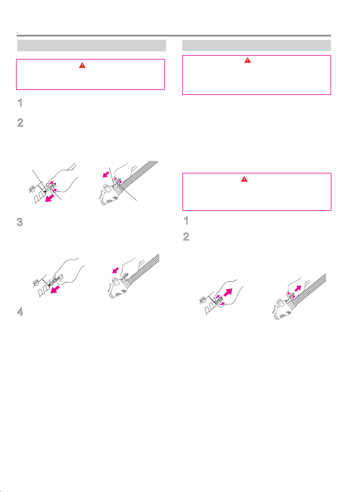
Adjust Cummerbelt Length
Warning
●Please do not remove Velcro tape which connects harness and
a side belt, and do not change width of the Velcro tape portion.
●Please wear your own diving suit and perform the length
adjusting.
1
2
□Shorten the length.
Take off soft back pad.
Remove the Velcro tape of a cummerbelt.
BEFORE SETTING TO A TANK
Check of B.C. Hose
Please check whether the hose is damaged or has broken.
Warning
●If there is an abnormality in your B. C. hose, you must not
use it.
●When there is an abnormality, stop to use it and contact
your original dealer or authorized distributor of our
company.
3Pull out the belt as much as you want to shorten it.
At this time, please be careful for the Velcro tape “Male”
not to protrude from the Velcro tape “Female” by pulling
out too much.
Velcro tape “Male”
4Press down the Velcro tape from the front and back side
and stick together.
Velcro tape “Female”
5Install the soft back pad.
□Lengthen the length.
Please perform like “1” and “2” of "Shorten the length",
and send a belt to the direction to lengthen in “3”. At this
time, be careful for the Velcro tape "male" not to enter into
the slit of harness by sending it too much.
Stick the Velcro tape together like in “4”, and install the
back pad like in “5”.
1
2
[ Note ]
○A waist size changes a lot with the kinds of suit to wear.
When the diving suit to wear is changed, please be sure to
readjust the length.
○A cummerbelt is in each side of right and left. Please
perform length adjustment for both cummerbelt.
SETTING TO A TANK
Handle Belt.
Belt Pad. Harness.
Tank Buckle.
Slide..
Slide.
Install B.C. to a Tank
Slide a tank buckle and a belt
pad in right and left over the
belt so that their position may
become close to the harness
side. Pass a tank belt through
the 2 slits of a tank buckle as
shown in a figure, and make a
tank belt ring large enough for a
tank goes through.
1
Figure showing
the way to pass
the belt.
[ Note ]
○A handle belt is a handle for carrying the whole tank,
after setting B. C. to a tank.
Warning
●Please put the tank on the stable place, such as the flat
ground, at the time of setting. It is dangerous if it falls.
●Please be careful not to catch a handle belt between a
tank and B. C. at the time of setting. Not only you cannot
use a handle belt, but also a tank is not fixed firmly.
[ Note ]
○Install a B. C. to a tank before setting a regulator first
stage.
In the state that a tank buckle is
set in direction of a figure, pull
the end portion of a belt, and
tighten a tank.
While pulling the end of the
belt, turn the tank buckle.
Stick the end of the belt to the
Velcro portion of the belt.
Having a tank belt, move it up
and down and check whether
the tank belt moves. If it
moves, please start it again
from the beginning.(Refer to
page 17 for the way to
remove.)
Put the ring of a tank belt over the
top of the tank. Set a direction of a
tank so that the air exit side of a
tank valve may turn to the back side
at the time of wear.
Also, adjust the setting height of
B.C. so that a tank head belt may
be fixed at the lower portion of a
tank valve in the level state, and
then tighten it.
Be careful not to tighten a tank
head belt too much at this time.
2
5
4
3
Handle Belt.
Make a tank head belt
level.
7
■JA3610
(Combination Valve)
■JA3620
(Standard Valve)
1
2
3
4
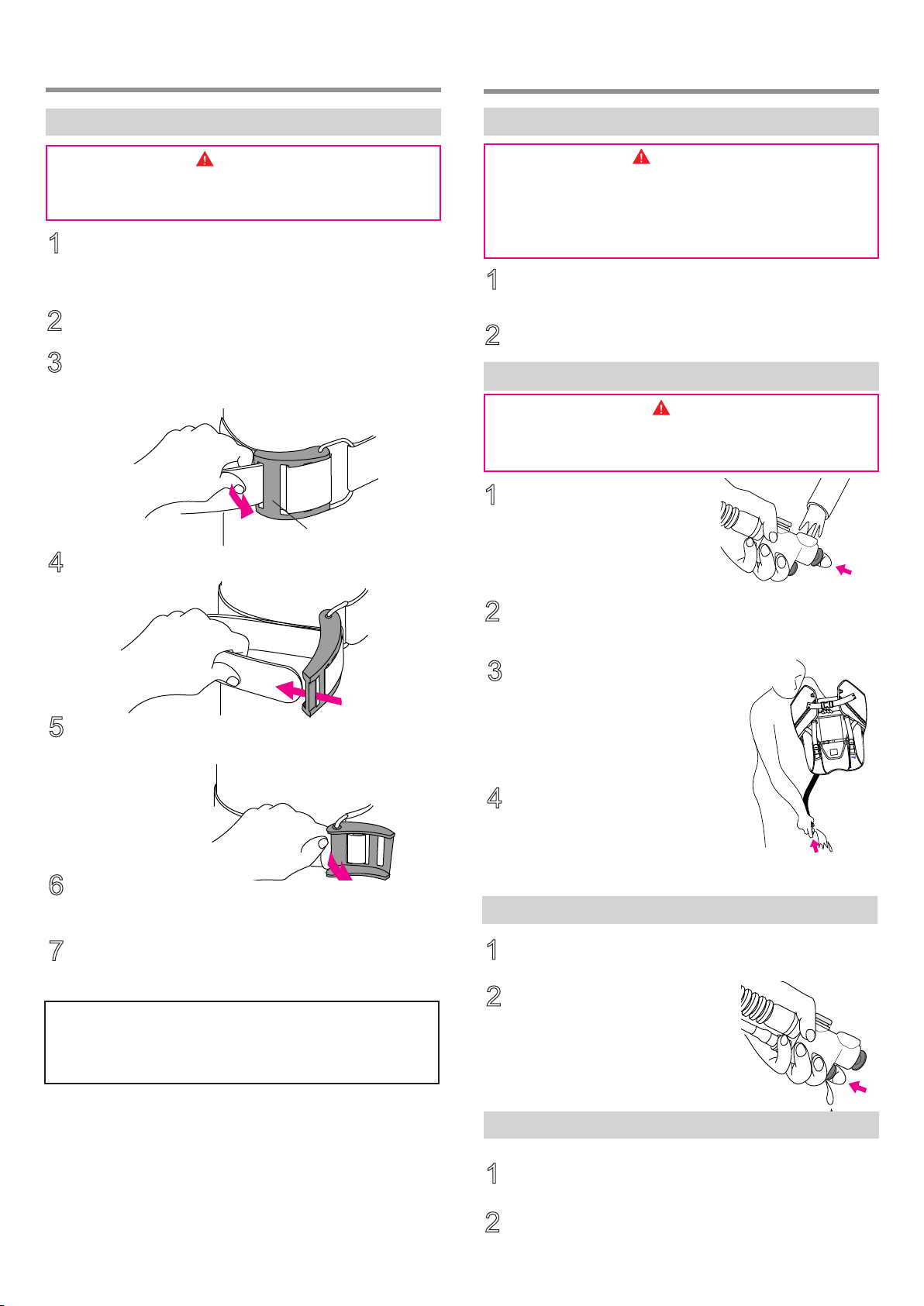
Install a B.C. Hose
INSTALLATION OF B.C. HOSE
Warning
●When you perform the connecting work of a B. C. hose,
close the tank valve, push the purge button of a regulator
to release the pressurized air in a hose.
Install a regulator first stage to tank valve according to
an operating manual of the regulator.
Connect a quick-coupler at the end of a B. C. hose to a
nose while sliding a collar of the quick-coupler.
Grip the end of the quick-coupler and push it until it
sounds "click".
While pulling the quick-coupler by gripping the end of it,
check whether it comes off.
When it comes off, please start it again from the
beginning.
Nose
Collar
Nose
Collar
■JA3610
(Combination Valve)
■JA3620
(Standard Valve)
1
2
Check the Connecting Portion of B.C. Hose
Open a tank valve according to an operating manual of a
regulator or a gauge. Touch the connecting portion with your
fingers to check if air leaks or not. Also, check if you can
hear the sound of air leakage,
If air leaks, once disconnect the quick-coupler and connect it
again from the beginning after pushing a purge button of a
regulator second stage to release air pressure in a hose,
and then check air leakage again.
Warning
●If there is an air leakage from a connecting portion, do
not use it.
●When the air leakage from a connecting portion does not
stop, please consult with your original dealer or
authorized distributor of our company.
□Disconnect B.C. hose.
Warning
●Before disconnecting a quick-coupler of B.C. hose from
inflator, be sure to close the tank valve, push the purge
button of a regulator to release the pressurized air in a
hose.
Pull the collar of a quick-coupler at the end of a B. C.
hose and disconnect from the nose while pulling the
collar.
Close the tank valve, push the purge button of regulator
second stage to release residual air in a hose.
■JA3610
(Combination Valve)
■JA3620
(Standard Valve)

8
“Power Inflation”
When you push “IN” button,
air is supplied in the float.
Check whether air is supplied
in float only while pushing the
button.
“Oral Inflation”
Hold a mouthpiece of an
inflator in your mouth firmly, if
you push oral button only
while blowing a breath, air is
supplied into a float. Check
whether air is supplied
certainly.
■Air supply operation
■Exhaust operation
[ Note ]
○Please refer to Page 11 for underwater exhaust operation.
“Deflation by ORAL Button”
When “ORAL” button is
pushed, the valve in the
inflator will be released and
the air in float will fall out
through the mouthpiece. Put
air in a float about 80% and
check whether air is exhausted
only while you push the
“ORAL” button.
"Pull Dump Deflation"
Pulling down the inflator body
will release the valve in the
shoulder housing and let the
air in the float exhaust. Put air
in a float about 80% and check
whether air is exhausted only
while you pull the inflator.
“Power Inflation”
When you push “IN” button, air is
supplied in the float. Check
whether air is supplied in float
only while pushing the button.
“Oral Inflation”
Hold a mouth piece of an inflator
in your mouth firmly, if you push
oral button only while blowing a
breath, air is supplied into a float.
Check whether air is supplied
certainly.
■Air supply operation
■Exhaust operation
Warning
●Exhaust by the “OUT” button is
performed only when an inflator
is set up correctly and air is in
a tank. Air is not supplied
when there is not enough air.
●Please do not pull combination
valve. It causes of breakage and
also operation failure.
[ Note ]
○If you perform the exhaust with the “OUT” button (Power
Deflation), a little air will be exhausted from the root of the “OUT”
button, but it is not failure.
○Please refer to Page 11 for underwater exhaust operation.
“Power Deflation”
When “OUT” button is pushed,
the valve in the housing on a left
shoulder will be released and the
air in float will fall out. Put air in a
float about 80% and check
whether air is exhausted only
while you push the button.
“Deflation by ORAL Button”
When “ORAL” button is pushed,
the valve in the inflator will be
released and the air in float will fall
out through the mouth piece. Put
air in a float about 80% and check
whether air is exhausted only
while you push the “ORAL” button.
1
2
1
2
1
2
1
2
BASIC OPERATION OF AIR SUPPLY EXHAUST & ACTUATION CHECK
Inflator Operation of Air Supply・Exhaust & Actuation Check
Warning
●Air supply by the “IN” button of an inflator (Power Inflation) is performed only when an inflator is set up correctly and air is in
a tank. Air is not supplied when there is not enough air.
●Please do not give a strong shock against an inflator. It causes of breakage and also operation failure.
●When abnormalities are found in the following check, please stop use and consult with your original dealer or authorized
distributor of our company.
Caution
●Please do not continue exhaust operation in the state that there is no air in float of B. C. during diving. A lot of water may
come in the float of B. C.
□Actuation check (In the case of JA3610 combination valve) □Actuation check (In the case of JA3620 standard valve)

9
BASIC OPERATION OF AIR SUPPLY
EXHAUST & ACTUATION CHECK(Continued)
Warning
●Do not use this product if it is not functioning normally.
●If you find any abnormality by the following check, please
stop use and consult with your original dealer or
authorized distributor of our company.
Exhaust Operation of Relief Valve &
Actuation Check
□Actuation check
[ Note ]
○In order to prevent the burst of a float when putting air
too much in it, the role of a relief valve is to exhaust air
automatically when the pressure inside float exceeds a
fixed level.
○Please refer to Page 11 for underwater exhaust operation.
□Visual check
Check whether the string of each shoulder and under
exhaust knob is not being broken.
Push the “IN” button and inflate a float.
1
■
Exhaust operation by shoulder relief valve. “Quick Deflation”
When you pull an exhaust knob
downward, a valve on a shoulder
will be opened only while it is
pulled, and the air in a float will be
released through the relief valve on
the right shoulder.
Put air in a float about 80% and
check whether air is exhausted only
while you pull the exhaust knob.
■Exhaust actuation at the time of over pressure
Also, continue to push the “IN” button and confirm that
air is automatically exhausted from a relief valve.
2
Caution
●In the case of the exhaust by a relief valve, if exhaust
knob is pulled too strong, it will become a cause of
breakage. The power which can open a valve is enough.
Please check the proper level of power before use.
■
Exhaust operation by under relief valve. “Quick Deflation”
When you pull an exhaust knob downward, a valve on a
waist will be opened only while it is pulled, and the air in a
float will be released through the relief valve on the right
waist.
Put air in a float about 80% and check whether air is
exhausted only while you pull the exhaust knob.
How to Use Shoulder Waist Buckles
□Release a buckle
When you press the center of a buckle with
your fingers strongly as shown in a figure, the
buckle will be released.
□Lengthen a belt
Lift a buckle to the front, as shown in a figure,
and lengthen a belt.
■Accurate wearing state
□Fasten a buckle
When you insert male side of a buckle into the
female side as shown in a figure, it will fit in with
a sound of “click”
□Shorten a belt
Just pulling down a D-ring, you can shorten a belt
length. When you wear a B. C., pull down the
D-rings at both sides simultaneously, and fit to
your body.
D-ring.
PUT ON・TAKE OFF
Please learn how to use various buckles before actually wear
the B.C.
(How to Use Shoulder・
Waist Buckles)
Warning
●Please do not release various buckles of shoulder waist
underwater. It may cause an accident resulting in injury
or death.
10
(Continued)
PUT ON・TAKE OFF
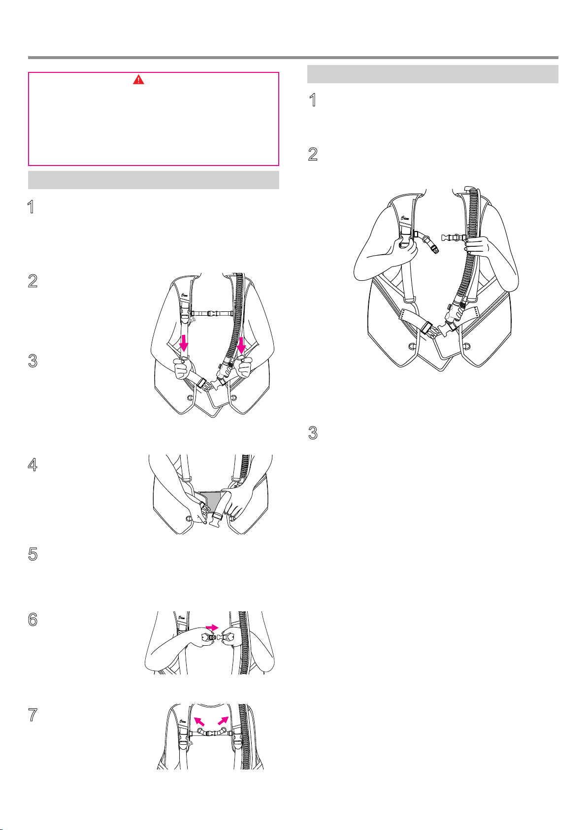
Hold one of the shoulder belts firmly by the hand of the
same side. Release the buckle of the other side of
shoulder belt by the other hand.
2
Release a buckle of chest belt and waist buckle, and
also tear off the Velcro tape of a cummerbelt.
1
Carry a B. C. on the Back
Take Off a B. C.
Warning
●Please wear B. C. in the place where is no body except your
buddy who helps you to wear it. Tanks hit each other and it
becomes the accident.
●Wear B. C. in the state that the shoulder buckles on both
shoulder are fastened. Wearing it while the buckles are
released, the whole tank and B. C. may be dropped and
dangerous.
Slip into the B. C.
jacket and carry it on
the back.
2
Pull down the D-rings
of shoulder belts at
both sides
simultaneously, and fit
to your body.
3
Slightly lengthen a belt in the state that the shoulder
buckles on both right and left shoulders are fastened.
Release a buckle of a waist belt, tear off the Velcro tape
of a cummerbelt, and also loosen the belt. Moreover,
move the hoses to the tank side so that they may not
twist together.
1
Stick the Velcro tapes
of a cummerbelt
together and fasten
the waist buckle.
4
Pull down the end of waist belts at both sides
simultaneously, and fit to your body.
5
6When you insert male
side of a buckle into
the female side, it will
fit in with a sound of
“click”.
7Eliminate the slack of
the belt.
Swing a tank around to the front of you while holding the
shoulder belt by one hand, and place the tank on the ground
by keeping it with the other hand.
3

11
BASIC USAGE
Exhaust Air of a B.C.
Supply Air to a B.C.
When you push “IN” button, air is supplied to a B.C.
□
Supply air by “IN” button. (Underwater and surface)
□Supply air by “ORAL” button. (Surface only)
In the state of keeping enough buoyancy by a fin kick, hold a mouth piece of an inflator in your mouth firmly, push oral button
only while blowing a breath, and supply air into a float.
[ Note ]
●If you continue to supply air to a B. C. which is already full of air, in order to prevent the burst of float, it has structure which
releases air from a relief valve.
Warning
●Do not perform air supply by pushing “ORAL” button underwater. You drink water by mistake, and it may cause an accident
resulting in injury or death.
●Air supply by the “IN” button of an inflator is performed only when air is in a tank. Air is not supplied when there is not
enough air.
□Exhaust air by “ORAL” button.
□Exhaust by exhaust knob.
Take a posture so that the position
of the housing of the left shoulder
becomes the most top of a float
(vertical posture), and then push the
“ORAL” button while facing a inflator
toward surface, air will be exhausted
from a mouth piece portion of
inflator.
Take a posture so that the
position of the relief valve of
the right shoulder becomes the
most top of a float (vertical
posture), and then pull the
exhaust knob, air will be
exhausted from the relief valve
of the right shoulder.
Relief valve.
■In the case of a shoulder relief valve.
Take a posture so that the position of the relief valve of the
right waist becomes the most top of a float (When head first
etc.), and then pull the exhaust knob, air will be exhausted
from the relief valve of the right waist.
■In the case of an under relief valve.
□Exhaust air by pull dump.
Take a posture so that the position
of the housing of the left shoulder
becomes the most top of a float
(vertical posture), and then pull the
remote-control portion, air will be
exhausted from the housing of the
left shoulder.
Take a posture so that the
position of the housing of the left
shoulder becomes the most top
of a float (vertical posture), and
then push the “OUT” button at
hand, air will be exhausted from
the housing.
□Exhaust air by “OUT” button.
[ Note ]
●Exhaust by the “OUT” button is performed only when an
low pressure hose of B. C. is set up correctly and tank valve
is opened.
Housing.
Warning
●When an inflator is not set up correctly such as, B. C. hose
is not installed correctly, tank valve is closed, air
pressure in a tank is not enough, exhaust by the “OUT”
button cannot be performed.
[ Note ]
●Exhaust by pulling the inflator downward is possible even
when the regulator is not attached to the tank.
Warning
●When exhausting with the inflator pulled downward (pull
dump deflation), if it is pulled too hard, it may cause
damage and malfunction, and exhaust may not be possible.
Housing.
■Common
□JA3610 combination valve)
□JA3620 standard valve)
12
2
3
1
Strage Pocket
Adjust Stretch cord
Caution
The storage pocket is not a closed structure.
Before using the product, take measures such as attaching a string
to items so that it will not fall.
Adjust the length of the stretch cord with the cord stopper according to
the stored items.
[ Note ]
Raise the pocket several times to even out the looseness.
Stretch code
Code stopper
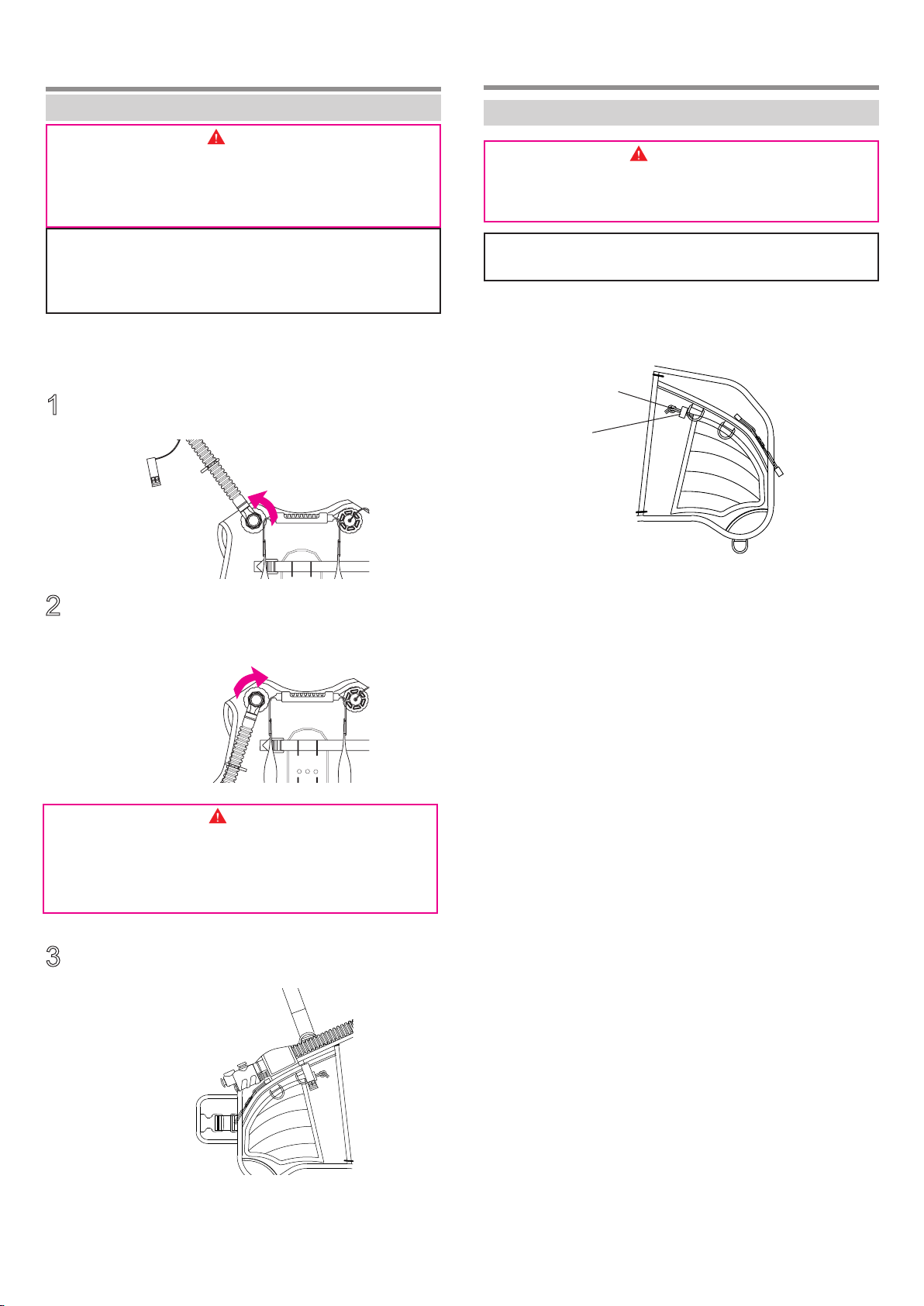
Turn an Inflator from the Back Side.
2 WAY INFLATOR
Warning
●When you turn an inflator from a back side and use it,
please do not fix a corrugated hose to the back side of
the float. Air supply by the “ORAL” button becomes
difficult, and it may cause an accident resulting in injury
or death.
Loosen the thread portion of a housing and remove the
combination valve.
Place the combination valve upside down, adjust the
angle of a convex and a concave portion which is 12
square shapes of a housing, and screw in.
Attach the corrugated hose of the combination valve to B-POSITION.
[ Note ]
●By turning and wearing an inflator from the back side,
simple appearance without a corrugated hose in the left
breast can be rranged.
Warning
●Please adjust correctly the convex and concave portion of
12 angles of a housing, and screw in all the way.
If 12 angles have shifted, it causes an air leakage.
If screwing is insufficient, a housing comes off, and it
may cause an accident resulting in injury or death.
13
Tear off the Velcro tape of the tank head belt.
6
Remove the regulator first stage from the tank.
2
3
Loosen the tank belt, and remove the B. C. from upside
of the tank.
7
Close a tank valve, release the residual pressure inside
of a hose by pushing the purge button of regulator
second stage, and then disconnect the B. C. hose from
a nose. (Refer to page 7)
1
When you move the base of the tank buckle toward the
direction of arrow, belt will be loosened.
5
Tear off the end of tank belt from a Velcro tape, and turn
the buckle.
Draw a belt through the slot of the tank buckle.
4
Warning
●When you remove a B. C. from a tank, please put the tank on the
stable place, such as the flat ground. It is dangerous if it falls.
[ Note ]
●Keep it in the state that a belt is not drawn from a tank
buckle even after removing from B. C., it will make you
easy for next setting.
Tank Buckle
How to Remove a B. C. from a Tank
REMOVE B.C. FROM TANK
Wash Outside
After soaking the whole equipment to fresh water for
about 15 minutes, rinse the whole in water to wash the
salt away.
1
Wash Inside a Float
While pushing “ORAL” button of
inflator, press a faucet of water
service against a mouthpiece
portion, and put fresh water in
float about 1/4.
1
WASH & DRY
Wash away each valve and inflator portion with fresh
water well.
2
Open a tank valve, push “OUT”
button 4-5 times. Water inside a
valve will be drained from the
base of the “OUT” button.
Install regulator first stage to a tank, and connect the
B. C. hose to an inflator.
Hold B. C. so that the housing
position of the base of an inflator
hose may become the bottom, and
also make an inflator position to
the bottom, and drain the water
inside of the float with air by
pushing the “ORAL” button.
4
After blowing air from the mouthpiece of an inflator to
inflate B. C., shake the B. C. fully, and rinse the inside of
float.
2
3
Wash Inside of a Valve. (JA3610)
Repeat the above 1-3 process for
2 to 3 times.
2
1
Caution
●Please do not push water out of the relief valve by using
the pressure while putting air into B. C. It causes the
damage.
Caution
●Equipment may be damaged if soaked in hot water of 50℃
or more.
●Please wash B. C. with fresh water immediately after use.
If the salt attached dries and crystallizes, it causes an
operation failure of a valve.
Dry
Inflate a B. C. by putting air in it about 80% through
inflator mouthpiece.
1
Avoid direct rays, and dry the B. C. completely in the
shade of dry and in good ventilation.
2

14
Periodic Inspection
Warning
●Regardless of frequency and the number of times in use,
please ask your original dealer or authorized distributor
of our company for a periodic inspection per once in a
year.
●Regardless whether or not you use it, a B. C. may not
function normally when you ignore a periodic inspection.
[ Note ]
●Some parts carry out natural deterioration. Exchange of
such parts is also performed by periodic check.
■Wash and dry the B. C. completely.
■Hang it on the hanger and keep it in the place with the dry,
cool and sufficient ventilation where does not get sunshine.
Way of Storage
■Please ask your original dealer or authorized distributor
of our company for a periodic inspection per once in a
year. (Pay Service)
Caution
●Please keep the B. C. hose in
a natural form. Over bending may
cause a kinking and remarkably
short service life.
●Please keep BC without folding. It
shortens the service life of the float
remarkably and causes the air
leakage.
STORAGE & PERIODIC INSPECTION
Service after the Sales
□When your B. C. is out of condition, check it first.
Please refer to the clause of "Troubleshooting" and check
whether it is failure.
□When it is still out of order;
Please contact your original dealer or authorized distributor
of our company.
□ Reserving period of parts.
Our company reserves the performance parts (the parts
required to maintain the function of the product) to repair B.
C. for at least 8 years after the production is discontinued.
Since repair may be possible depending on a problem even
after this reserving period passes, please consult with your
original dealer or authorized distributor of our company.
15
Trouble
TROUBLE SHOOTING
Major Cause Measure
Page
BC does not inflate even if I
push the "IN" button. (Air is
not supplied)
○B.C.hose is not connected correctly.
○Tank valve is not open.
○Air in a tank is not enough.
○You might push exhaust button at
the same time.
○Relief valve is open.
○Connect the B. C. hose correctly.
○Open the tank valve.
○Change to the tank with full of air.
○Do not push exhaust button.
○Do not pull exhaust knob.
7
-
-
11
-
-
B.C. is abnormally heavy. ○Water is in side of a float. ○Drain the water in the float.
-
-
It does not fit when wear it. ○Length of cummerbelt at waist
portion is not adequate.
○Length of shoulder belt is not
sufficient.
○Adjust the cummerbelt.
○Adjust the shoulder belt.
6
9
B. C. cannot be fixed to a
tank firmly
○The way of pass a belt through a
buckle is wrong.
○Pass the belt through tank buckle
correctly, and fix it.
6
BC does not inflate even if I
perform the "Oral Inflation".
(Air is not supplied)
○You might push “OUT” button at the
same time.
○Relief valve is open.
○The ”ORAL” button is pushed at the
time except blowing air.
○Operate “ORAL” button only.
○Do not pull exhaust knob.
○Push “ORAL” button only at the time
blowing air. (Refer to the course of a
diving school)
-
11
8
Exhaust cannot be performed
by “ORAL” button
○Posture is not appropriate. ○Perform button operation while taking a
posture so that the position of the housing
becomes higher than the float portion.
(Refer to the course of a diving school)
13
-
BC does not exhaust even if
I push “out” button.
○B. C. hose is not connected
correctly.
○Tank valve is not open.
○Air in a tank is not enough
○Posture is not appropriate.
○Connect the B. C. hose correctly.
○Open the tank valve.
○Change to the tank with full of air.
○Take a posture so that the position of the
housing of the left shoulder becomes the
most top of a float.
BC does not exhaust even if
I pull the exhaust knob.
○Posture is not appropriate. ○Perform the operation while taking a
posture so that the position of the housing
of the relief valve becomes the most top
of a float.
Air leaks from a relief valve. ○The pressure inside float exceeds a
fixed level.
○A foreign object is stuck in the relief
valve.
○In order to prevent the burst of B. C.
jacket, when inner pressure goes too
high, it has structure which releases air.
○Wash the valve with water well.
13
Air leaks from a mouth piece
portion of an inflator.
○A foreign object is stuck in an oral
valve.
○Wash the inside of inflator with water
well.
Air leaks from a housing at the
shoulder portion of inflator.
○A foreign object is stuck in an
exhaust valve.
○Wash the housing portion with water
well.
B.C. hose cannot be
connected to an inflator.
○Inside of the B.C. hose is
pressurized.
○Thread size of hose coupling is not
adequate as the B.C. hose is not
Bism product.
○Close the tank valve, release the air
pressure in the hose by pushing the
purge button of a regulator
○Use the B. C. hose of attachment.
Buoyancy is insufficient. ○Weight is too heavy. ○Adjust to a reasonable weight.
11
11
8
-
-
-

Memo
16
20200522MJE
Bism CORPORATION
5F, 3-6-18, Higashinihonbashi, Chuo-ku, Tokyo 103-0004
Japan
Phone: +81-3-5640-8126 Fax: +81-3-5640-8131
This manual suits for next models
2
Table of contents
Other Bism Diving Instrument manuals


