Bison NVH-150-T User manual
NVH-240-T ...harvesting better implements!
O P E R A T O R ’ S
M A N U A L
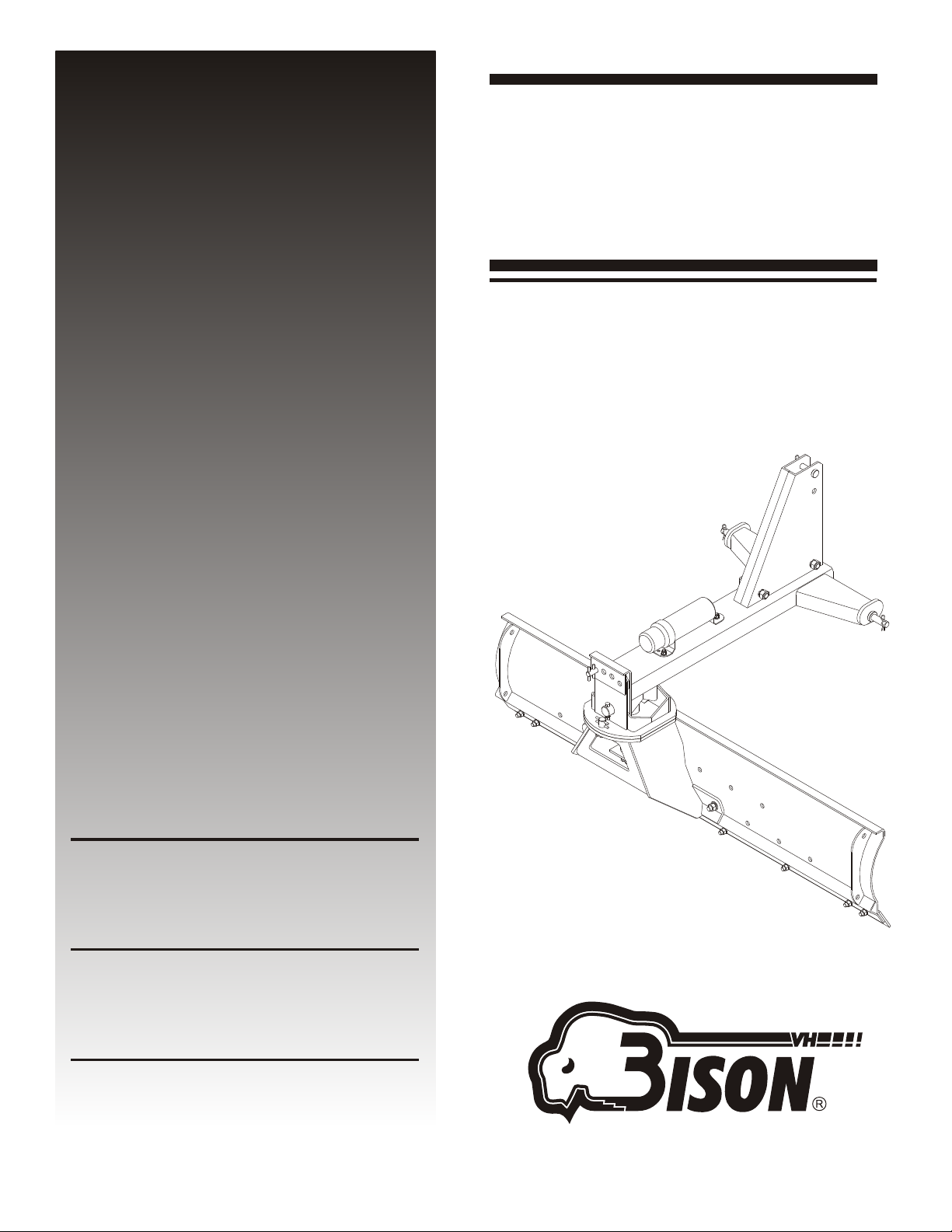
REAR
BLADES
REAR
BLADES
4350-2113-00 (Rev. 09/06/04)
NVH-210-T
NVH-180-T
NVH-150-T
This Safety-alert Symbol indicates a hazard and means
ATTENTION! BECOME ALERT! YOUR SAFETY IS INVOLVED!
Indicates an imminently hazardous situation that, if not avoided, will
result in death or serious injury.
Indicates a potentially hazardous situation that, if not avoided,
could result in death or serious injury, and includes hazards that are
exposed when guards are removed.
Indicates a potentially hazardous situation that, if not avoided, may
result in minor or moderate injury.
Indicates that failure to observe can cause damage to equipment.
Indicates helpful information.
IMPORTANT
NOTE
DANGER
WARNING
CAUTION
TO THE DEALER:
VH
Assembly and proper installation of this product is the responsibility of the BISON dealer. Read manual instructions
and safety rules. Make sure all items on the Dealer's Pre-delivery and Delivery Check Lists in the Operator's Manual
are completed before releasing equipment to the owner.
VH
The dealer must complete the Warranty Registration, located on the BISON website. Warranty claims will be denied
if the Warranty Registration has not been completed.
TO THE OWNER:
VH
Read this manual before operating your BISON equipment. The information presented will prepare you to do a better
and safer job. Keep this manual handy for ready reference. Require all operators to read this manual carefully and
become acquainted with all the adjustment and operating procedures before attempting to operate. Replacement
manuals can be obtained from your selling dealer.
The equipment you have purchased has been carefully engineered and manufactured to provide dependable and
satisfactory use. Like all mechanical products, it will require cleaning and upkeep. Lubricate the unit as specified.
Observe all safety information in this manual and safety decals on the equipment.
VH VH
For service, your authorized BISON dealer has trained mechanics, genuine BISON service parts, and the necessary
tools and equipment to handle all your needs.
VH
Use only genuine BISON service parts. Substitute parts will void the warranty and may not meet standards required for
safe and satisfactory operation. Record the model number and serial number of your equipment in the spaces
provided:
Model: Date of Purchase:
Serial Number: (see Safety & Instructional Decals section for location)
Provide this information to your dealer to obtain correct repair parts.
Throughout this manual, the term IMPORTANT is used to indicate that failure to observe can cause damage to
equipment. The terms CAUTION, WARNING, and DANGER are used in conjunction with the Safety-alert Symbol, (a
triangle with an exclamation mark), to indicate the degree of hazard for items of personal safety.
ii
Introduction
4350-2113-00 (Rev. 09/06/04)

GENERAL INFORMATION
The purpose of this manual is to assist you in oper-
ating and maintaining your rear blade. Read it
carefully. It furnishes information and instructions
that will help you achieve years of dependable per-
formance. These instructions have been compiled
from extensive field experience and engineering
data. Some information may be general in nature,
due to unknown and varying operating conditions.
However, through experience and these instruc-
tions, you should be able to develop procedures
The illustrations and data used in this manual were
current at the time of printing. However, due to pos-
sible inline production changes, your machine may
vary slightly in detail. We reserve the right to rede-
sign and change the machines as may be neces-
Throughout this manual, references are made to
right and left direction. These are determined by
standing behind the tractor facing the direction of
forward travel.
sary without notification.
suitable to your particular situation.
TABLE OF CONTENTS
INTRODUCTION
GENERAL INFORMATION
SPECIFICATIONS
SAFETY RULES
SAFETY & INSTRUCTIONAL DECALS
OPERATION
OWNER SERVICE
ASSEMBLY
PARTS INDEX
BOLT TORQUE CHART
BOLT SIZE CHART & ABBREVIATIONS
WARRANTY
ii
1
2
3
5
7
13
15
26
31
32
33
1
General Information
4350-2113-00 (Rev. 09/06/04)

NVH-150-T / NVH-180-T / NVH-210-T / NVH-240-T
SPECIFICATIONS
NVH-150-T
Manually
adjusted angle,
tilt and offset
Cat. 1
iMatch Compatible
Formed steel
channel frame
½" x 6" reversible
360 Degrees
3, up to 53
degrees each
side
3, up to 53
degrees each
side
1/4"
60"
17"
Progressive-formed
Full bend
6" or 12" left or right
65HP (2WD)
60HP (4WD)
3, up to 22
degrees up
and down
392 lbs.
*Tecnomec Agricola, S.A. de C.V. reserves the right to make any changes deemed necessary to
the specifications without prior notice.
NVH-180-T
Manually
adjusted angle,
tilt and offset
Cat. 1
iMatch Compatible
Formed steel
channel frame
½" x 6" reversible
360 Degrees
3, up to 53
degrees each
side
3, up to 53
degrees each
side
1/4"
72"
17"
Progressive-formed
Full bend
6" or 12" left or right
65HP (2WD)
60HP (4WD)
3, up to 22
degrees up
and down
422 lbs.
NVH-210-T
Manually
adjusted angle,
tilt and offset
Cat. 1
iMatch Compatible
Formed steel
channel frame
½" x 6" reversible
360 Degrees
3, up to 53
degrees each
side
3, up to 53
degrees each
side
1/4"
84"
17"
Progressive-formed
Full bend
6" or 12" left or right
65HP (2WD)
60HP (4WD)
3, up to 22
degrees up
and down
448 lbs.
Models
Features & Specifications
Angle, tilt, & offset
Hitch compatibility
Frame
Cutting edge
Angle/Pivot
Angle-Forward
Angle-Reverse
Moldboard thickness
Moldboard length
Moldboard height
Moldboard type
Moldboard upper edge
Offset (or swing)
Tractor max. HP
Tilt
Operating weight
NVH-240-T
Manually
adjusted angle,
tilt and offset
Cat. 1
iMatch Compatible
Formed steel
channel frame
½" x 6" reversible
360 Degrees
3, up to 53
degrees each
side
3, up to 53
degrees each
side
1/4"
96"
17"
Progressive-formed
Full bend
6" or 12" left or right
65HP (2WD)
60HP (4WD)
3, up to 22
degrees up
and down
476 lbs.
1
General Information
4350-2113-00 (Rev. 09/06/04)

TRAINING
Safety instructions are important! Read all
attachment and power unit manuals; follow all
safety rules and safety decal information.
(Replacement manuals are available from your
dealer). Failure to follow instructions or safety
rules can result in serious injury or death.
If you do not understand any part of this manual
and need assistance, see your dealer.
Know your controls and how to stop engine and
attachment quickly in an emergency.
Operators must be instructed in and be capable
of the safe operation of the equipment, its
attachments, and all controls. Do not allow anyone
to operate this equipment without proper
instructions.
Never allow children or untrained persons to
operate equipment.
PREPARATION
Check that all hardware is properly installed.
Always tighten to torque chart specifications
unless instructed otherwise in this manual.
Always wear relatively tight and belted clothing
to avoid entanglement in moving parts. Wear
sturdy, rough-soled work shoes and protective
equipment for eyes, hair, hands, hearing, and head.
Make sure attachment is properly secured,
adjusted, and in good operating condition.
Power unit must be equipped with ROPS or
ROPS cab and seat belt. Keep seat belt securely
fastened. Falling off power unit can result in death
from being run over or crushed. Keep foldable
ROPS systems in “locked up” position at all times.
Make sure all safety decals are installed.
Replace if damaged. (See Safety & Instructional
Decals section for location).
A minimum 20% of tractor and equipment
weight must be on the tractor front wheels when
attachments are in transport position. Without this
weight, tractor could tip over, causing personal
injury or death. The weight may be attained with a
loader, front wheel weights, ballast in tires or front
tractor weights. Weigh the tractor and equipment.
Do not estimate.
OPERATION
Do not allow bystanders in the area when
operating, attaching, removing, assembling, or
servicing equipment.
Do not operate equipment while under the
influence of alcohol or drugs.
Operate only in daylight or good artificial light.
Keep hands, feet, hair, and clothing away from
equipment while engine is running. Stay clear of all
moving parts.
(Safety Rules continued on next page)
SAFETY RULES
ATTENTION! BECOME ALERT! YOUR SAFETY IS INVOLVED!
Safety is a primary concern in the design and
manufacture of our products. Unfortunately, our
efforts to provide safe equipment can be wiped
out by an operator’s single careless act.
In addition to the design and configuration of
equipment, hazard control and accident prevention
are dependent upon the awareness, concern,
judgement, and proper training of personnel
involved in the operation, transport, maintenance,
and storage of equipment.
It has been said “The best safety device is an
informed, careful operator.” We ask you to be that
kind of operator.
2
Specifications
4350-2113-00 (Rev. 09/06/04)
This manual suits for next models
3
Table of contents
Other Bison Farm Equipment manuals

Popular Farm Equipment manuals by other brands

Schaffert
Schaffert Rebounder Mounting instructions

Stocks AG
Stocks AG Fan Jet Pro Plus 65 Original Operating Manual and parts list

Cumberland
Cumberland Integra Feed-Link Installation and operation manual

BROWN
BROWN BDHP-1250 Owner's/operator's manual

Molon
Molon BCS operating instructions

Vaderstad
Vaderstad Rapid Series instructions


