GE Jenbacher JGS 320 GS-L.L Quick start guide

ELECTRIC WIRING DIAGRAM
J N795
Nelson Gardens LFG
4 x JGS 320 GS-L.L

Modific.
a
0
Date Name
Date
Desig.
Print
Check
1
18.01.06
Senfter M.
24.04.12
Pieschnik A.
4 x JGS 320 GS-L.L
Nelson Gardens LFG
DIR: J:\EPLAN4\P\ANLAGEN\NXXX\N7XX\JN795.P
2 3
KW 05 - 2011
4
Cover sheet Electric wiring diagram
5 6 7
SO-Nr.
Project
Suffix
Wiring
diagram
8662
J xxxx
J N795
8
+U /
9
1
2
This drawing is confidential and proprietary to the General Electric Company.
It may not be used in any form, or reproduced in any manner,
without the express written permission of the General Electric Company.
Copyright, General Electric Company, 2011
USA
Nelson Gardens LFG
4 x JGS 320 GS-L.L
J N795
The wiring diagram includes : 194 Sheets

Modific.
1
a
0
Date Name
Date
Desig.
Print
Check
1
18.01.06
Senfter M.
24.04.12
Pieschnik A.
4 x JGS 320 GS-L.L
Nelson Gardens LFG
DIR: J:\EPLAN4\P\ANLAGEN\NXXX\N7XX\JN795.P
2 3
KW 05 - 2011
4
Electric wiring diagram Version
5 6 7
SO-Nr.
Project
Suffix
Wiring
diagram
8662
J xxxx
J N795
8
+U /
9
2
3
a
Version
23.03.2012
Date:
20.02.2012
05.04.2012
Mader Manfred
Release: Name
Mader Manfred
Senfter M.
+A1
Modifications: (Groups)
+U created
+B.+G,+M+A,+DF
during manufacturing
Comment:
Preliminary documentation
before manufacturing

Modific.
2
0
Date Name
Date
Desig.
Print
Check
1
18.01.06
Senfter M.
24.04.12
Pieschnik A.
4 x JGS 320 GS-L.L
Nelson Gardens LFG
DIR: J:\EPLAN4\P\ANLAGEN\NXXX\N7XX\JN795.P
2 3
KW 05 - 2011
4
Over view
5 6 7
SO-Nr.
Project
Suffix
Wiring
diagram
8662
J xxxx
J N795
8
+U /
9
3
4
Over view
Parameters for the operation
of GE Jenbacher Engines
acc. TI.Nr.: 1100-0110
Modifications of Design
reserved.
Protection against electric shocks hazard
earthing, equipotential bonding, has to be
provided by the Customer at installation
according to local Standards !
At staes of delivery the engine
is prepared for the protection by
automatic disconnection of supply
in TN-Systems according to
HD 60364-4-41 / IEC 60364-4-41.
This Wiring Diagram is designed with
a CAE-System.
Modifications will be occupied by
GE Jenbacher
No.
The Numbers in the circles are in
Relation with the Numbers in the
Interface-List J
All Cables between the
Switchboards and the Engine
have to be in flexible mode.
N795
Modific.
3
0
Date Name
Date
Desig.
Print
Check
1
18.01.06
Senfter M.
24.04.12
Pieschnik A.
4 x JGS 320 GS-L.L
Nelson Gardens LFG
DIR: J:\EPLAN4\P\ANLAGEN\NXXX\N7XX\JN795.P
2 3
KW 05 - 2011
4
Diagram index
5 6 7
SO-Nr.
Project
Suffix
Wiring
diagram
8662
J xxxx
J N795
8
+U /
9
4
5
Diagram index
Page Denomination Modifications Page Denomination Modifications
+U/1
+U/2
+U/3
+U/4
+U/5
+U/6
+U/7
+U/8
+U/9
+U/10
+U/11
+U/12
+U/13
+U/14
+U/15
Cover sheet Electric wiring diagram
Electric wiring diagram Version
Over view
Diagram index
E-Diagram
Over view groups
Over view groups
Protection: Generator
Grid Import/Export Controller
Gangway
Over view Panels
Electrical connections
Potential equalization
Bus diagram
Bus diagram
a
a
+U/16
+U/17
+U/18
+U/19
+U/20
+U/21
+U/22
+U/23
+U/24
+U/25
+U/26
+U/27
MODBUS-RTU
Over view Software
Legend of Symbols
Legend of Symbols
Requirements for Cablings NEC
Cable with DIANE
Over view cables
Kabelcbersicht
Kabelcbersicht
Kabelcbersicht
Kabelcbersicht
Kabelcbersicht

Modific.
4
0
Date Name
Date
Desig.
Print
Check
1
18.01.06
Senfter M.
24.04.12
Pieschnik A.
4 x JGS 320 GS-L.L
Nelson Gardens LFG
DIR: J:\EPLAN4\P\ANLAGEN\NXXX\N7XX\JN795.P
2 3 4
E-Diagram
5 6 7
SO-Nr.
Project
Suffix
Wiring
diagram
8662
J L603
J N795
8
+U /
9
5
6
Delivery
GE Jenbacher
Delivery
from Customer
Delivery
from Customer
Auxiliaries
..A
3
Over voltage protection
..A
12
Cu Busbar
Cu Busbar
76
81
84.1
U
<
24VDC
78
82
79
83
24VDC
....kV
480/277V
...kVA
80
84
-MT1
Phase MTM ..x250mmý
I(N)
I >
I >>
2,5xI(N)
M
+L..-Q..
PE,N MTM .x...mmý
Phase MTM .x...mmý
G
3
3
2000/5A
10P10,15VA
3
2000/5A
1FS5,15VA
mains
1
3A
3A
Engine frame
480V/ 3/120V/ 3
15VA, Cl.1
480V/ 3/120V/ 3
15VA, Cl.1
Dif protection
10
+A1-4
75
85
13
UKUf
Mains monitoring
device
2A
Synchronisation
Measurement and
Synchronisation
2A
Measurement
1311kVA 1577A cos =0,8
1059kW 1274A cos =1
f>: 61,5 Hz
f<: 59 Hz
U<: 90 % UN
U>: 110 % UN
KU: 8 Grad
Indicators
AA
cosHz
AVe
V
kVA kVarkW
kvarh
kWh
Generator 1-4
480/277V ñ5% 60Hz

Modific.
5
0
Date Name
Date
Desig.
Print
Check
1
18.01.06
Senfter M.
24.04.12
Pieschnik A.
4 x JGS 320 GS-L.L
Nelson Gardens LFG
DIR: J:\EPLAN4\P\ANLAGEN\NXXX\N7XX\JN795.P
2 3
KW 40 - 2011
4
Over view groups
5 6 7
SO-Nr.
Project
Suffix
Wiring
diagram
8662
J xxxx
J N795
8
+U /
9
6
7
Over view groups
+U
+B
+G1
+M1
+A1
+DF1
+G2
+M2
+A2
Over view
Part reference list
Generator 1
Module interface cubicle 1
Module control panel 1
HERMES
Generator 2
Module interface cubicle 2
Module control panel 2
Location
+E1
+P1
+E2
+P2
Gas engine 1
Periphery 1
Gas engine 2
Periphery 2

Modific.
6
0
Date Name
Date
Desig.
Print
Check
1
18.01.06
Senfter M.
24.04.12
Pieschnik A.
4 x JGS 320 GS-L.L
Nelson Gardens LFG
DIR: J:\EPLAN4\P\ANLAGEN\NXXX\N7XX\JN795.P
2 3
KW 40 - 2011
4
Over view groups
5 6 7
SO-Nr.
Project
Suffix
Wiring
diagram
8662
J xxxx
J N795
8
+U /
9
7
8
Over view groups
+G3
+M3
+A3
+G4
+M4
+A4
Generator 3
Module interface cubicle 3
Module control panel 3
Generator 4
Module interface cubicle 4
Module control panel 4
Location
+E3
+P3
+E4
+P4
Gas engine 3
Periphery 3
Gas engine 4
Periphery 4

Modific.
7
0
Date Name
Date
Desig.
Print
Check
1
18.01.06
Senfter M.
24.04.12
Pieschnik A.
4 x JGS 320 GS-L.L
Nelson Gardens LFG
DIR: J:\EPLAN4\P\ANLAGEN\NXXX\N7XX\JN795.P
2 3
KW 05 - 2011
4
Protection: Generator
5 6 7
SO-Nr.
Project
Suffix
Wiring
diagram
8662
J xxxx
J N795
8
+U /
9
8
9
11
27
59
50/51
64/59N
46
40
81 >
81 <
Multi measuring and monitoring device
Under voltage
Over voltage
Overload/Short circuit
Unbalance - Voltage
Unbalance - Current
Failure Excitation
Over frequency
Under frequency
49
53
32
37
P>
38
DIANE
Windings temperature
Excitation voltage low
Reverse power
Power <
Power >
Bearing temperature
Protection: Generator
27/59
81 <>
78
Relay
Voltage < >
Frequency < >
KU
24
56
Voltage/Frequency Function
Excitation >
Generator internal

Modific.
8
0
Date Name
Date
Desig.
Print
Check
1
18.01.06
Senfter M.
24.04.12
Pieschnik A.
4 x JGS 320 GS-L.L
Nelson Gardens LFG
DIR: J:\EPLAN4\P\ANLAGEN\NXXX\N7XX\JN795.P
2 3
KW 40 - 2011
4
Grid Import/Export Controller
5 6 7
SO-Nr.
Project
Suffix
Wiring
diagram
8662
J xxxx
J N795
8
+U /
9
9
10
GRID CB
Busbar
480V/120V
GRID
3 x .../5A
4-20mA = -10.000KW - 0 - + 10.000KW
power
transducer
(both directions)
mA
X
CUSTOMER
Controller
0-20mA = 50-100%Pn
W= xxKW
set point
GE Jenbacher
Y
Engine 1
DI.ANE Power Controller
Engine 2
DI.ANE Power Controller
Engine 3
DI.ANE Power Controller
Engine 4
DI.ANE Power Controller

Modific.
9
0
Date Name
Date
Desig.
Print
Check
1
18.01.06
Senfter M.
24.04.12
Pieschnik A.
4 x JGS 320 GS-L.L
Nelson Gardens LFG
DIR: J:\EPLAN4\P\ANLAGEN\NXXX\N7XX\JN795.P
2 3
KW 05 - 2011
4
Gangway
5 6 7
SO-Nr.
Project
Suffix
Wiring
diagram
8662
J xxxx
J N795
8
+U /
9
10
11
Evacuation route direction
500mm
according : IEC 60364-7-729
600mm

Modific.
10
0
Date Name
Date
Desig.
Print
Check
1
18.01.06
Senfter M.
24.04.12
Pieschnik A.
4 x JGS 320 GS-L.L
Nelson Gardens LFG
DIR: J:\EPLAN4\P\ANLAGEN\NXXX\N7XX\JN795.P
2 3
KW 05 - 2011
4
Over view Panels
5 6 7
SO-Nr.
Project
Suffix
Wiring
diagram
8662
J xxxx
J N795
8
+U /
9
11
12
6002000200
Side wall
(HxBxT) 2000x1000x600
1000
+Ax
Side wall

Modific.
11
0
Date Name
Date
Desig.
Print
Check
1
18.01.06
Senfter M.
24.04.12
Pieschnik A.
4 x JGS 320 GS-L.L
Nelson Gardens LFG
DIR: J:\EPLAN4\P\ANLAGEN\NXXX\N7XX\JN795.P
2 3 4
Electrical connections
5 6 7
SO-Nr.
Project
Suffix
Wiring
diagram
8662
J K620
J N795
8
+U /
9
12
13
Cables for
Auxiliaries
at the customer side
+MC1
Auxiliaries Cubicle
Gas train
Engine
+ -
Batteries
+-
Battery Cables
Control Cables to Gas train
Aux. Connection
Junction Box
+E-XHK
control cables MCC
Module interface cubicle
+M1
Generator
Canbus Cable
Ethernet Cable
Control Cable
24VDC Supply
Generator cables
CT Cables, measuring CT's
+L1
Generator Switchgear
at the customer side
CT Cables, protection CT's
Cables for CB controll
and measurement
Peripheral
Level Switches
Alarms...
Control Cables
+A1
Module Control Panel
Schematic drawing:
for exact position of
equipment and cable outlet
look at module drawing
Control Cables
Control at
the Customer

Modific.
12
0
Date Name
Date
Desig.
Print
Check
1
18.01.06
Senfter M.
24.04.12
Pieschnik A.
4 x JGS 320 GS-L.L
Nelson Gardens LFG
DIR: J:\EPLAN4\P\ANLAGEN\NXXX\N7XX\JN795.P
2 3
KW 05 - 2011
4
Potential equalization
5 6 7
SO-Nr.
Project
Suffix
Wiring
diagram
8662
J xxxx
J N795
8
+U /
9
13
14
*
Cross-sectional area according to IEC 60364-5-54 and national standards.
Querschnitt nach IEC 60364-5-54 und nationalen Normen.
Secci¢n conforme IEC 60364-5-54 e normas nacional.
Section conforme IEC 60364-5-54 et normes nationales.
Sezione conforme IEC 60364-5-54 e norme nazionale.
Frame
Engine
50mmý 50mmý
G
3 ~
4
16mmý
ò 50mmý
CU
XH
-IFL 4
Equipotential bonding
+ M
3
XH
ò 16mmý
CU
+ A
-IFL 3
Equipotential bonding
25mmý
CU
Gas train
Pipe: -Exhaust gas
Pipe: -water
...
*
Potential compensation bar

Modific.
13
0
Date Name
Date
Desig.
Print
Check
1
18.01.06
Senfter M.
24.04.12
Pieschnik A.
4 x JGS 320 GS-L.L
Nelson Gardens LFG
DIR: J:\EPLAN4\P\ANLAGEN\NXXX\N7XX\JN795.P
2 3
KW 47 - 2010
4
Bus diagram
5 6 7
SO-Nr.
Project
Suffix
Wiring
diagram
8662
J N795
8
+U /
9
14
15
Connection to BMS/PCS
400
+A1
Module control panel
DIANE.XT
X2X
Switch
Monteur
DIANE WIN
Ethernet
Patch
yellow
X2X
CAN
Module interface cubicle
CAN
Ignition
IC
92x

Modific.
14
0
Date Name
Date
Desig.
Print
Check
1
18.01.06
Senfter M.
24.04.12
Pieschnik A.
4 x JGS 320 GS-L.L
Nelson Gardens LFG
DIR: J:\EPLAN4\P\ANLAGEN\NXXX\N7XX\JN795.P
2 3
KW 40 - 2011
4
Bus diagram
5 6 7
SO-Nr.
Project
Suffix
Wiring
diagram
8662
J xxxx
J N795
8
+U /
9
15
16
PC
202
DFš-Central unit
Telephone
connection
204
WWW
INTERNET
Ethernet
Patch
Ethernet
Patch
WAN
LAN1
ETH2
ETH1
Ethernet
Patch
Switch
yellow blue
DIANE.XT
+A1
yellow
FIREWALL
DIANE WIN 1
Monteur
USB
205
LAN2 LAN3
+A1
LAN4
DMZ/WAN2
Ethernet
Patch
Switch
PC
203
DFš-Central unit
DIANE.XT
+A2
yellow
Monteur
Ethernet
Patch
Switch
DIANE.XT
+A3
yellow
Monteur
Ethernet
Patch
Switch
DIANE.XT
+A4
yellow
Monteur

Modific.
15
0
Date Name
Date
Desig.
Print
Check
1
18.01.06
Senfter M.
24.04.12
Pieschnik A.
4 x JGS 320 GS-L.L
Nelson Gardens LFG
DIR: J:\EPLAN4\P\ANLAGEN\NXXX\N7XX\JN795.P
2 3
KW 40 - 2011
4
MODBUS-RTU
5 6 7
SO-Nr.
Project
Suffix
Wiring
diagram
8662
J xxxx
J N795
8
+U /
9
16
17
Limit of delivery: GE Jenbacher
-SSL 400
Busterminal Module control panel
400
Computer: at the customer
MODBUS-RTU Master
PLC
Module control 1
CP = Communications processor
Transmission procedure = MODBUS-RTU-Protocol
CP
Slave 11D
RS 485 Bus cable
PLC
Module control 2
CP
Slave 12D
PLC
Module control 3
CP
Slave 13D
PLC
Module control 4
CP
Slave 10D

Modific.
16
0
Date Name
Date
Desig.
Print
Check
1
18.01.06
Senfter M.
24.04.12
Pieschnik A.
4 x JGS 320 GS-L.L
Nelson Gardens LFG
DIR: J:\EPLAN4\P\ANLAGEN\NXXX\N7XX\JN795.P
2 3
KW 05 - 2011
4
Over view Software
5 6 7
SO-Nr.
Project
Suffix
Wiring
diagram
8662
J xxxx
J N795
8
+U /
9
17
18
Over view Software
File:
N795
Module control
RPS V3.2x
CPU
M01 (0B)
M02 (0C)
M03 (0D)
M04 (0E)
M05 (0F)
M06 (10)
M07 (11)
M08 (12)
M09 (13)
M10 (14)
M11 (15)
M12 (16)
M13 (17)
M14 (18)
M15 (19)
M16 (1A)
S01 (1F)
Overview
Enable
X
X
X
X
X
Overview
X
X
X
X
Name
M01
M02
M03
M04
M05
M06
M07
M08
M09
M10
M11
M12
M13
M14
M15
M16
S01
ALL
DIA.NE WIN:
WINSERVER 1
Application
N795
N795
N795
N795
0000
0000
0000
0000
0000
0000
0000
0000
0000
0000
0000
0000
0000
N795
W_A
W_A
W_A
W_A
W_A
W_A
W_A
W_A
W_A
W_A
W_A
W_A
W_A
W_A
W_A
W_A
W_ST
W_Z

Modific.
17
0
Date Name
Date
Desig.
Print
Check
1
18.01.06
Senfter M.
24.04.12
Pieschnik A.
4 x JGS 320 GS-L.L
Nelson Gardens LFG
DIR: J:\EPLAN4\P\ANLAGEN\NXXX\N7XX\JN795.P
2 3
KW 05 - 2011
4
Legend of Symbols
5 6 7
SO-Nr.
Project
Suffix
Wiring
diagram
8662
J K620
J N795
8
+U /
9
18
19
NO Contact
NC Contact
push button NO
push button NC
camshaft switch
lockable NO
Emergency push button
temperature switch NC
pressure switch NO
pressure switch NC
NO Contact extern
(interface)
NC Contact extern
(interface)
F
P
Emergency push button
extern (interface)
flow switch NC
extern (interface)
pressure switch COC
extern (interface)
temperature switch COC
extern (interface)
miniature circiut breaker
fuse
temperature sensore
thermo couple
temperature sensore
PT100
temperature sensore
PTC
resistor
potentiometer
M
~
3
I
P
K
coil for
relay/ contactor
coil for
coupling relay
electromagnetic
valve
terminal
fuse clip
diode
three-phase motor
battery
measuring transducer
(pressure/current)
pick up
coil

Modific.
18
0
Date Name
Date
Desig.
Print
Check
1
18.01.06
Senfter M.
24.04.12
Pieschnik A.
4 x JGS 320 GS-L.L
Nelson Gardens LFG
DIR: J:\EPLAN4\P\ANLAGEN\NXXX\N7XX\JN795.P
2 3
KW 05 - 2011
4
Legend of Symbols
5 6 7
SO-Nr.
Project
Suffix
Wiring
diagram
8662
J xxxx
J N795
8
+U /
9
19
20
IFL.. = Interface
NO = Normal open contact
NC = Normal closed contact
COC = change over contact
LABELING
XXX
LED
A-meter
volt meter
device
earth
protection earth
ground
shield
feeding extern
(interface)
interface
see Interface List
(see Interface List)
motor
driven
under/over
frequency
Single Line Diagram
1350A
3375A
M
undervoltage
trip coil
f
under/over
voltage
3 phase
U
3
I >
I >>
3
KU
micro
interuption
G
draw out
type
Generator
circuit breaker
voltage transformer
current transformer
transformer
fuse
grid monitoring device
shunt trip
coil
CONVERSION TABLE:
6/0 = 000000
5/0 = 00000
4/0 = 0000
3/0 = 000
2/0 = 00
1/0 = 0
AWG Number
1
2
3
4
5
6
7
8
9
10
11
12
13
14
15
16
17
18
19
20
21
22
23
24
25
26
27
28
29
30
31
32
33
34
35
36
37
38
39
40
dia. inch
0,58
0,517
0,46
0,41
0,365
0,325
0,289
0,258
0,229
0,204
0,182
0,162
0,144
0,128
0,144
0,102
0,0907
0,0808
0,072
0,0641
0,0571
0,0571
0,0453
0,0403
0,0359
0,032
0,0285
0,0253
0,0226
0,0201
0,0179
0,0159
0,0142
0,0126
0,0113
0,01
0,00893
0,00795
0,00708
0,00631
0,00562
0,00500
0,00445
0,00397
0,00353
0,00314
dia. mm
14,73
13,12
11,7
10,4
9,26
8,25
7,35
6,54
5,83
5,19
4,62
4,11
3,66
3,26
2,91
2,59
2,30
2,05
1,83
1,63
1,45
1,45
1,15
1,02
0,912
0,812
0,723
0,644
0,573
0,511
0,455
0,405
0,361
0,321
0,286
0,255
0,227
0,202
0,180
0,160
0,143
0,127
0,113
0,101
0,0897
0,0799
170,30
135,10
107
85
67,4
53,5
42,4
33,6
26,7
21,1
16,8
13,3
10,5
8,36
6,63
5,26
4,17
3,31
2,62
2,08
1,65
1,65
1,04
0,823
0,653
0,518
0,41
0,326
0,258
0,205
0,162
0,129
0,102
0,081
0,0642
0,0509
0,0404
0,0320
0,0254
0,0201
0,0160
0,0127
0,0100
0,00797
0,0063
0,00501
mmý
Table of contents
Other GE Industrial Equipment manuals

GE
GE PWS Manual

GE
GE Mark VIeS Parts list manual

GE
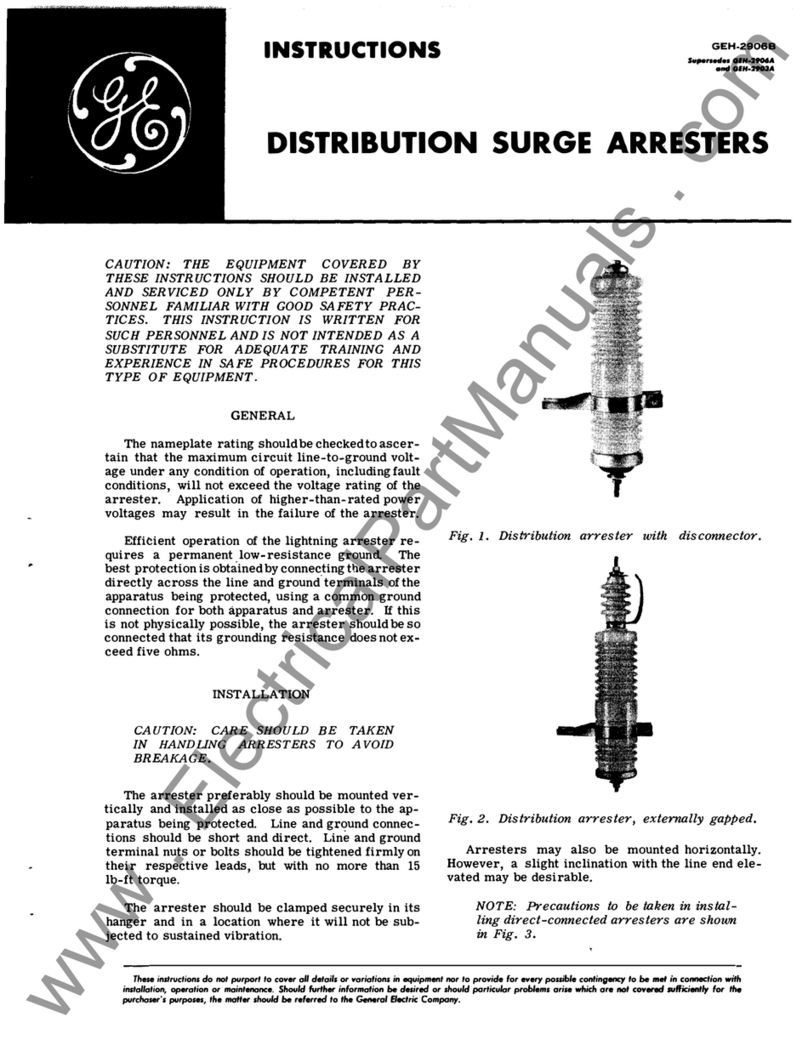
GE GEH-2906B User manual

GE
GE PACSystems* RX3i User manual

GE
GE AKD-20 AR Manual

GE
GE AKD-8 User manual

GE
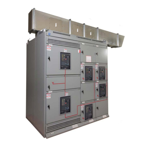
GE MicroVersaTrip Plus User manual

GE
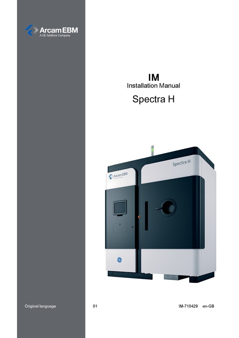
GE ArcamEBM Spectra H User manual

GE
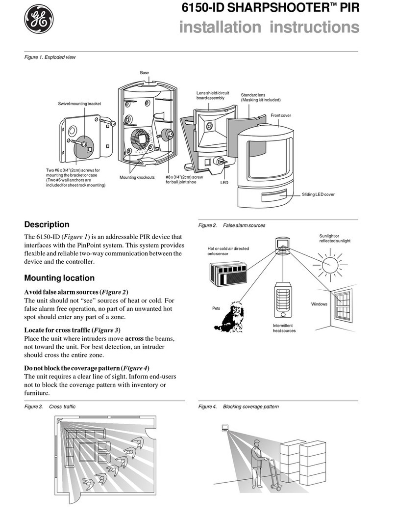
GE SHARPSHOOTER 6150-ID User manual

GE
GE ecomagination Profibus DP AF-650 GP User manual