BITREK BI-868 TREK HW2 User manual

DYSCOVI SYSTEMS RPE LIMITED
Company code 16303375, account №260075014037759
In “UKREXIMBANK” in Kyiv
MFI 380333, tax number 163033726585
www.bitrek.com.ua
+380 44 507 02 07
95-S Vidradniy avenue, Kyiv, Ukraine, 03061. Phone +38044 507 02 07. Fax +38044 507 02 02. www.bitrek.com.ua, sales@bitrek.com.ua
Vehicles Tracking Device
BI-868 TREK HW2
Operating manual
Version 2019.11.1

2
www.bitrek.com.ua
+380 44 507 02 07
Introduction ..........................................................................................3
Safety requirements within installation and maintenance of "BI-868
TREK HW2" tracking device ..............................................................3
Transportation and storage...............................................................3
Warranty........................................................................................3
Device ..................................................................................................4
Purpose..........................................................................................4
Operation principles.........................................................................4
Technical specifications ....................................................................5
Design of tracking device .................................................................6
Supply package...............................................................................6
Preparation for operation, commissioning .................................................6
SIM-card installation........................................................................6
Connector for power supply and peripherals .......................................7
Assembly, commissioning .......................................................................7
Assembly recommendations .............................................................7
Electrical connections.......................................................................8
Device to computer connection .........................................................8
Description of indication elements .....................................................9
Adjustment of "BI-868 TREK HW2" device............................................... 10
Basic information .......................................................................... 10
List of information commands to operate the device .......................... 11
List of control commands to operate the device................................. 13
Basic configuration ........................................................................ 15
Security settings ........................................................................... 16
Adjustment of I/O elements............................................................ 17
Notifications ................................................................................. 21
Roaming options ........................................................................... 21
Appendix 1 - Device parameters ............................................................ 22
Appendix 2 - List of I/O elements........................................................... 29

3
www.bitrek.com.ua
+380 44 507 02 07
Introduction
Safety requirements within installation and maintenance
of "BI-868 TREK HW2" tracking device
Technical staff involved in installation of tracking device is in charge
for compliance with security measures, as well as the staff responsible for
equipment at the work area.
Work area shall be in conformity with the fire safety regulations in
accordance with GOST 12.1.004 and electrical safety in accordance with
GOST 12.1.019.
Vehicles at the work area shall comply with the occupational safety
and health rules in accordance with the DNAOP (State regulations on
labor protection) 0.00-1.28-97.
To prevent damage, device shall be stored in a shock-proof
packaging. Before using, place the device so that you can see the
indication display elements. Before connecting/disconnecting the power
socket and inputs/outputs, turn off the power supply.
Transportation and storage
Transportation of tracking device in the transport packaging of the
manufacturer is allowed by all kinds of enclosed land and sea transport
(rail cars, containers, vehicles of closed type, bilges, etc.). Transportation
in pressurized heated compartments of the aircraft is allowed.
Transportation and storage shall be carried out under conditions in
compliance with storage conditions 3 according to GOST 15150-69.
Transportation and storage shall comply with requirements
specified by the signs on the packages.
Warranty
Warranty period of operation of tracking device "BI-868 TREK HW2"
is 12 months from the date of sale of the device.
The warranty obligations of the manufacturer are valid if the
consumer observes the requirements of this manual. In case of their
violation, or at any mechanical or electrical damages caused by factors
other than specified by this manual, the warranty shall be considered null
and void.

4
www.bitrek.com.ua
+380 44 507 02 07
Device
Purpose
Tracking device "BI-868 TREK HW2" shall be applied to solve issues
of navigation, remote control and monitoring of a vehicle or other remote
object.
The tracking device is designed to be installed on any mobile or
remote stationary object in order to:
determine the geographical coordinates, speed and direction
of movement;
control actuating mechanisms;
transmit data to the control dispatching center.
Data communication channel is the network of mobile
communication operator with GSM standard 900/1800 or GSM
850/900/1800/1900. LBS, GPS or LBS, GPS/GLONASS are used to
determine the coordinates.
Device shall be installed out of reach of the driver. The device is not
designed to run on water transport.
Operation principles
In real time mode the tracking device:
determines location and movement parameters of the object
(time, geographical coordinates, speed, and direction);
collects and processes information from the analog and
discrete sensors;
ensures control over actuating mechanisms upon command
from the control dispatching panel.
Received data are recorded and stored in an internal log, which is
implemented on microchip of nonvolatile memory. At specified intervals
or according to event entries from this log are sent to the server of the
dispatcher via the GSM network. Exchange of information is carried out
by means of GPRS and SMS channels.
Operation of the device in "on-line" mode is possible only at
presence of the network coverage of cellular transmission by GSM
900/1800 standard. Outside GSM network coverage, the tracking unit
operates in the "black box" mode, i.e., it records all information in the
nonvolatile memory and sends it when the vehicle is entering a GSM
coverage area.

5
www.bitrek.com.ua
+380 44 507 02 07
Technical specifications
Table 1 - Technical specifications
No.
Parameters
Characteristics
1
Data transfer standard
GSM 850/900/1800/1900
2
Communication channels
GPRS, SMS
3
GPRS class
10
4
Navigation system
LBS, GPS or LBS,
GPS/GLONASS
5
GPS and GSM antennas
Internal
6
Accelerometer
+
7
SIM-cards
1
8
Digital input with active "1"
1
9
Digital output
1
10
Analogue inputs
2
11
Voltage range of digital input
From 0 V to 40 V
12
Type of digital output
Open collector
13
Maximum load current of discrete output
0,5 A
14
Voltage range of analogue inputs
From 0 V to 27 V
15
Power type
Permanent
16
Internal battery
1000 mAh
17
Power supply
From 9 V to 36 V
18
Average current consumption
(12 V)
60 mA
19
Maximum current consumption
(12 V)
350 mA
20
Volume of non-volatile memory
2 MB (65,000 records)
21
Operating temperature
From -30 °С to +80 °С
22
Relative humidity
80 % at +30 °C
23
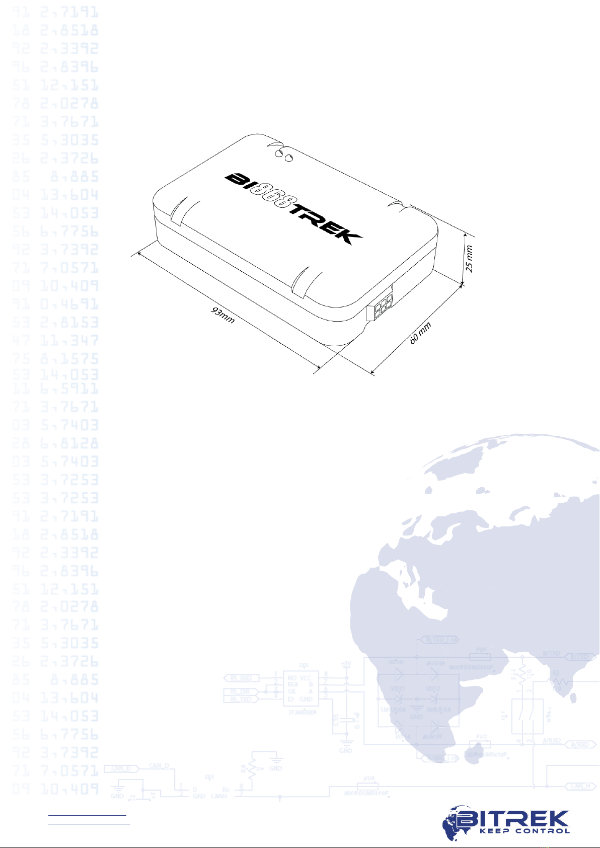
Dimensions (W хL хH)
93 х60 х25 mm
24
Net weight
120 g
25
Weight gross
130 g
26
Housing protection class
IP54
6
www.bitrek.com.ua
+380 44 507 02 07
Design of tracking device
Appearance and dimensions of the tracking device "BI-868 TREK
HW2" are shown in Figure 1.
Figure 1 - Appearance and design of the device.
Supply package
The tracking device "BI-868 TREK HW2" is provided with the
following set:
1. Tracking device "BI-868 TREK HW2" - 1 piece.
2. Connection cable - 1 piece.
3. Technical datasheet - 1 piece.
4. Warranty card - 1 piece.
5. Package box – 1 piece.
Preparation for operation, commissioning
SIM-card installation
To operate in GSM network device shall contain installed SIM-card
of Micro-SIM format. Phonebook of SIM-card shall remain empty, PIN-
code shall be removed (use of SIM-card with PIN-code can be allowed
subject to entering the PIN-code to the device settings).

7
www.bitrek.com.ua
+380 44 507 02 07
To install the SIM-card disconnect the power socket from the device,
remove the cover and install the SIM-card into the slot.
Connector for power supply and peripherals
The rear panel of the tracking device contains a socket for cable
connection. Connecting cable in turn has outlets for power, analog,
discrete sensors and actuating mechanisms. Location and numbering of
contacts are shown in Figure 2.
Marking of connector pins for power supply, sensors and peripherals
is shown in Table 2.
Figure 2 - Location and numbering of contact elements.
Table 2 - Designation of contact elements
No.
Color
Contact
name
Signal
type
Contact assignment
1
Violette
Out
Output
Digital output
2
Blue
DAT_high
Input
Digital input with active “1”.
Reserved for Ignition signal
3
Black
GND
Power
supply
Common cable (ground)
4
White
AN_in 1
Input
Analogue input No. 1
5
Grey
AN_in 2
Input
Analogue input No. 2
6
Red
+ V_in
Power
supply
"+" onboard power supply
(rated voltage 12 V or 24 V)
Assembly, commissioning
Assembly recommendations
Zone of installation of tracking device shall enable the connecting of
the pin to it and disable the possibility of accidental damage to the device,
moisture, impact of high temperature. Recommended location for
installation in the vehicle is an empty space under the dashboard inside
the vehicle; in addition, the device shall be placed in a way ensuring the
upper side with LEDs to face up.
8
www.bitrek.com.ua
+380 44 507 02 07
The body of the device contains grooves for easy fastening with
plastic ties.
Electrical connections
Power supply wires are laid through the maintenance holes in the
body of the vehicle from the regular battery location to the place of
installation of the tracking device. Power wires are connected to the
corresponding battery terminals.
Carrying out welding work during the repair of the vehicle
necessarily requires disabling of power socket and peripherals.
The active state for the discrete inputs with active "1" is to supply
to these inputs the voltage exceeding + 8 V. The passive state for these
inputs is the lack of connection ("in the air" input).
Analog input voltage can range from 0 V to 27 V.
The discrete outputs of the device are made according to the
scheme such as "Open collector". The load shall be connected to the gap
between the discrete output and "+" power of the on-board network.
When activated, the output gets ground switching. Maximum current of
the discrete output load shall not exceed 0.5 A. If it is needed to switch
higher currents, connect digital outputs via additional relay.
Analogue input voltage shall not exceed 27 V.
Device supply voltage shall not exceed 36 V. Otherwise the
device may be put out of action.
Device to computer connection
The tracking device can be connected to a PC, in order to configure
the device, as well as to perform maintenance works. For this purpose,
the device is equipped with a service UART output. To connect to a
computer, use an additional USB-UART converter, which can be
purchased from a dealer for an additional fee.
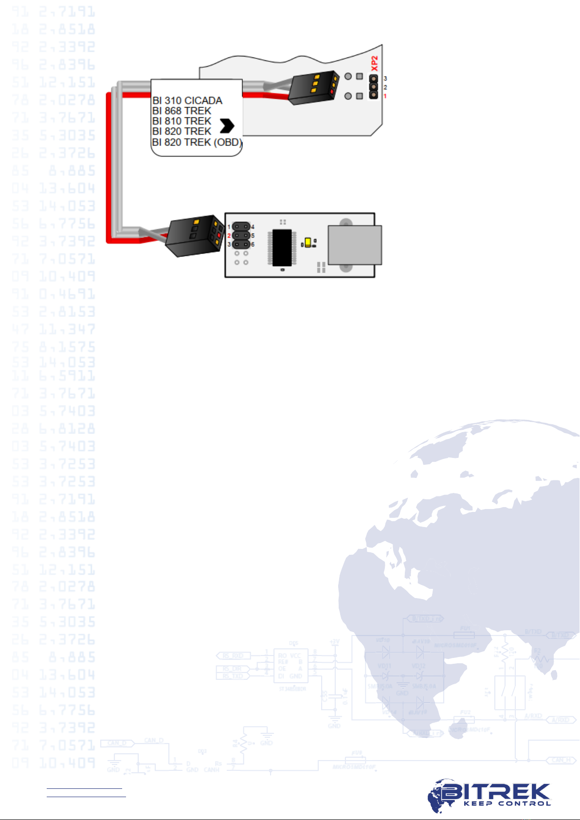
UART output socket is located on the board of the device. To access
the socket, remove the cover of the device. Procedure of connection of
USB-UART converter cable is shown in Figure 3.
9
www.bitrek.com.ua
+380 44 507 02 07
Figure 3 - Connection of the cable of USB-UART converter to the device
"BI-868 TREK HW2".
To work with the USB-UART converter, install the appropriate
device drivers. They can be downloaded from the official website:
http://www.ftdichip.com
To exchange data with the device, use a terminal program. Settings
of the terminal: speed - 115200 bit/second, data bit - 8, stop bit - 1, no
parity check, no flow control.
Once connected, the device will transmit data about its state to the
terminal. In addition, the user is able to use a terminal program to send
commands to a device and receive response to them. Send preliminary to
device the password to access the terminal in the following format:
TPASS: password;
, where password is a password for access to the device terminal
(default value is 11111).
Lifetime of access password after sending is 60 seconds.
After this time, re-send the password to exchange data with the
device.
Description of indication elements
Top panel of the tracking device contains two LEDs that indicate the
current status of the device.

10
www.bitrek.com.ua
+380 44 507 02 07
Table 3 - LEDs status
LED status
Red
Green
Lights up constantly
Connected to the
server and transferring
data
Satellites locked,
coordinates
determined
Not glow
-
No GPS signal
Blinks every 0.5 sec.
Not connected
-
Blinks every 0.2
seconds
Not connected, GSM
modem is in sleep
mode
-
Adjustment of "BI-868 TREK HW2" device
Basic information
The tracking device "BI-868 TREK HW2" can be configured in
following ways:
1. With a direct connection of the device to a computer.
2. Remotely, using SMS commands.
3. Remotely, using the configuration server.
Setting of the device through any of the available methods is limited
with the setting of the required values of the device parameters. Each
parameter has its own unique ID. Special commands are used to
read/record the values of selected parameter.
At remote configuration via SMS take into consideration that the
total length of the SMS shall not exceed 160 Latin characters. Number of
commands in SMS is limited to a maximum length of SMS.
All commands for the device are divided into control and
information commands.

11
www.bitrek.com.ua
+380 44 507 02 07
List of information commands to operate the device
Table 4 - List of information commands
No.
Command
Description
Availability
of response
1
getstatus
Information about current state of the
device
Yes
2
getgps
Current GPS coordinates and time of
device.
Yes
3
getmap
Request of device coordinates
Yes
4
getver
Request of the version of the device
software
Yes
5
getio
Read the value of the device's internal
sensors
Yes
6
flush
Request of device profile parameters
Yes
7
getparam
####
Read the value of the parameter by its
ID
Yes
Notes to Table 4
Information about current state of the device.
Command to be sent - getstatus;
Example of response: «Data Link: 1 GPRS: 1 IP: xxx.xxx.xxx.xxx GSM: 4
Roaming: 0»
, where:
Data link - current state of connection
(0 - not connected to server, 1 - connected to server);
GPRS - status GPRS (0 - not active, 1 - active);
IP - IP address of the device with an active GPRS connection; it is
assigned by the operator (not to be confused with the IP address of the
server);
GSM - level of GSM signal (1 - minimum, 5 - maximum);
Roaming - SIM-card in roaming (0 - home network, 1 - roaming).
Current GPS coordinates and time of device.
Command to be sent - getgps;
Example of response: «GPS: 1 Sat: 7 Lat: 50.2345 Long: 30.1652 Alt:
123 Speed: 0, Dir: 77 Date: 2019/2/15 Time: 14:37:32»
, where:
GPS - data status by GPS (1 - valid, 0 - invalid);
Sat - number of satellites visible to the device;
Lat - latitude (last known latitude);
Long - longitude (last known longitude);

12
www.bitrek.com.ua
+380 44 507 02 07
Alt - altitude, height above sea level
Speed - speed (km/hour);
Dir - direction of motion (degrees);
Date - current date
(1980/1/6 is transmitted in the absence of GPS-signal);
Time - current GMT time
(00:00:00 is transmitted in the absence of GPS-signal).
Request of device coordinates.
Command to be sent - getmap;
Example of response:
«www.biakom.com/maps/q=50.420209,30.428448,12,0»
Request of the version of the device software.
Command to be sent - getver;
Example of response: «BI-868v4 Ver: 2.9.2»
Read the values of the device's internal sensors.
Command to be sent - getio;
Example of response: «DH1: 0 DO1: 0 VPSV: 12996mV AIN1: 37mV
AIN2: 38mV»
, where:
DH1: 0 - current state of the discrete input;
DO1: 0 - current state of the discrete output;
VPSV - external power supply, millivolts;
VBAT –internal battery voltage, millivolts;
AIN1: 37mV AIN2: 38mV - analog inputs voltage, millivolts.
Request of device profile parameters.
Command to be sent - flush;
Example of response: «xxxxxxxxxxxxxxx, gps.utel.ua, none, none,
xxx.xxx.xxx.xxx, xxxxx 0»
, where:
IMEI (xxxxxxxxxxxxxxx) - identification number (IMEI) of the device;
APN (gps.utel.ua) - access point to connect GPRS
(shall be requested from the operator);
Login (none) - access login to GPRS

13
www.bitrek.com.ua
+380 44 507 02 07
(shall be requested from the operator, usually not required);
Password (none) - access password to GPRS
(shall be requested from the operator, usually not required);
IP (xxx.xxx.xxx.xxx) - Server IP address for data transmission;
PORT (xxxxx) - PORT of server for data transmission;
MODE (0) - mode of device operation (0 - TCP/IP connection).
Read the value of the parameter by its ID.
Command to be sent - getparam ####;
Parameter ID (####) consists of four digits and indicates the number of
the parameter. All configurable parameters are specified in the list of
device parameters (see Appendix 1 and Appendix 2).
Example of response: «Param ID #### Val: #»
, where:
Param ID - ID of requested parameters;
Val - current value of parameter.
Example of the command to request APN of the device (a parameter that
contains the APN device has ID 0242) - getparam 0242;
Example of response: «Param ID 0242 Val: gps.utel.ua».
List of control commands to operate the device
Table 5 - List of control commands
No.
Command
Description
Availability
of response
1
cpureset
Reload of device processor
No
2
rstallprof
Restoring of original state of profile
settings
No
3
deleterecords
Deletion of all saved records
No
4
setparam
####
Set the value of the parameter by
ID
Yes
5
boot #,#,#
Update of device software
Yes
6
setdigout #
Set the mode of operation of digital
output Out 1
Yes
7
ignitionoff
Activation of the safety locking of
ignition
Yes
8
ignitionon
Deactivation of the safety locking
of ignition
Yes

14
www.bitrek.com.ua
+380 44 507 02 07
Notes to Table 5.
Reload of device processor.
Command to be sent - cpureset;
No response is returned for this command. Receipt of the command
initiates a complete restart of all device processes.
Restoring of original state of profile settings.
Command to be sent - rstallprof;
No response is returned for this command. Receipt of this command
initiates reset of profile parameters to default ones.
Deletion of all saved records.
Command to be sent - deleterecords;
No response is returned for this command. Receipt of the command
deletes all the data packets from the device memory.
Set the value of the parameter by ID
Command to be sent - setparam ####;
Parameter ID (####) consists of four digits and indicates the number of
the parameter. All configurable parameters are specified in the list of
device parameters (see Appendix 1 and Appendix 2).
Example of response: «Param ID #### New Val: #»
, where:
Param ID - ID of parameter to be set up;
New Val - assigned value of parameter.
Example of the command to set APN of the device (a parameter that
contains the APN device has ID 0242) - setparam 0242 gps.utel.ua;
Example of response: «Param ID 0242 New Val: gps.utel.ua».
Update of device software.
Command to be sent - BOOT #,#,#;
Example of command to update the software:
«BOOT fw.bitrek.ua,80,*.bin;»
, where:
«HOST» - (fw.bitrek.ua,) - address of server locating the update files;
«PORT» - (80,) - port of server locating the update files;
«Firmware» - (*.bin;) - binary update file,
where * - the firmware version, .bin - file extension.

15
www.bitrek.com.ua
+380 44 507 02 07
This command allows remote software update of the device via GPRS
channel.
Note: Enable "download" for the SIM-card, and set the session timeout
not less than 10 seconds.
There are following responses at attempt to update the device software:
«BOOT: UPDATE DOWNLOAD OK» - successful update;
«BOOT: WAITE ERROR» - exceeded timeout at downloading software
update;
«BOOT: HOST CONNECT ERROR» - failure to connect to server with SW;
«BOOT: PAGE LOAD ERROR» - failure to load the file;
«BOOT: UPDATE DOWNLOAD ERROR» - failure to update the file.
Set the mode of operation of digital output Out 1.
Command to be sent - setdigout #;
Example of command for the activation of the output Out 1: setdigout 1;
The first digit in the command is Out 1 output state.
When it is necessary to activate the output, set the output value must to
"1". When it is necessary to deactivate the output, set the value to "0".
Activate/deactivate the safety locking of ignition.
Command to activate safe locking - ignitionon;
Command to deactivate safe locking - ignitionoff;
In case of activation of secure locking the discrete output Out 1 will be
activated if the speed according to GPS is less than 5 km/h.
Examples of response:
«Set RQS To Ignition On» - ignition switch on;
«Set RQS To Ignition Off» - ignition switch off;
Basic configuration
After installing the SIM-card of the mobile operator and connection
of the power supply, the device shall be configured to transmit data to
the server.
All adjustable parameters of the device are divided into groups:
Server and GPRS.
Tracking.
Security.
Service.
Voice communication.

16
www.bitrek.com.ua
+380 44 507 02 07
Roaming.
Setting required for basic operation of the device includes data
transmission and tracking. They are grouped in "Server and GPRS" and
"Tracking". After setting up the necessary parameters the device will
transmit data about its current location to the server.
All parameters available for configuration are specified in Appendix
1.
Security settings
To meet the safety conditions, access to the configuration of the
device can be limited.
At connection your device to the PC using USB-UART converter,
every time you send a command, the device requires the access
password. Standard access code is 11111. Lifetime of password is 60
seconds. After this timeout the password shall be re-entered. Access
password can be changed by the user (ID 0910, see Appendix 1)
Format of sending a standard password to the device - TPASS: 11111;
Examples of response:
«TASK COM TERM: PASSWORD OK» - correct password is entered;
«TASK COM TERM: INCORRECT PASSWORD» - incorrect password is
entered;
When sending commands via SMS, set the login and password of SMS
access. To set the login use ID 0252 parameter, to set the password use
ID 0253.
To set the login and password, any SMS command shall have the
following structure to be sent:
<Login><Password><Command1>;<Command2>;<Command3>;
Example of the command to be sent:
abcd 1234 getgps; getstatus;
In addition to the login and password, use the authorized phone
numbers. To record the telephone numbers in the memory device use the
parameters ID 0261 - ID 0269 (see Appendix 1). Total up to 9 phone
numbers can be applied. When using this function, the device will
respond to SMS from the stored in the memory authorized phone
numbers only.
If the login and password are set by SMS, they shall be specified in
each SMS with commands.

17
www.bitrek.com.ua
+380 44 507 02 07
Adjustment of I/O elements
The tracking device "BI-868 TREK HW2" is able to collect, process
and send to the server the data received from various sensors. Each
sensor is an I/O element and has a group consisting of 6 parameters for
setting. For example, to set the value of power supply voltage level to
the server, use group of parameters of
0410/0411/0412/0413/0414/0415.
These options have the following structure:
0410/0411/0412/0413/0414/0415
First 3 numbers (green) refer to parameter group number to
configure the I/O element.
Last number (gray) is a parameter number. 6 parameters (from 0
to 5) are available for a single I/O element. Possible values of these
parameters are presented in Table 6.

18
www.bitrek.com.ua
+380 44 507 02 07
Table 6 - List of parameters of I/O elements
Number
of
parameter
Description
Possible values
0
Enable/disable I/O
element
0 - disabled; 1 - enabled
1
Priority of I/O element at
transmission
0 - low; 1 - high
2
Upper limit
(depending on the type of I/O
element)
3
Lower limit
(depending on the type of I/O
element)
Setting of the type of the
generated event
1. entering the range;
2. leaving the range;
3. returning/leaving to/of
the range
monitoring;
4. monitoring + entering
the range;
5. monitoring + leaving the
range;
6. - monitoring +
returning/leaving to/of
the range;
7. generation of the event
to change the input value
to a predetermined
value;
8. - generation of the event
to change the input value
to a predetermined value
+ monitoring.
5
Averaging constant
From 0 and higher
Notes to Table 5:
Parameter 0 - on/off of transmission of I/O element to the server.
Parameter 1 - Priority: low/high. While selecting "Priority: low" - data of
the sensor will be sent to the server with the following data packet. While
selecting "Priority: high" data of the sensor will be sent to the server at
the earliest possible opportunity.
Parameter 2 - Upper limit - set the upper limit of the I/O element.
Parameter 3 - Lower limit - set the lower limit of the I/O element.
Parameter 4 - Set the type of the generated event:
0 - Returning to the range.
At a specific range of sensor values (range of values is specified as
follows - lower limit of the range is recorded to the corresponding

19
www.bitrek.com.ua
+380 44 507 02 07
parameter - "Lower limit", upper limit of the range is recorded to the
corresponding parameter "Upper limit"), the event will be generated
when the actual value of the sensor gets within the specified range.
In other cases, the event will not be created and the information will
not be sent to the server.
Example: The lower voltage limit is set to 0, the upper limit is set to
10 V (10 000 mV). Lowering the voltage below 10 V will generate
the event (see Figure 4).
PSV
U, mV
t, s
10 000
Figure 4 - Generation of event by returning to the range.
1 - Leaving the range.
The event will be generated if the actual sensor value is outside the
predetermined range.
Example: The lower voltage limit is set to 0, the upper limit is set to
10 V (10 000 mV). Rising of the voltage above 10 V will generate
the event (see Figure 5).
PSV
U, mV
t, s
10 000
Figure 5 - Generation of event by leaving the range.
2 - Returning/leaving to/of the range.
Event is generated every time when the actual value of the sensor is
out of the limits of the predetermined range.

20
www.bitrek.com.ua
+380 44 507 02 07
Example: The lower voltage limit is set to 5 V (5 000 mV) , the
upper limit is set to 10 V (10 000 mV). When the actual voltage
crosses limits of the specified range, then event is generated (see
Figure 6).
PSV
U, mV
t, s
10 000
5 000
Figure 6 - Generation of event by returning/leaving to/of the range.
3 - Monitoring. When this mode is selected, data will be transmitted
continuously, the events will not be generated.
4 - Monitoring + entering the range. When there is generated the
event after entering the range, the actual value of the sensor starts
to be transmitted to the server in the monitoring mode.
5 - Monitoring + leaving the range. When there is generated the
event after leaving the range, the actual value of the sensor starts to
be transmitted to the server in the monitoring mode.
6 - Monitoring + returning/leaving to/of the range. When one of the
events is generated, the actual value of the sensor starts to be
transmitted to the server.
7 - Change of the input value to a predetermined value. Changing of
the input value to the predetermined value in either direction will
cause the event generation. The value is recorded to the parameter
"Upper limit".
8 - Monitoring + change of the input value to a predetermined value.
When the event is generated, the actual value of the sensor starts to
be transmitted to the server.
Parameter 5 - Averaging constant. It is time required for I/O to be in a
certain state in order to generate an event. It is measured in milliseconds
(X*50 ms, i.e., while setting 10, the constant will be equal to 10*50=500
ms).
List of all I/O components of the device, available for configuration, is
provided in Appendix 2.
Table of contents
Other BITREK GPS manuals

BITREK
BITREK BI-810 TREK User manual

BITREK
BITREK BI 810 TREK User manual

BITREK
BITREK BI 868 TREK User manual

BITREK
BITREK BI-820OBD TREK User manual

BITREK
BITREK BI 530R TREK User manual

BITREK
BITREK BI-520L TREK User manual

BITREK
BITREK BI-530C TREK User manual

BITREK
BITREK BI-530P TREK User manual

BITREK
BITREK BI 820 TREK OBD User manual

BITREK
BITREK BI-910 TREK User manual
Popular GPS manuals by other brands


NorthStar
NorthStar 951X Operator's manual

Stars Navigation Technologies
Stars Navigation Technologies BT1.5 user manual

B.F. Goodrich
B.F. Goodrich stormscope wx-1000 pilot's guide

Icom
Icom GP-22 instruction manual

MGL Avionics
MGL Avionics EFIS G2 Guide to using

Spireon
Spireon FleetLocate FL18 quick start guide


