BITREK BI-910 TREK User manual

Research and Production Enterprise "DISC SYSTEMS" LTD
EDRPOU 16303375, a/c No.260075014037759
at PJSC "UKREXIMBANK" in c. Kyiv
MFO 380333, TIN 163033726585
www.bitrek.com.ua
[email protected]om.ua
+380 44 507 02 07
03061, Ukraine, c. Kyiv, 95-S Otradny ave., Telephone +38044 507 02 07. Fax +38044 507 02 02. www.bitrek.com.ua, sa[email protected]m.ua
Vehicles tracking device
BI-910 TREK
Operating Manual
Version 2019.09.1

2
www.bitrek.com.ua
[email protected]om.ua
+380 44 507 02 07
Table of Contents
Introduction...................................................................................................... 3
Safety Requirements for Installation and Maintenance of Tracking Device "BI-
910 TREK" .................................................................................................... 3
Transportation and Storage............................................................................. 3
Warranty ...................................................................................................... 3
Device ............................................................................................................. 3
Intended Use of the Device ............................................................................. 3
Principle of Operation ..................................................................................... 4
Specifications ................................................................................................ 4
Tracking device design ................................................................................... 5
Scope of Delivery........................................................................................... 6
Preparation for Operation ................................................................................... 6
Inserting SIM–Card ........................................................................................ 6
Sockets for Power Supply, Antennas, and Periphery Devices ............................... 7
Connection of the Power Supply, Discrete and Analog Sensors, as well as Extra
Devices ........................................................................................................ 8
Installation and Commissioning ......................................................................... 10
Installation Guide......................................................................................... 10
Electrical Connections................................................................................... 10
Connection to a Computer............................................................................. 11
Indicators Description................................................................................... 11
List of SMS Commands..................................................................................... 12
Structure of the SMS Commands ................................................................... 12
Configuring the Device ................................................................................. 13
Detailed Description of Information Commands ............................................... 15
Detailed Description of Controlling Commands................................................. 16
Basic Device Configuration ............................................................................ 18
Security Settings ............................................................................................. 18
Configuring I/O Components............................................................................. 19
Configuring Alarms .......................................................................................... 23
Switching Between the Profiles.......................................................................... 24
Description of Profile Switching...................................................................... 24
Description of Operator Selection Modes ......................................................... 24
Configuring Roaming Settings ........................................................................... 27
List of prohibited operators ............................................................................... 29
Configuring the Device for Operation with RFID Readers....................................... 29
Configuring the Device for Operation with Thermometers DS18B20 ....................... 29
Configuring the Device for Operation with Fuel Meter RS-485................................ 31
Use of Backup Server....................................................................................... 32
Configuring Engine Lock ................................................................................... 32
Addendum 1. Device parameters....................................................................... 34
Addendum 2. List of I/O components ................................................................. 47

3
www.bitrek.com.ua
[email protected]om.ua
+380 44 507 02 07
Introduction
Safety Requirements for Installation and Maintenance of
Tracking Device "BI-910 TREK"
Compliance with the safety precautions is the responsibility of
technical personnel installing the tracking device, as well as employees in
charge of equipment on site.
To avoid damage to the device, please, keep it in a stress-resistant
case. Before using the device, please, place it so that its status LED
indicators are clearly visible. Prior to dismantling outputs of the device,
please, disconnect its power supply unit.
Transportation and Storage
The tracking device in the manufacturer's package can be
transported by any closed land and sea transport mode (in railroad cars,
containers, closed trucks, cabins, etc.). It can also be transported in
heated aircraft cabins.
When transporting and storing the device, the package instructions
on the labels must be observed.
Warranty
The warranty period for the tracking device shall be 12 months of
the date of commissioning. The commissioning date must be recorded
per requirements set forth in the certificate for the tracking device; if no
such data are available in the certificate, the warranty period shall be
counted starting with the tracking device shipment to the customer.
Manufacturer's warranty shall only be valid provided that the
customer complies with the requirements of this Manual. In the event of
their violation, or in the presence of mechanical or electrical damage
caused by the factors that are not covered in this Manual, the Warranty
shall be deemed void.
Device
Intended Use of the Device
Tracking device BI-910 TREK is used for navigation tasks, remote
control and monitoring of a vehicle or other remote object.
The tracking device is intended for installation to any mobile or
remote stationary object in order to:
determine geographical coordinates, speed and direction of
movement;
collect data coming from the external devices;
control actuators;
voice communication;
transfer the data to a dispatch center.

4
www.bitrek.com.ua
[email protected]om.ua
+380 44 507 02 07
GSM 900/1800 or GSM 850/900/1800/1900 mobile carrier network
is used as a medium for data transfer. To determine the coordinates,
NAVSTAR GPS system is used. To detect vehicle movement, the data
obtained from GPS or GPS/GLONASS and internal acceleration meter are
used.
The device must be installed in a spot unavailable to a driver.
Principle of Operation
In real time, the tracking device:
using an in-built GPS or GPS/GLONASS receiver, determines the
location and motion parameters of an object (time, geographical
coordinates, speed, direction of travel);
collects and processes information coming from analog and
discrete sensors;
controls actuators upon the command from the operator panel.
The data obtained are recorded and stored in the internal log that
is based on a non-volatile memory chip. Records from this log are
transferred to the operator panel through a GSM channel with a
predetermined frequency or on an event basis. Information exchange is
done via GPRS and SMS. Voice communication is also supported.
On-line terminal operation is only possible provided there is GSM
coverage. Beyond the GSM network coverage area, the tracking device is
in the mode of a "black box", i.e. it records all logged information to the
non-volatile memory and transfers it when a vehicles enters into a GSM
coverage area.
Specifications
Table 1. Device Specifications
No.
Item
Specifications
1
Data transfer standard
GSM 900/1800 or GSM
850/900/1800/1900
2
GSM network communication channel
GPRS, SMS, voice
communication
3
GPRS grade
10
4
GPS and GSM antennae
External
5
Navigation system types
GPS or GPS/GLONASS
6
Auxiliary digital protocol
RS-485, 1Wire, CAN
(FMS)
7
Motion sensor
Acceleration meter
8
Secure power supply input
yes
9
Number of SIM cards
2
10
Number of 0-active discrete inputs
4

No.
Item
Specifications
11
Number of 1-active discrete inputs
2
12
Number of discrete outputs
2
13
Discrete inputs voltage range
from 0 V to 40 V
14
Type of discrete outputs
open collector
15
Full-load amperage of discrete outputs
0.5 А
16
Number of analog inputs
2
17
Analog input voltage range
from 0 V to 27 V
18
Power
DC
19
Voltage
from 6 v to 40 V
20
Normal current (12 V)
60 mA
21
Max. current (12 V)
300 mA
22
Microphone
Electrete
23
Microphone load resistance
2.2 kOhm
24
Outer speaker resistance
≥ 8 Ohm
25
Non-volatile memory capacity
2 MB (or 65,000 entries)
26
Internal battery Li-Ion
1,000 mAh
27
Operating temperature
from -30 °С to +80 °С
28
RH
80 ± 15 %
29
Dimensions (W х L х H)
125 х 95 х 33
30
Weight
200 g
31
Body
IP 65 (plastic РА 6)
32
Connection (cable)
IP 68
Tracking device design
Fig. 1. Appearance and Dimensions of Tracking Device BI-910 TREK.
(General view)

6
www.bitrek.com.ua
[email protected]om.ua
+380 44 507 02 07
Fig. 2. Appearance and Dimensions of Tracking Device BI-910 TREK.
(Rear view)
Scope of Delivery
1. Tracking Device BI-910 TREK - 1 pc.
2. GPS antenna –1 pc.
3. GSM antenna –1 pc.
4. Connection cable - 1 pc.
5. Certificate –1 pc.
6. Warranty sheet –1 pc.
7. Packing box –1 pc.
Preparation for Operation
Inserting SIM–Card
To operate on a GSM network, at least one SIM-card has to be
inserted into the device. The second SIM-card is optional and can be used
for an alternative carrier network in areas with no primary carrier's
coverage. Contacts of the SIM-card must not be saved, PIN-code must be

7
www.bitrek.com.ua
[email protected]om.ua
+380 44 507 02 07
disabled (a SIM-card with an enabled PIN-code can be used provided that
the PIN-code has been entered into the device settings).
To insert a SIM-card all device connectors must be disconnected
and its top cover must be removed. There are 2 slots on the top of the
circuit board. The SIM-card selected by default shall be inserted to slot 1
(SIM1). Then the device has to be reassembled in the reversed order.
ATTENTION! The manufacturer does not supply a SIM-
card necessary for connecting to a GSM network! You can
purchase a SIM-card from a local GSM carrier!
Sockets for Power Supply, Antennas, and Periphery
Devices
The front panel of the tracking device contains antennae
connectors, while its rear panel contains power supply connector,
discrete and analog sensors, actuators and headset connectors. For
antennae connection, SMA inlets are used. The locations of the inlets is
shown in Figure 3.
Fig. 3. Appearance and Antennae Connectors Legends on Tracking Device
BI-910 TREK
To connect to the power supply socket, sensors and actuators, IP
68 connector socket is used. Location of power supply socket is shown in
Figure 4.
8
www.bitrek.com.ua
[email protected]om.ua
+380 44 507 02 07
Fig. 4. Location of the Socket and Numbers of Pins
Connection of the Power Supply, Discrete and Analog
Sensors, as well as Extra Devices
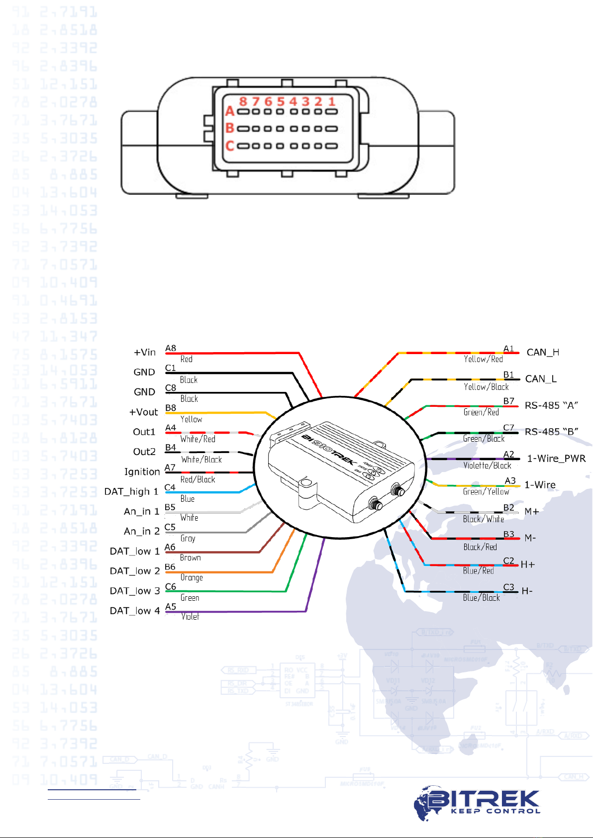
Fig. 5. BI-910 TREK Contact Pins

No.
Color
Pin legend
Signal
Pin purpose
А1
Yellow/Red
CAN_H
Input/Output
CAN_H signal from the
CAN bus
А2
Violette /
Black
1-
Wire_PWR
Power
Output +3.3 V for device
power supply "1-Wire"
(15 mA max)
А3
Green/
Yellow
1-Wire
Input/Output
1-Wire interface data
signal
А4
White/Red
DOut 1
Output
Discrete output No.1
А5
Violette
DAT_low 4
Input
0-active discrete input
А6
Brown
DAT_low 1
Input
0-active discrete input
А7
Red/Black
Ignition
Input
1-active discrete input -
spared for ignition
А8
Red
+ Vin
Power
"+" on-board power
terminal (nominal voltage
is 12 VDC or 24 VDC)
B1
Yellow/
Black
CAN_L
Input/Output
CAN_L signal from the
CAN bus
B2
Black/White
M +
Input
Mic "+" input
B3
Black/Red
M -
Input
Mic "-" input
В4
White/Black
DOut 2
Output
Discrete output No.2
B5
White
An_in 1
Input
Analog input No.1
B6
Oragnge
DAT_low 2
Input
0-active discrete input
B7
Green/Red
A
Input/Output
"А" signal RS-485
B8
Yellow
+ Vout
Power
Secure power input for
extra sensors.
Voltage is + Vin.
Max. current is 300 mA.
C1
Black
GND
Power
Ground (earth)
C2
Blue/Red
H +
Output
Speaker output "+"
C3
Blue/Black
H -
Output
Speaker output "-"
C4
Blue
DAT_high 1
Input
1-active discrete input
C5
Gray
An_in 2
Input
Analog input No.2
C6
Green
DAT_low 3
Input
0-active discrete input
C7
Green/Black
B
Input/Output
"B" signal RS-485
C8
Black
GND
Power
Ground (earth)

10
www.bitrek.com.ua
[email protected]om.ua
+380 44 507 02 07
Installation and Commissioning
Installation Guide
Tracking device location must ensure connections of sockets and
avoid potential of accidental damage; it also must eliminate exposure to
direct sunlight, moisture, etc. Recommended location of installation in a
vehicle is the empty space under the dashboard inside a vehicle.
GPS and GSM antennae shall also be located in the empty space
under the dashboard of a vehicle.
Antennae cables must be located and clamped along the entire
length with straps clamped to the clamping sites. Cabling must be done
so as to avoid any damage during the operation, when closing
doors/hatches.
Electrical Connections
Power cable shall be passed through special ports in a vehicle body
from the normal battery location to the location where the tracking
device is to be installed. Power cables shall be connected to respective
battery terminals.
ATTENTION! When performing welding operations during
repairs of a vehicle, MAKE SURE to disconnect power cable
and periphery cables!
Discrete inputs with active "0" respond to connection of these
inputs to GND (ground). This input is inactive when it is not connected
(input is 'blank').
Discrete inputs with active "1" respond to the voltage of over 8 V
on them (connection of the input to the "+" terminal of vehicle network).
This input is inactive when it is not connected (input is 'blank').
Voltage on the analog input may vary from 0 to 24 VDC.
Discrete outputs are "open collector" type. Load must be connected
into the open between the discrete output and power supply "+"
terminal. When the output is activated it closes to the GND. Max. load
current of the discrete output should not exceed 0.5 А! If high-amperage
currents need to be switched, the discrete outputs must be connected
using additional relay.
ATTENTION! Voltage on the discrete inputs and outputs
should not exceed 30 V.
Voltage on the analog inputs should not exceed 30 V.
Device input voltage should not exceed 36 V.
Otherwise, the device can be damaged.

11
www.bitrek.com.ua
[email protected]om.ua
+380 44 507 02 07
Connection to a Computer
The tracking device can be connected to a computer for
configuration and servicing. The device has UART output interface for
that purpose. In order to connect the device to a computer a USB-UART
adapter should be used that can be purchased from the dealer as an
option.
Fig. 6. BI-910 TREK Connection Diagram
A terminal program can be used for data exchange with the device.
Terminal configuration settings: bit rate –115,200 bps, data bit –8, stop
bit –1, without parity check, without stream control.
Once the link is up, the device will start sending its status data to
the terminal. Using the terminal program, a user can send commands to
the device and receive responses to them. But the device first needs to
send access password to the terminal in the following format:
TPASS: password;
where password is an access password for the terminal (by default,
11111 is used).
Once sent, the password will be valid for 60 seconds. After this
timeout, the password needs to be sent again so that the data can be
exchanged with the device.
Indicators Description
The top panel of the tracking device has 3 LEDs that indicate
current status of the device.

No.
LED mode
Red
Yellow
Green
1
Permanently
on
External
power is on
The devices is
connected to the
server and the data
are transmitted
-
2
Off
No external
power
-
No satellites
available
3
Blinks once
every 0.5
seconds
-
Trying to connect
to the server
4
Blinks once
every 0.1
seconds
-
Failure to connect
to the server, the
attempt will be
repeated in 2
minutes
-
5
Blinks once
every 2
seconds
-
-
Satellites are
available,
coordinates
have been
established
List of SMS Commands
SMS commands are used for getting current state of the device,
troubleshooting potential errors, configuring the settings, etc. An SMS
command should be sent together with login and password; the sender's
number must be included to the list of authorized contacts (when such
list is used).
Structure of the SMS Commands
Any SMS with commands includes login/password pair (when
configured) and a list of different commands. The commands are
delimited with semicolon delimiter.
SMS commands entered to the tracking device should be of the
following format:
<login><password><command1>;<command2>;<commandN>;
Example of an SMS command:
abcd 1234 getgps; getstatus;
ATTENTION! Total length of an SMS command string
should not exceed 160 Latin characters. Number of
commands per one SMS is only limited by the maximum
length of an SMS.
It is also essential to observe the order of the commands, when
they are sent in one SMS message. The device reads and performs the

13
www.bitrek.com.ua
[email protected]om.ua
+380 44 507 02 07
commands in sequential order. E.g.: once the cpureset; command is
received the device processor will reset and the commands will not be
further performed.
Correct:
setparam 0242 <APN>;
setparam 0245 <HOST>;
setparam 0246 <PORT>;
cpureset;
Incorrect:
setparam 0242 <APN>;
cpureset;
setparam 0245 <HOST>;
setparam 0246 <PORT>;
When login and passwords pairs are configured for access using
SMS, they must be included to each SMS with the commands. If a
login/password pair is enabled, but not included to an SMS with the
commands, such SMS will be ignored. If a login/password pair option is
not enabled, it will not be checked.
In the event that one of the authorized phone numbers is enabled,
SMS commands will only be performed provided that they have been
sent from one of the authorized phone numbers (login/password is also
required, if enabled). If there is no authorized phone number enabled,
SMS with commands will be received from any phone number.
Configuring the Device
The BI-910 TREK Tracking Device can be configured by one of the
methods below:
1. Using a direct connection between the device and a computer.
2. Remotely, using SMS commands.
Configuration of the device by any of the methods available only
requires configuring necessary device parameters. Each parameter has its
own unique ID. Special commands are used to read/record the values of
a selected parameter.
In case of remote configuration of the device using SMS, one
should bear in mind that the total length of an SMS should not exceed
160 Latin characters. Number of commands per one SMS is only limited
by the maximum length of an SMS.
All commands for device manipulation can be divided into the
controlling and information ones.

No.
Command
Description
Response
1
getstatus
Information about current
device status
yes
2
getgps
Current GPS coordinates and
time of the device
yes
3
getmap
Request for the link with
device coordinates
yes
4
getver
Request for device firmware
version
yes
5
getio
Getting the readings from
internal device sensors
yes
6
flush
Request for device profile
parameters
yes
7
getparam
####
Get a parameter by its ID
yes
Table 4. List of Controlling Commands
No.
Command
Description
Response
1
cpureset
Reset of the device CPU
none
2
rstallprof
Reset to default profile
parameters
none
3
deleterecords
Deletion of all records saved
none
4
setparam
####
Set a parameter by its ID
yes
5
boot #,#,#
Update of device firmware
yes
6
setdigout ##
Set operating modes for
digital outputs Out 1 and Out
2
yes
7
ignitionoff
Disabling safety lock with the
ignition
yes
8
ignitionon
Enabling safety lock with the
ignition
yes

15
www.bitrek.com.ua
[email protected]om.ua
+380 44 507 02 07
Detailed Description of Information Commands
Retrieval of current status of the device –getstatus;
No.
Parameter
name
Description
1
Data Link
Current link status between the device
and server: 0 –link down, 1 –link up
2
GPRS
GPRS status: 0 –not connected, 1 –
connected
3
GPRS IP
IP address of the device when GPRS-
connected
4
GSM
GSM signal level [0-5]
5
Roaming
0 –home network, 1 –roaming
network
Example of a response:
Data Link: 1 GPRS: 1 IP: 46.133.143.201 GSM: 5 Roaming: 0
Retrieval of current location of the device –getstatus;
No.
Parameter
name
Description
1
GPS
Valid data - 1; Invalid data - 0
2
Sat
Number of visible satellites
3
Lat
Latitude (previous known latitude)
4
Long
Longitude (previous known longitude)
5
Alt
Altitude, m
6
Speed
Speed, km/h
7
Dir
Direction, degrees
8
Date
Date
9
Time
Current GMT time
Example of a response:
GPS: 1 Sat: 7 Lat: 50.2535 Long: 30.2622 Alt: 147 Speed: 0 Dir: 77
Date: 2018/4/30 Time: 12:33:45
Command of request for link with device coordinates –getmap;
Example of a response:
"www.biakom.com/maps/q=50.420209,30.428448,12,0"
Command of request of device firmware version –getver;
Example of a response:
BI-910 VER 3.16.7

No.
Parameter
name
Description
1
DI#
Digital input status
2
DO#
Digital output status
3
AI#
Analog input status
Example of a response:
DL1: 0 DL2: 0 DL3: 0 DL4: 0 DH1: 0 DH2: 0 DO1: 1 D02: 0 AIN1: 0 mV
AIN2: 0 mV PSV: 12.234 mV VBAT:4.186 mV
Request for device profile parameters –flush;
No.
Parameter
name
Description
1
IMEI
Modem ID number
2
APN
GPRS access point
3
LOGIN
GPRS access login
4
PASS
GPRS access password
5
IP
IP address of the server
6
PORT
Server port
7
MODE
Operating mode (always = 0 - TCP/IP)
Example of a response:
353976012555151, internet, none, none, 212.47.99.62, 12050, 0
Get the readings by parameter ID –getparam ####;
ID consists of 4 digits –the first digit is a profile number, the last three
specify ID of a parameter.
Example of a command => request value of ID=242 parameter from
profile 0: getparam 0242;
No.
Parameter
name
Description
1
Param ID
Profile number and parameter ID
2
Value
Parameter value
Example of a response to the "getparam 0242" command:
Param ID 0242 Val: internet
Detailed Description of Controlling Commands
Command of complete device CPU reset –cpureset;
There is no response to this command. Once the command is received,
all processes of the device reset.

17
www.bitrek.com.ua
[email protected]om.ua
+380 44 507 02 07
Restoration of profile parameters defaults –rstallprof;
There is no response to this command. Once the command is received,
all profile parameters are restored to their default values.
Command for deletion of all records saved –deleterecords;
There is no response to this command. Once the command is received,
all data packets are removed from the device memory.
Set parameter values by their ID - setparam #### #;
ID consists of 4 digits –the first digit is a profile number, the last three
specify ID of a parameter (refer to Addendum 1).
Example of a command => set value of ID=242 parameter from profile
0:
setparam 0242 www.kyivstar.net
No.
Parameter
name
Description
1
Param ID
Profile number and parameter ID
2
New Value
New value of a parameter
Example of a response to the "setparam 0242 www.kyivstar.net"
command - setting an APN:
Param ID 0242 New Val: www.kyivstar.net
Device firmware update - BOOT #,#,#;
Command parameters:
HOST –IP address of the server containing the update;
PORT –Port of the server containing the update;
PATH –Path to the firmware update file on the server;
Example of the command:
BOOT fw.bitrek.ua,80,*.bin;
Where * is a version of the firmware, .bin –file format extension.
Options of response to the attempted update download:
BOOT: UPDATE DOWNLOAD OK –downloading was a success;
BOOT: WAITE ERROR –wait timeout was exceeded during update
download;
BOOT: HOST CONNECT ERROR –failed to connect to the server;
BOOT: PAGE LOAD ERROR –failed to download the file;
BOOT: UPDATE DOWNLOAD ERROR –failed to update the firmware;
Setting operating modes of digital outputs OUT1 and OUT2 -
setdigout ##;
Example for enabling Out 1: setdigout 10;
Example for enabling Out 2: setdigout 01;
The first digit in the command is Out 1 status, the second one is Out 2
status.
When the output needs to be enabled, its value must be set to "1".

18
www.bitrek.com.ua
[email protected]om.ua
+380 44 507 02 07
When the output needs to be disabled, its value must be set to "0".
No.
Parameter
name
Description
1
DOx New Val: y
When OUTx status changes
2
DOx Old Val: y
When OUTx status does not change
Example of an SMS response:
DO1 Old Val: 0 DO2 New Val: 1
Basic Device Configuration
Once a mobile carrier SIM-card is inserted and power supply is
connected, the device needs to be configured for transferring data to the
server. When the Bitrek Configurator is used, all configuration settings
will be divided into groups:
Server and GPRS
Tracking
Safety
Service
Voice communication
Roaming
The settings required for the basic operation of the device include
data transfer and tracking settings. They are included to the "Server &
GPRS" and "Tracking" groups. Once the appropriate settings are
configured, the device will start transmitting the data of its current
location to the server.
All configurable settings are given in Addendum 1.
Security Settings
To comply with the security regulations, access to the device
configuration settings may be restricted.
When connecting the device to a computer by means of USB-UART
adapter, the device access password must be entered every time, when
sending the commands to the device.
Default password is 11111. The password is valid for 60 seconds
once sent. Once this time lapses, the password needs to be entered
again. Access password can be changed by a user.
The default password must be sent to the device in the following format –
TPASS: 11111;
Example of a response:
"TASK COM TERM: PASSWORD OK" –the password is correct;
"TASK COM TERM: INCORRECT PASSWORD" –the password is
incorrect;

19
www.bitrek.com.ua
[email protected]om.ua
+380 44 507 02 07
When sending the commands using SMS, access login and
password can be enabled. To set login, the ID 0252 parameter is used,
while for the password the ID 0253 is used.
When login and password are enabled, any SMS command should
have the following structure before sending it:
<Login><Password><Command1>;<Command2>;<Command3>;
Example of a command: abcd 1234 getgps; getstatus;
Apart from setting a login and a password, authorized phone
numbers can be used. To record phone number to the device memory,
the ID 0261 –ID 0269 parameters are used (refer to Addendum 1). In
total, up to 9 phone numbers are supported by the device. If this feature
is used, the device will receive only SMS from the authorized phone
numbers saved to its memory.
If SMS login and password are enabled, they must be included in
each SMS with the commands.
Configuring I/O Components
The BI-910 TREK Tracking Device can collect, process and send
data obtained from different sensors to the server. Each sensor is an I/O
component and has a group consisting of 6 parameters for configuration.
E.g., to configure data transfer of voltage level from the power
supply unit to the server the ID 0410/0411/0412/0413/0414/0415
parameter group is used. These parameters have the following structure:
0410/0411/0412/0413/0414/0415
The first three digits (highlighted with green) specify the number of the
group of parameters for configuration of an I/O component.
The last digit (highlighted with gray) is a parameter number. There
are 6 parameters (from 0 to 5) per an I/O component. Possible values for
these parameters are shown in Table 5.

20
www.bitrek.com.ua
[email protected]om.ua
+380 44 507 02 07
Table 5. List of Parameters for I/O Components
Parameter
No.
Description
Possible values
0
Enabling / disabling
an I/O component
0 –disabled; 1 - enabled
1
Priority of an I/O
component during
sending
0 –low; 1 - high
2
Upper threshold
(depends on I/O component
type)
3
Lower threshold
(depends on I/O component
type)
4
Setting the type of
trigger event
0 –going within range;
1 –going beyond range;
2 –going back within/beyond
range;
3 –monitoring;
4 –monitoring + going within
range;
5 –monitoring + going beyond
range;
6 –monitoring + going
within/beyond range;
7 –event generation by change
of an input by a preset value;
8 –event generation by change
of an input by a preset value +
monitoring.
5
Averaging constant
0+
Clarifications to Table 5:
Parameter 0 –enabling / disabling I/O component transmission to the
server.
Parameter 1 - Priority: low/high. When selecting the "Priority: low"
option, the data from the sensor will be sent to the server with the next
data packet. When selecting the "Priority: high" option, the data will be
sent to the server whenever possible;
Parameter 2 - Upper threshold –setting the upper threshold of the I/O
component;
Parameter 3 - Lower threshold –setting the lower threshold of the I/O
component;
Table of contents
Other BITREK GPS manuals

BITREK
BITREK BI-868 TREK HW2 User manual

BITREK
BITREK BI 530R TREK User manual

BITREK
BITREK BI-520L TREK User manual

BITREK
BITREK BI-530C TREK User manual

BITREK
BITREK BI-820OBD TREK User manual

BITREK
BITREK BI-810 TREK User manual

BITREK
BITREK BI 868 TREK User manual

BITREK
BITREK BI 820 TREK OBD User manual

BITREK
BITREK BI-530P TREK User manual

BITREK
BITREK BI 810 TREK User manual
Popular GPS manuals by other brands


Shenzhen v-sun Electronics
Shenzhen v-sun Electronics TLT-1C instruction manual

TomTom
TomTom START reference guide

Binatone
Binatone F350 - EDITION 5 user guide

Garmin
Garmin nuvi 205W Series Manuel d'utilisation

Omnitracs
Omnitracs MCP100 installation guide

TeeJet Technologies
TeeJet Technologies MATRIX PRO GS user manual


