BITREK BI-820OBD TREK User manual

OOO NPP "DISC SYSTEMS"
EDRPOU 16303375, a/c No. 260075014037759
in PAO "UKREKSIMBANK" in Kiev
MFO 380333, INN 163033726585
www.bitrek.com.ua
[email protected]om.ua
+380 44 507 02 07
95-C Otradny Prospekt, Kiev, 03061, Ukraine, phone +38044 507 02 07, fax 038044 507 02 02 www.bitrek.com.ua, s[email protected]m.ua
Phone +38044 507 02 07. Fax +38044 507 02 02. www.bitrek.com.ua,
Vehicles Tracking Device
BI-820OBD TREK
Operating Manual
Version 2018.11.1

2
www.bitrek.com.ua
[email protected]om.ua
+380 44 507 02 07
Table of Contents
Introduction............................................................................................3
Safety Requirements for Installation and Maintenance of Tracking
Device "BI-820OBD TREK".....................................................................3
Transportation and Storage ...................................................................3
Warranty............................................................................................. 3
Device.................................................................................................... 3
Intended Use of the Device.................................................................... 3
Principle of Operation ...........................................................................4
Specifications ......................................................................................4
Tracking device design..........................................................................5
Scope of Delivery .................................................................................6
Preparation for Operation .........................................................................6
Inserting SIM–Card ..............................................................................6
Contact assignment .............................................................................. 7
Installation and Commissioning .................................................................7
Installation Guide .................................................................................7
Connection to a Computer ..................................................................... 8
Indicators Description ........................................................................... 9
List of SMS Commands.............................................................................9
Structure of the SMS Commands............................................................9
Configuring the Device........................................................................ 10
Detailed Description of Information Commands ...................................... 12
Detailed Description of Controlling Commands ....................................... 13
Basic Device Configuration .................................................................. 15
Security Settings ................................................................................... 15
Configuring I/O Components................................................................... 16
Configuring Alarms ................................................................................ 20
Description of Operator Selection Modes................................................... 21
Configuring Roaming Settings ................................................................. 21
Use of Backup Server............................................................................. 23
Addendum 1. Device parameters ............................................................. 24
Addendum 2. List of I/O Components....................................................... 31
Addendum 3. List of available OBD-II parameters...................................... 35

3
www.bitrek.com.ua
[email protected]om.ua
+380 44 507 02 07
Introduction
Safety Requirements for Installation and Maintenance of
Tracking Device "BI-820OBD TREK"
Compliance with the safety precautions is the responsibility of
technical personnel installing the tracking device, as well as employees in
charge of equipment on site.
To avoid damage to the device, please, keep it in a stress-resistant
case. Before using the device, please, place it so that its status LED
indicators are clearly visible. Prior to dismantling outputs of the device,
please, disconnect its power supply unit.
Transportation and Storage
The tracking device in the manufacturer's package can be
transported by any closed land and sea transport mode (in railroad cars,
containers, closed trucks, cabins, etc.). It can also be transported in
heated aircraft cabins.
When transporting and storing the device, the package instructions
on the labels must be observed.
Warranty
The warranty period for the tracking device shall be 12 months of
the date of commissioning. The commissioning date must be recorded
per requirements set forth in the certificate for the tracking device; if no
such data are available in the certificate, the warranty period shall be
counted starting with the tracking device shipment to the customer.
Manufacturer's warranty shall only be valid provided that the
customer complies with the requirements of this Manual. In the event of
their violation, or in the presence of mechanical or electrical damage
caused by the factors that are not covered in this Manual, the Warranty
shall be deemed void.
Device
Intended Use of the Device
Tracking device BI-820OBD TREK is used to solve problems of
navigation and control over the transport standard. The device is
intended for use on moving objects equipped with OBD-II diagnostic
connector and is used to solve problems:
• Determination of geographic coordinates, speeds and directions of
movement;
• Data collection from the on-board computer of cars through the
OBD-II interface;

4
www.bitrek.com.ua
[email protected]om.ua
+380 44 507 02 07
• Data transfer to a server for processing data processing in
specialized software.
GSM 900/1800 mobile or GSM 850/900/1800/1900 carrier network
is used as a medium for data transfer. To determine the coordinates,
NAVSTAR GPS system is used. To detect vehicle movement, the data
obtained from GPS or GPS/GLONASS and internal acceleration meter are
used.
Principle of Operation
In real time, the tracking device:
using an in-built GPS or GPS/GLONASS receiver, determines the
location and motion parameters of an object (time, geographical
coordinates, speed, direction of travel);
• determines with the help of the built-in GPS or GPS / GLONASS
receiver of the data and time of the object (time, geographical
coordinates, speed, direction of movement);
• collects and processes information from the on-board computer
of the car;
The data obtained are recorded and stored in the internal log that
is based on a non-volatile memory chip. Records from this log are
transferred to the operator panel through a GSM channel with a
predetermined frequency or on an event basis. Information exchange is
done via GPRS and SMS. Voice communication is also supported.
On-line terminal operation is only possible provided there is GSM
coverage. Beyond the GSM network coverage area, the tracking device is
in the mode of a "black box", i.e. it records all logged information to the
non-volatile memory and transfers it when a vehicles enters into a GSM
coverage area.
Specifications
Table 1. Device Specifications
Item
Specification
Data transfer standard
GSM 900/1800 or GSM
850/900/1800/1900
GSM network communication
channel
GPRS, SMS
GPRS klass
10
GPS and GSM antennas
Внутренние
Navigation system type
GPS или GPS/ГЛОНАСС
Connection standard to the onboard
computer of the vehicle
OBD-II

Item
Specification
Motion sensor
Accelerometer
Number of SIM cards
1
Supported protocols
ISO 15765-4 (CAN);
ISO 14230-4 (KWP2000);
ISO 9141-2 (Asian, European,
Chrysler vehicles)
Voltage
12 V or 24 V
Normal input current (12 V)
60 mA
Max. current (12 V)
350 mА
Non-volatile memory capacity
2 MB (65 000 records)
Internal battery Li-Ion
1 000 mАh
Operating temperature
От -30°С до +80°С
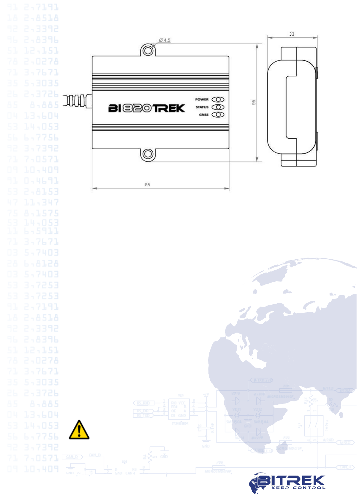
Dimensions (W х L х H)
85 х 95 х 33 mm
Weight
200 gr.
Housing protection class
IP65
Tracking device design
Fig. 1. Appearance and Dimensions of Tracking Device BI-820OBD TREK.
6
www.bitrek.com.ua
[email protected]om.ua
+380 44 507 02 07
Scope of Delivery
1. Tracking Device BI-820OBD TREK - 1 pc.
2. Certificate –1 pc.
3. Warranty sheet –1 pc.
4. Packing box –1 pc.
Preparation for Operation
Inserting SIM–Card
To operate on a GSM network, a SIM-card has to be inserted into
the device. Contacts of the SIM-card must not be saved, PIN-code must
be disabled (a SIM-card with an enabled PIN-code can be used provided
that the PIN-code has been entered into the device settings).
To insert a SIM-card all device connectors must be disconnected
and its top cover must be removed. There is a slot on the top of the
circuit board. Then the device has to be reassembled in the reversed
order.
ATTENTION! The manufacturer does not supply a SIM-
card necessary for connecting to a GSM network!

7
www.bitrek.com.ua
[email protected]om.ua
+380 44 507 02 07
Contact assignment
Fig. 2. BI-820OBD TREK Contact Pins
87654321
16 15 14 13 12 11 10 9
Table 2. Pin legends
Pin
number
Pin
legend
Signal type
Purpose
4
P-GND
Power
Common wire (ground)
5
GND
Power
Signal ground
6
CAN-H
Input/Output
«CAN_H» signal
(J-2284)
7
K Line
Input/Output
Data transmission/reception line
(SAE)
14
CAN-L
Input/Output
«CAN_L» signal
(J-2284)
15
Line ISO
Input/Output
Diagnostic line
(SAE)
16
+Vin
Power
"+" on-board power terminal
(nominal voltage is 12 VDC or 24
VDC)
Installation and Commissioning
Installation Guide
Tracking device location must ensure connections of OBD-II sockets
and avoid potential of accidental damage; it also must eliminate
exposure to direct sunlight, moisture, etc.

8
www.bitrek.com.ua
[email protected]om.ua
+380 44 507 02 07
Cables must be located and clamped along the entire length with
straps clamped to the clamping sites. Cabling must be done so as to
avoid any damage during the operation, when closing doors/hatches.
Connection to a Computer
The tracking device can be connected to a computer for
configuration and servicing. The device has UART output interface for
that purpose. In order to connect the device to a computer a USB-UART
adapter should be used that can be purchased from the dealer as an
option.
Fig. 3. BI-820OBD TREK Connection Diagram
A terminal program can be used for data exchange with the device.
Terminal configuration settings: bit rate –115,200 bps, data bit –8, stop
bit –1, without parity check, without stream control.
Once the link is up, the device will start sending its status data to
the terminal. Using the terminal program, a user can send commands to
the device and receive responses to them. But the device first needs to
send access password to the terminal in the following format:
TPASS: password;
where password is an access password for the terminal (by default,
11111 is used).
Once sent, the password will be valid for 60 seconds. After this
timeout, the password needs to be sent again so that the data can be
exchanged with the device.

9
www.bitrek.com.ua
[email protected]om.ua
+380 44 507 02 07
Indicators Description
The top panel of the tracking device has 3 LEDs that indicate
current status of the device.
No.
LED mode
Red
Yellow
Green
1
Permanently
on
External
power is on
The devices is
connected to the
server and the data
are transmitted
-
2
Off
No external
power
-
No satellites
available
3
Blinks once
every 0.5
seconds
-
Trying to connect
to the server
4
Blinks once
every 0.1
seconds
-
Failure to connect
to the server, the
attempt will be
repeated in 2
minutes
-
5
Blinks once
every 2
seconds
-
-
Satellites are
available,
coordinates
have been
established
List of SMS Commands
SMS commands are used for getting current state of the device,
troubleshooting potential errors, configuring the settings, etc. An SMS
command should be sent together with login and password; the sender's
number must be included to the list of authorized contacts (when such
list is used).
Structure of the SMS Commands
Any SMS with commands includes login/password pair (when
configured) and a list of different commands. The commands are
delimited with semicolon delimiter.
SMS commands entered to the tracking device should be of the
following format:
<login><space><password><space><command1>;<space><co
mmand2>;<space><commandN>;
Example of an SMS command:
abcd 1234 getgps; getstatus;

10
www.bitrek.com.ua
[email protected]om.ua
+380 44 507 02 07
ATTENTION! Total length of an SMS command string
should not exceed 160 Latin characters. Number of
commands per one SMS is only limited by the maximum
length of an SMS.
It is also essential to observe the order of the commands, when
they are sent in one SMS message. The device reads and performs the
commands in sequential order. E.g.,: once the cpureset; command is
received the device processor will reset and the commands will not be
further performed.
Correct:
setparam 0242 <APN>;
setparam 0245 <HOST>;
Incorrect:
setparam 0246 <PORT>;
cpureset;
setparam 0242 <APN>;
cpureset;
setparam 0245 <HOST>;
setparam 0246 <PORT>;
When login and passwords pairs are configured for access using
SMS, they must be included to each SMS with the commands. If a
login/password pair is enabled, but not included to an SMS with the
commands, such SMS will be ignored. If a login/password pair option is
not enabled, it will not be checked.
In the event that one of the authorized phone numbers is enabled,
SMS commands will only be performed provided that they have been
sent from one of the authorized phone numbers (login/password is also
required, if enabled). If there is no authorized phone number enabled,
SMS with commands will be received from any phone number.
Configuring the Device
The BI-820OBD TREK Tracking Device can be configured by one of
the methods below:
1. Using a direct connection between the device and a computer.
2. Remotely, using SMS commands.
Configuration of the device by any of the methods available only
requires configuring necessary device parameters. Each parameter has
its own unique ID. Special commands are used to read/record the values
of a selected parameter.
In case of remote configuration of the device using SMS, one
should bear in mind that the total length of an SMS should not exceed
160 Latin characters. Number of commands per one SMS is only limited
by the maximum length of an SMS.
All commands for device manipulation can be divided into the
controlling and information ones.

N
o.
Command
Description
Response
1
getstatus
Information about current device
status
yes
2
getgps
Current GPS coordinates and time
of the device
yes
3
getmap
Request for the link with device
coordinates
yes
4
getver
Request for device firmware
version
yes
5
getio
Getting the readings from internal
device sensors
yes
6
flush
Request for device profile
parameters
yes
7
getparam
####
Get a parameter by its ID
yes
Table 4. List of Controlling Commands
No.
Command
Description
Response
1
cpureset
Reset of the device CPU
none
2
rstallprof
Reset to default profile parameters
none
3
deleterecords
Deletion of all records saved
none
4
setparam
####
Set a parameter by its ID
yes
5
BOOT #,#,#
Update of device firmware
yes
6
canobdset
Auto bus scan and setting
available parameters
yes
7
canobdclr
Delete all previously set bus
parameters
yes

12
www.bitrek.com.ua
[email protected]om.ua
+380 44 507 02 07
Detailed Description of Information Commands
Retrieval of current status of the device –getstatus;
No.
Parameter
name
Description
1
Data Link
Current link status between the device
and server: 0 –not connected, 1 –
connected
2
GPRS
GPRS status: 0 –not connected, 1 –
connected
3
GPRS IP
IP address of the device when GPRS-
connected
4
GSM
GSM signal level [0-5]
5
Roaming
0 –home network, 1 –roaming
network
Example of a response:
Data Link: 1 GPRS: 1 IP: 46.133.143.201 GSM: 5 Roaming: 0
Retrieval of current location of the device –getstatus;
No.
Parameter
name
Description
1
GPS
Valid data - 1; Invalid data - 0
2
Sat
Number of visible satellites
3
Lat
Latitude (previous known latitude)
4
Long
Longitude (previous known longitude)
5
Alt
Altitude, m
6
Speed
Speed, km/h
7
Dir
Direction, degrees
8
Date
Date
9
Time
Current GMT time
Example of a response:
GPS: 1 Sat: 7 Lat: 50.2535 Long: 30.2622 Alt: 147 Speed: 0 Dir: 77
Date: 2018/4/30 Time: 12:33:45
Command of request for link with device coordinates –getmap;
Example of a response:
"www.biakom.com/maps/q=50.420209,30.428448,12,0"

13
www.bitrek.com.ua
[email protected]om.ua
+380 44 507 02 07
Command of request of device software version –getver;
Example of a response:
BI-820OBD VER 3.13
Request for device profile parameters –flush;
No.
Parameter
name
Description
1
IMEI
Modem ID number
2
APN
GPRS access point
3
LOGIN
GPRS access login
4
PASS
GPRS access password
5
IP
IP address of the server
6
PORT
Server port
7
MODE
Operating mode (always = 0 - TCP/IP)
Example of a response:
353976012555151, internet, none, none, 212.47.99.62, 12050, 0
Get the readings by parameter ID –getparam ####;
ID consists of 4 digits –the first digit is a profile number, the last three
specify ID of a parameter.
Command example => request value of ID=0242 parameter:
getparam 0242;
No.
Parameter
name
Description
1
Param ID
Parameter ID
2
Value
Parameter value
Example of a response to the "getparam 0242" command:
Param ID 0242 Val: internet
Detailed Description of Controlling Commands
Command of complete device CPU reset –cpureset;
There is no response to this command. Once the command is received,
all processes of the device reset.
Restoration of profile parameters defaults –rstallprof;
There is no response to this command. Once the command is received,
all profile parameters are restored to their default values.

14
www.bitrek.com.ua
[email protected]om.ua
+380 44 507 02 07
Command for deletion of all records saved –deleterecords;
There is no response to this command. Once the command is received,
all data packets are removed from the device memory.
Set parameter values by their ID - setparam #### #;
ID consists of 4 digits –the first digit is a profile number, the last three
specify ID of a parameter (refer to Addendum 1).
Command example => set the ID=0242 parameter value: setparam
0242 www.kyivstar.net;
No.
Parameter
name
Description
1
Param ID
Parameter ID
2
New Value
New value of a parameter
Example of a response to the "setparam 0242 www.kyivstar.net"
command - setting an APN:
Param ID 0242 New Val: www.kyivstar.net
Device firmware update - BOOT #,#,#;
Command parameters:
HOST –IP address of the server containing the update;
PORT –Port of the server containing the update;
PATH –Path to the firmware update file on the server;
Example of the command:
BOOT 213.160.136.54,88,pr/*.bin;
Where * is a version of the firmware, .bin –file format extension.
Options of response to the attempted update download:
BOOT: UPDATE DOWNLOAD OK –downloading was a success;
BOOT: WAITE ERROR –wait timeout was exceeded during update
download;
BOOT: HOST CONNECT ERROR –failed to connect to the server;
BOOT: PAGE LOAD ERROR –failed to download the file;
BOOT: UPDATE DOWNLOAD ERROR –failed to update the firmware;
Auto bus scan and setting available parameters - canobdset;
To configure the tracker you need to connect it to OBD-II diagnostic
connector, turn on the ignition and start the car engine, and send the
appropriate command to automatically scan the tire and write the
available ID data to the device.
This command can be sent in two ways: via BITREK Configurator on the
Commands tab -> Controller or by sending an SMS message canobdset;
to the number of the SIM card installed in the tracker. After accepting the
command, the tracker sends in response a confirmation text OBD-II
SETTINGS SET OK to the phone or to the BITREK Configurator.

15
www.bitrek.com.ua
[email protected]om.ua
+380 44 507 02 07
Delete all previously set bus parameters - canobdclr;
If it is necessary to use the tracker after testing on another vehicle, after
connecting the tracker to the diagnostic connector of a new vehicle and
engine establishment, send the command canobdclr; After accepting the
command, the tracker sends in response a confirming text OBD-II
SETTINGS CLEAR OK.
Basic Device Configuration
Once a mobile carrier SIM-card is inserted and power supply is
connected, the device needs to be configured for transferring data to the
server. When the Bitrek Configurator is used, all configuration settings
will be divided into groups:
Server and GPRS
Tracking
Safety
Service
Voice communication
Roaming
The settings required for the basic operation of the device include
data transfer and tracking settings. They are included to the "Server &
GPRS" and "Tracking" groups. Once the appropriate settings are
configured, the device will start transmitting the data of its current
location to the server.
All configurable settings are given in Addendum 1.
Security Settings
To comply with the security regulations, access to the device
configuration settings may be restricted.
When connecting the device to a computer by means of USB-UART
adapter, the device access password must be entered every time, when
sending the commands to the device.
Default password is 11111. The password is valid for 60 seconds
once sent. Once this time lapses, the password needs to be entered
again. Access password can be changed by a user.
The default password must be sent to the device in the following format –
TPASS: 11111;
Example of a response:
"TASK COM TERM: PASSWORD OK" –the password is correct;
"TASK COM TERM: INCORRECT PASSWORD" –the password is
incorrect;

16
www.bitrek.com.ua
[email protected]om.ua
+380 44 507 02 07
When sending the commands using SMS, access login and
password can be enabled. To set login, the ID 0252 parameter is used,
while for the password the ID 0253 is used.
When login and password are enabled, any SMS command should
have the following structure before sending it:
<Login><Password><Command1>;<Command2>;<Command3>;
Example of a command: abcd 1234 getgps; getstatus;
Apart from setting a login and a password, authorized phone
numbers can be used. To record phone number to the device memory,
the ID 0261 –ID 0269 parameters are used (refer to Addendum 1). In
total, up to 9 phone numbers are supported by the device. If this feature
is used, the device will receive only SMS from the authorized phone
numbers saved to its memory.
If SMS login and password are enabled, they must be included in
each SMS with the commands.
Configuring I/O Components
The BI-820OBD TREK Tracking Device can collect, process and send
data obtained from different sensors to the server. Each sensor is an I/O
component and has a group consisting of 6 parameters for configuration.
E.g., to configure data transfer of voltage level from the power
supply unit to the server the ID 0410/0411/0412/0413/0414/0415
parameter group is used. These parameters have the following structure:
0410/0411/0412/0413/0414/0415
The first three digits (highlighted with green) specify the number of the
group of parameters for configuration of an I/O component.
The last digit (highlighted with gray) is a parameter number. There
are 6 parameters (from 0 to 5) per an I/O component. Possible values for
these parameters are shown in Table 5.

17
www.bitrek.com.ua
[email protected]om.ua
+380 44 507 02 07
Table 5. List of Parameters for I/O Components
Parameter
No.
Description
Possible values
0
Enabling / disabling
an I/O component
0 –disabled; 1 - enabled
1
Priority of an I/O
component during
sending
0 –low; 1 - high
2
Upper threshold
(depends on I/O component
type)
3
Lower threshold
(depends on I/O component
type)
4
Setting the type of
trigger event
0 –going within range;
1 –going beyond range;
2 –going back within/beyond
range;
3 –monitoring;
4 –monitoring + going within
range;
5 –monitoring + going beyond
range;
6 –monitoring + going
within/beyond range;
7 –event generation by change
of an input by a preset value;
8 –event generation by change
of an input by a preset value +
monitoring.
5
Averaging constant
0+
Clarifications to Table 5:
Parameter 0 –enabling / disabling I/O component transmission to the
server.
Parameter 1 - Priority: low/high. When selecting the "Priority: low"
option, the data from the sensor will be sent to the server with the next
data packet. When selecting the "Priority: high" option, the data will be
sent to the server whenever possible;
Parameter 2 - Upper threshold –setting the upper threshold of the I/O
component;
Parameter 3 - Lower threshold –setting the lower threshold of the I/O
component;
18
www.bitrek.com.ua
[email protected]om.ua
+380 44 507 02 07
Parameter 4 –Setting the type of trigger event generated:
0 - Going back within range.
If a certain range is configured for the values of a sensor
(sensor value ranges are set as follows: the lower range
threshold is recorded to a respective parameter –Lower
Threshold, the upper threshold is recorded to the Upper
Threshold parameter respectively), then the event will be
generated, when actual value of the sensor readings comes
within such configured range. In all other cases the event will
not be generated and no information will be sent to the server.
Example: Lower threshold of input voltage is set to 0 V, the
upper threshold is 10 V (10000 mV). If the input voltage
decreases lower than 10 V, the event will be generated (Figure
4).
Fig. 4. Generation of the Event by Going Within Range.
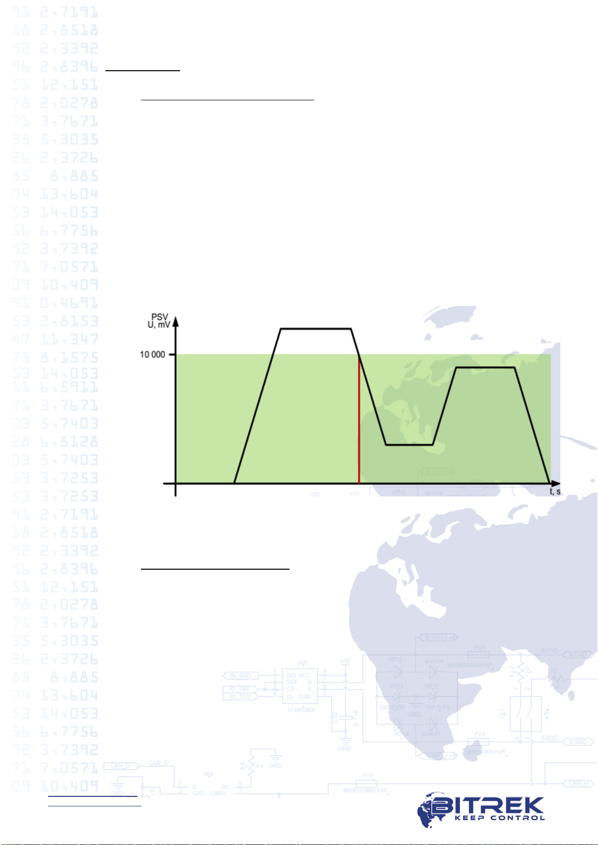
1 - Going beyond range.
An event will be generated, when actual value of sensor
readings goes beyond a configured range.
Example: Lower threshold of input voltage is set to 0 V, the
upper threshold is 10 V (10000 mV). If the input voltage
increases over 10 V, the event will be generated (Figure 5).

19
www.bitrek.com.ua
[email protected]om.ua
+380 44 507 02 07
Fig. 5. Generation of the Event by Going Beyond Range.
2 - Going within/beyond range.
An event will be generated each time when actual value of
sensor readings crosses the limits of a configured range.
Example: Lower threshold of input voltage is set to 5 V (5,000),
and the upper threshold is 10 V (10,000 mV). When actual
input voltage goes off the limits of a configured range, the
event is generated (Figure 6).
Fig. 6. Generation of the Event by Going Within/Beyond Range.
3 - Monitoring.
When this mode is selected, the data will be transmitted
continuously, and no events will be generated.
4 - Monitoring + Going Within Range.
When a Going Within Range event is generated, actual value
from the sensor starts to be transmitted to the server in the
monitoring mode.

20
www.bitrek.com.ua
[email protected]om.ua
+380 44 507 02 07
5 - Monitoring + Going Beyond Range.
When a Going Beyond Range event is generated, actual value
from the sensor starts to be transmitted to the server in the
monitoring mode.
6 - Monitoring + Going Within/Beyond Range.
When one of the events is generated, actual value from the
sensor starts to be transmitted to the server.
7 - Change of Input by a Preset Value.
When an input value changes increasingly or decreasingly by a
preset value, respective event will be generated. Value of the
setting is specified by the Upper Threshold parameter.
8 - Monitoring + Change of Input by a Preset Value.
When the events is generated, actual value from the sensor
starts to be transmitted to the server.
Parameter 5 –Averaging Constant.
It is the time during which an I/O component must be within a particular
state in order to generate an event. This setting is specified in
milliseconds (X*50 msec, i.e. when setting the value to 10, the constant
will be 10*50=500 msec).
The list of all I/O components of the device available for
configuration is given in Addendum 2.
Configuring Alarms
The device can be configured so as to make an outbound call if a
particular condition is met. Activation of a particular I/O component
constitutes such condition. Voice calls must be enabled in general
configuration settings of the device. I/O component must be enabled,
configured to one of the events (going within range, going beyond range,
going within/beyond range), its ID must be set as a trigger for outbound
calls, and an authorized phone number Phone0 must be configured.
Note
Outbound call can only be made or an SMS message can only be
sent to a phone number specified in parameter 0261 (Phone0).
Additional prerequisites include device being within the GSM carrier
coverage area and sufficient balance. In case the device is beyond the
coverage area, the call will be postponed until such time when the device
returns back to the coverage area. The device takes one attempt to make
an outbound call per each trigger activation.
Alarm configuration settings are specified in the Security section of
Addendum 1. Authorized phone number Phone0 is specified as the ID
0261 parameter.
Table of contents
Other BITREK GPS manuals

BITREK
BITREK BI-530P TREK User manual

BITREK
BITREK BI 530R TREK User manual

BITREK
BITREK BI-868 TREK HW2 User manual

BITREK
BITREK BI-520L TREK User manual

BITREK
BITREK BI-810 TREK User manual

BITREK
BITREK BI 868 TREK User manual

BITREK
BITREK BI 820 TREK OBD User manual

BITREK
BITREK BI 810 TREK User manual

BITREK
BITREK BI-910 TREK User manual

BITREK
BITREK BI-530C TREK User manual


