BJ Live BJ-EX5 MyRoom! Centre User manual
c.Mare de Déu del Coll, 70,Local|08023|Barcelona|Spain|t.+34 93 285 04 37|fax + 34 93 553 56 34| info@bjliveat.com | www.bjliveat.com
BJ-EX5 MyRoom! Centre
Assembly guide

BJ-EX5 MyRoom! Centre
Page 2
Contenido
1_Parts of the equipment ............................................................3
2_Display configuration ...............................................................6
3_Audio connections ................................................................. 10
4_Connections for the vibration.................................................. 11
5_Setting up a tablet as the control screen .................................. 14
BJ-EX5 MyRoom! Centre
Page 3
1_Parts of the equipment
1.1_ Components
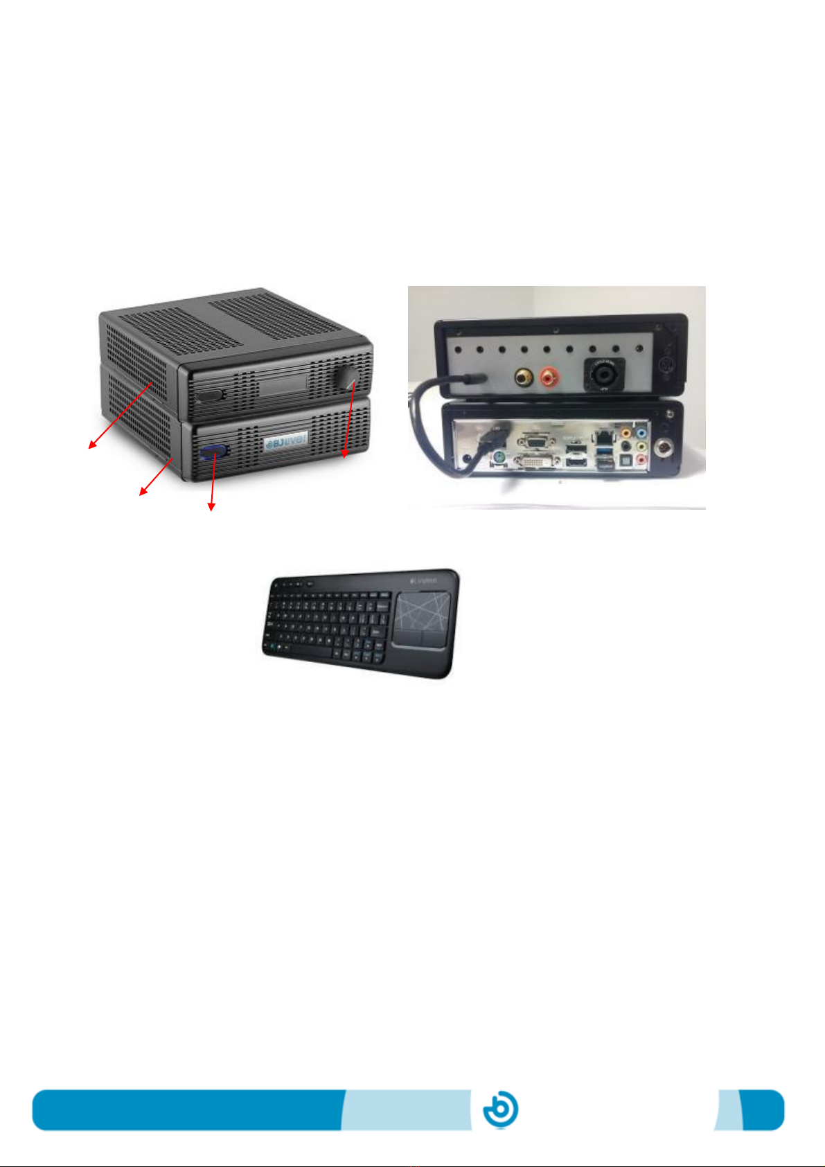
MyRoom! Centre is comprised by two different modules (see figure below) connected
to each other by means of a USB cable. The equipment includes a wireless keyboard
with a touchpad to control the pointer.
Fig. 1 –Parts of MyRoom! Centre: Front view, Rear view, Keyguard with touchpad.
Module 1 contains:
Optimized Windows Computer
Control SHX software and default contents
Switch on button
Module 2 contains:
SHX Central Device
Vibration and audio amplifier
Control of vibration intensity
Unlike the SHX Central Rack, MyRoom! Centre does not include a PC monitor. Section
2 explains how to connect and configure the displays.
Module 1
Module 2
Switch on
button
Control of
vibration
intensity

BJ-EX5 MyRoom! Centre
Page 4
The device will be shipped with the 2 modules separated and unconnected. They can
be assembled one on top of the other or side by side. Avoid placing the modules in a
position where the USB cable is forced.
Each module has its own power supply. Connect the corresponding power supply to
each module and switch on MyRoom! Centre only when all the connections to the
additional elements have been done.
1.2_ Connections of module 1
All the connections are at the rear of the module. They include the standard Windows
connections for VGA, HDMI, network, speakers, wireless keyboard, mouse, power
supply, additional USB ports (one of them is used to connect the two modules) and
DMX lighting.
Fig. 2a –Connections available in module 1 of MyRoom! Centre.
1.3_ Connections of module 2
All the connections are at the rear of the module. They include the connection for the
vibroacoustic element, sound input for vibration, 6+3 switch inputs (see table below),
and power supply. This module has the USB cable that connects the two modules.
USB cable from module 2

BJ-EX5 MyRoom! Centre
Page 5
Fig. 2b –Connections available in module 2 of MyRoom! Centre.
The following table indicates the function of each switch input:
Input 1
Triggers the action programmed in Cell 1 in the active template
Input 2
Triggers the action programmed in Cell 2 in the active template
Input 3
Triggers the action programmed in Cell 3 in the active template
Input 4
Triggers the action programmed in Cell 4 in the active template
Input 5
Triggers the action programmed in Cell 5 in the active template
Input 6
Triggers the action programmed in Cell 6 in the active template
Input 7
Allows the access via scanning. Triggers the action programmed in the selected
cell in the active template.
Input 8
Triggers the action programmed in a cell selected randomly in the active
template.
Input 9
Triggers the action programmed in a cell selected sequentially in the active
template.
USB cable to module 1

BJ-EX5 MyRoom! Centre
Page 6
2_Display configuration
MyRoom! Centre runs the SHX program, which allows playing multimedia contents
while controlling lighting, special effects, vibration and sound. This section presents
different options to configure the display of MyRoom! Centre. From now on we will
consider:
a. Control screen: the screen acting as the PC monitor. This screen could be a
monitor, TV or beamer connected via VGA to the PC in module 1.
b. Display screen: the screen where the results (video, images) are displayed.
This screen could be a TV or beamer connected via HDMI to the PC in module
1.
The control screen must be connected using the VGA port, whereas the
display screen must be connected via HDMI.
1. One screen only: the control and the display screen are in the same device, for
example a TV or a beamer. Connect the HDMI cable from MyRoom! Centre to the
HDMI input of the beamer or the TV.
When selecting the content by pressing a cell/button in the program, this will be
displayed in the same screen. To come back to the control screen when the
multimedia content finishes, slide the pointer to the upper right corner of the screen
and click on the red cross.
MyRoom!
Centre

BJ-EX5 MyRoom! Centre
Page 7
We recommend waiting until the multimedia content finishes before closing it.
However, if you need to stop the content, slide the pointer to the upper right corner
and click on the red cross.
2. Two screens in two different devices: the activities panel will be displayed in the
control screen (for example the monitor) and the results in a different device (for
example the TV or beamer).
In this case the control screen must be a standard PC monitor with Signal Input: D-
Sub. The display screen could be a TV or beamer with at least one HDMI port
available.
Connect the computer screen via VGA and the display screen via HDMI to the PC
in module 1.
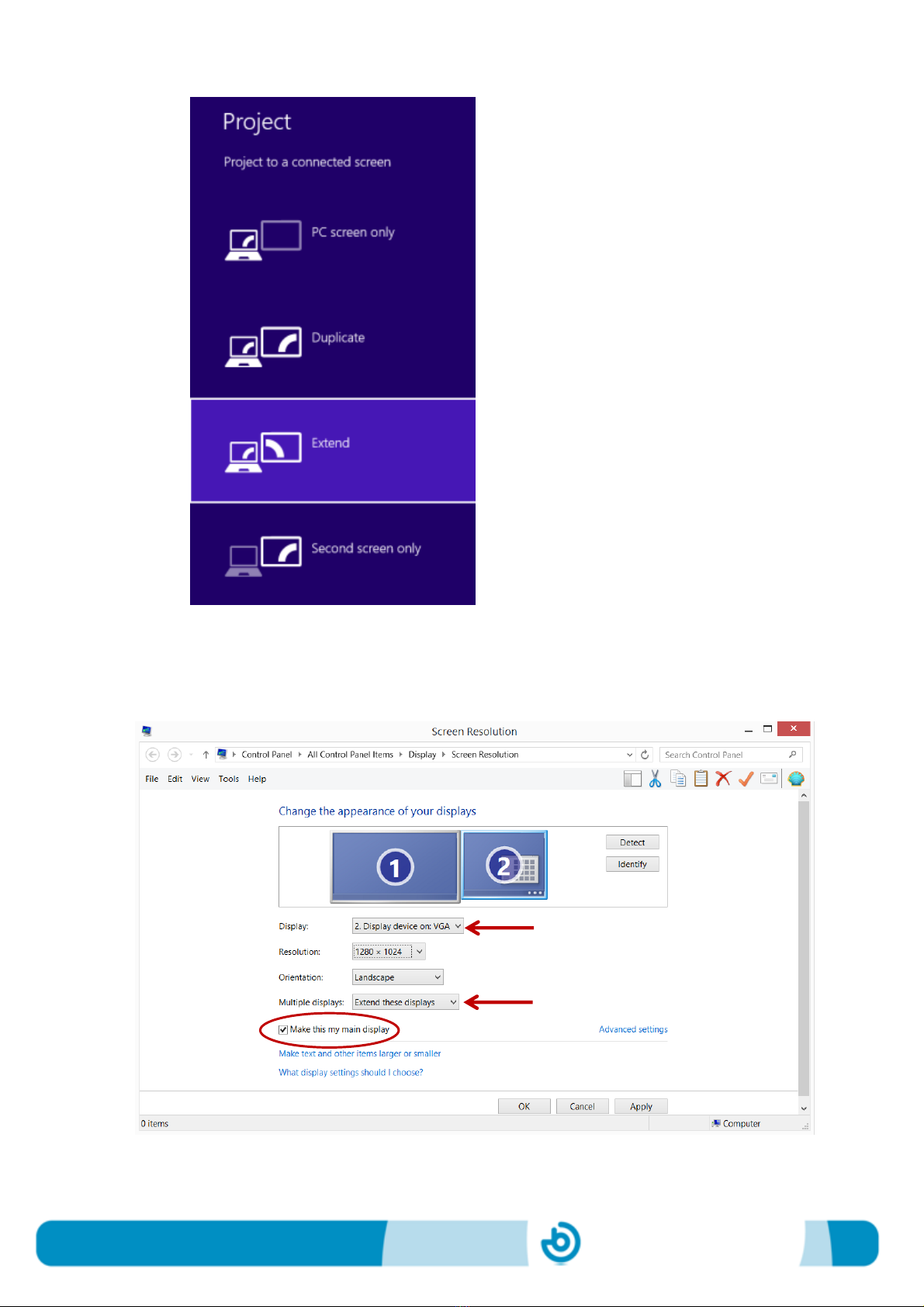
It is necessary to “Extend” the computer screen and select the computer screen as
the main screen. To extend the computer screen:
a. Press + P
b. Choose “Extend”
BJ-EX5 MyRoom! Centre
Page 8
To set the computer screen as the main screen, go to menu “Screen Resolution”:

BJ-EX5 MyRoom! Centre
Page 9
Make sure that you’re choosing the screen connected via VGA and that the multiple
displays are extended.
3. Two screens in the same device: This is the case of using a TV or beamer with
multiple inputs. In this case, the HDMI cable from MyRoom! Centre and the VGA
cable will be connected to the corresponding TV or beamer inputs.
The control screen and the display of the results will be in the same device but in
different “channels”. To access the activities panel, choose to display the VGA
channel from the TV source options. To watch the result, choose to display the
HDMI channel.
As in case 2, with this configuration is necessary to extend the multiple screens and
set as main screen the one connected via VGA.
Configurations 2 and 3 can be set up in a way that the control screen is displayed on a
tablet. In this case it will be necessary to connect the access point to the PC using a
standard Ethernet cable, and configure a WiFi connection. It is possible to use any
Android or iOS tablet with a Splashtop program installed. See section 5 of this manual
to learn how to display the control screen in a tablet.

BJ-EX5 MyRoom! Centre
Page 10
3_Audio connections
There’re two possible ways to connect the audio:
1) If the control and the display screen are connected via HDMI to the TV or to the
beamer, the sound will be played through the speakers integrated in the TV or in
the beamer. The volume can be controlled through the standard volume control
available in any of these devices.
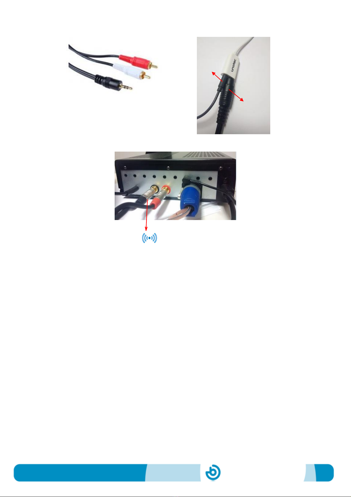
2) If you want to add an external speaker to the PC, the provided audio signal splitter
with standard jack input of 3.5mm should be connected to the audio output of the
PC:
Audio signal splitter
An audio signal splitter is necessary in order to connect also the vibration, as we will
see in the following section.
The jack connector of the external speaker should be connected to one of the jacks of
the splitter. The volume is controlled using the standard volume control of the external
speakers.
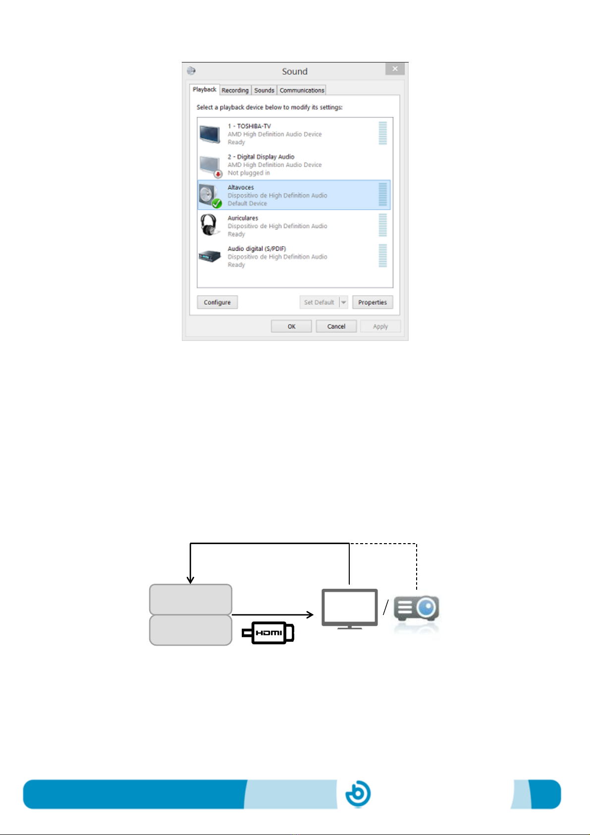
If the external speakers are connected, they should be set as default playback device
in the sound options of the PC:
BJ-EX5 MyRoom! Centre
Page 11
4_Connections for the vibration
In the SHX System, the vibration of any vibroacoustic element is generated by the
sound. There’re two possible options for generating the vibration:
1) If the PC of MyRoom! Centre is connected via HDMI to the main display (TV or
beamer), the RCA to RCA cable provided should be connected from the audio
output of the TV or projector to the audio inputs for vibration available in the module
2 of MyRoom! Centre.
MyRoom!
Centre
Audio out
Audio in for
vibration

BJ-EX5 MyRoom! Centre
Page 12
RCA to RCA Cable
Connection of RCA to audio output of a TV
Connection of RCA to audio inputs for vibration of module 2
2) If it has been added an external speaker to play the audio, it is necessary to use
the audio splitter (as indicated in the former section) and the RCA-jack cable
provided.
MyRoom!
Centre
Audio in for
vibration
Audio out
BJ-EX5 MyRoom! Centre
Page 13
RCA to jack cable
Connection of jack to audio splitter
Connection of RCA to audio inputs for vibration of module 2
Vibration
To external
speakers

BJ-EX5 MyRoom! Centre
Page 14
5_Setting up a tablet as the control screen
In those cases where the control and the display screen are shown in different devices
or in different “channels” (for example in a TV), the control screen can be displayed on
an additional device, like a tablet.
For doing so, follow these steps:
1. Connect the access point provided to the PC in module 1 using a standard Ethernet
cable. Switch it on.
2. A specific wireless network has been configured by the manufacturer. The
manufacturer will provide the information about the Network ID and password in
each case.
3. Connect your tablet to the Internet and download the App Splashtop.
If you’re using an Android tablet, download the app from this link:
https://play.google.com/store/apps/details?id=com.splashtop.remote.pad.v2
If you’re using an iPad/iPhone, download the app from:
https://itunes.apple.com/app/id382509315
https://itunes.apple.com/app/id561386772
4. Install the App in your tablet.
5. Look for the specific wireless network in the tablet and click on connect.
6. Open the Splashtop App installed in the tablet and introduce the user account and
the security code provided.
7. Select the wireless network that appears in Splashtop desktop.
BJ-EX5 MyRoom! Centre
Page 15
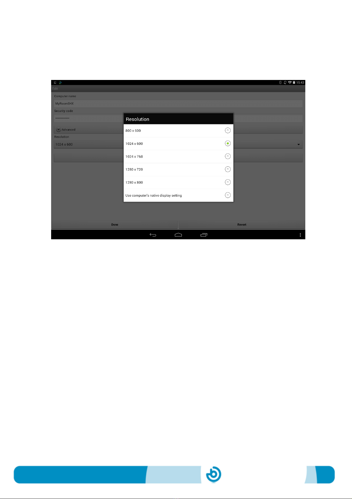
In some occasions it will be necessary to change the screen resolution of your tablet.
For doing so, click on the arrow at the right edge and choose the right screen
resolution, as in the example below:
Open the SHX program to ensure that you have chosen the right screen resolution for
your tablet.
After adjusting the screen resolution, the tablet should show the same contents as the
control screen.
From now on, the tablet will be your control screen to select activities, etc.
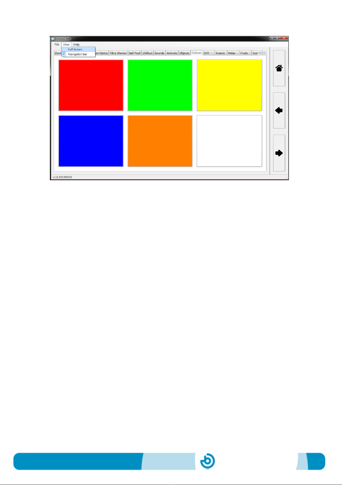
To enlarge the SHX program window, use the “Full view” functionality available:
BJ-EX5 MyRoom! Centre
Page 16
To come back to the standard view and be able to see the SHX menu, place the
pointer over the upper frame of the SHX program’s window and press the key “Alt” in
your keyboard.

Table of contents


