Because the safety instruction is for preventing the accident or danger by using the product safely and correctly, please
keep the instructions invariably. We cannot be held responsible for what happens to our products when you did not keep
this users manual.
Safety Instruction
Warning Death, serious injury damage may result when following instructions are not observed
To dry this unit, do not use heat machines
(stove, microwave).
Fail to do may result in explosion or mal-function.
Do not disassemble or shock
No goods damaged by doing so will be accepted for free
service or replacement.
To clean the unit, do not use chemicals
(benzene, alcohol, thinner)
Fail to do may result in fire.
Do not look into IR sensor while using the remote
controller.
Fail to do may result in eye problems.
Caution injury or property damage may result when following instructions are not observed
Install the product according to the
manual
Fail to do may result in mal-function.
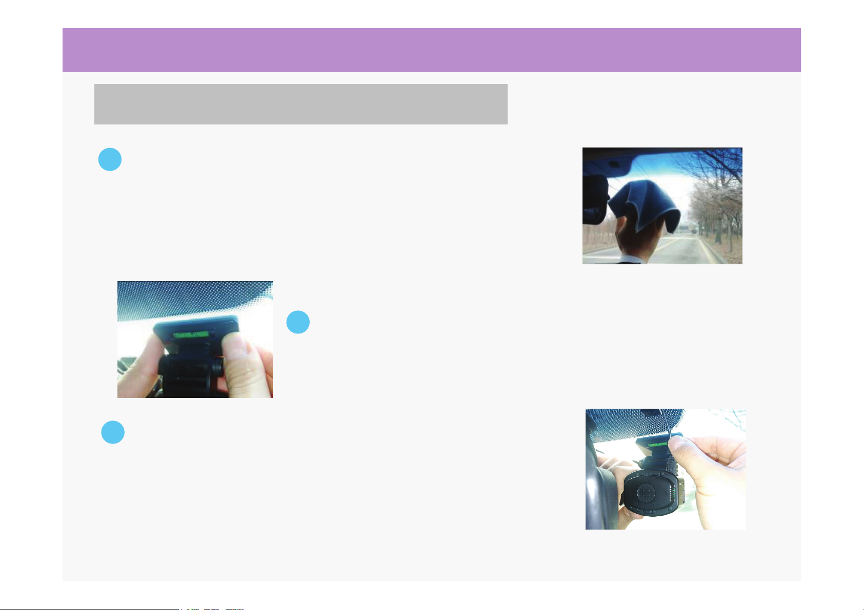
Keep the windshield clean especially front area of
lens
The system may not operate properly when objects or
debris block the camera lens of there is a reflection.
Tape the unit stably using both face tape.
Fail to do may result in decreasing performance of
system due to movement of unit by vibration of vehicle.
Do not place any objects on dash board
The system will not operate normally/regularly when
other items on dashboard reflects off the glass and
interferes with device. Minimize display viewing while driving
Viewing the display may distract the driver from looking
ahead of the vehicle and cause an accident.