Black Diamond Equipment TC1024DCA User manual

TC1024DCA
Tire Changer

Content
●IMPORTANT SAFETY INSTRUCTIONS .....................................3
●OWNER’S RESPONSIBILITY ........................................................4
●OPERATOR PROTECTIVE EQUIPMENT....................................4
●NAME OF MAIN PARTS .....................................................................5-6
●INSTALLATION .....................................................................................7-11
●OPERATION INSTRUCTION................................. 12–16
●A) Demounting ............................................... 12-14
●B) Mounting .................................................. 15-16
●INFLATION .................................................... 17
●MAINTENANCE TIPS ........................................ 18
●Diagram ....................................................... 19

(1) IMPORTANT SAFETY INSTRUCTIONS
1. Eye and face protection recommendations:
“Protective eye and face equipment is required to be used where there is a reasonable probability
of injury that can be prevented by safety glasses, or a face shield must be pro-vided by the owner
and worn by the operator of the equipment. Care should be taken to see that all eye and face
safety precautions are followed by the operator. ALWAYS WEAR SAFETY GLASSES. Everyday
glasses only have impact resistance, they are not safety glasses.
2. Do not disable hood safety interlock system, or in any way shortcut safety controls and opera-
tions.
3. Be sure that wheels are mounted properly, the hub nut engages the arbor for not less than four
(4)
turns, and the hub nut is firmly tightened before spinning the wheel.
4. Read and understand this manual before operating. Abuse and misuse will shorten the func-
tional life.
5. Be sure the balancer is properly connected to the power supply and electrically grounded.
6. Do not operate equipment with a damaged cord or if the equipment has been dropped or dam-
aged until it has been examined and repaired by a qualified serviceman.
7. Do not let cord hang over edge of table, bench, or counter or come in contact with hot mani-
folds or moving fan blades.
8. If an extension cord is necessary, a cord with a current rating equal to or more than that of the
equipment should be used. Cords rated for less current than the equipment may overheat. Care
should be taken to arrange the cord so that it will not be tripped over or pulled.
9. Keep guards and safety features in place and in working order.
10. Wear proper clothing. Safety toe, non-slip footwear and protective hair covering to contain hair
is recommended. Do not wear jewelry, loose clothing, neckties, or gloves when operating the bal-
ancer.
11. Keep work area clean and well lighted. Cluttered and/or dark areas invite accidents.
12. Avoid dangerous environments. Do not use power tools or electrical equipment in damp or wet
locations, or expose them to rain.
13. Avoid unintentional starting. Be sure the machine turned off and power disconnected before
servicing.
14. Disconnect the balancer before servicing.
15. Use only manufacturer’s recommended accessories. Improper accessories may result in per-
sonal injury or property damage.
16. Repair or replace any part that is damaged or worn and that may cause unsafe balancer op-
eration. Do not operate damaged equipment until it has been examined by a qualified service
technician.
17 Do not allow untrained persons to operate machinery.
18. To reduce the risk of fire, do not operate equipment in the vicinity of open containers or flam-
mable liquids (gasoline).
19. Adequate ventilation should be provided when working on or operating internal combustion
engines.
20. Keep hair, loose clothing, fingers, and all parts of body away from moving parts.
21. Use equipment only as described in this manual.
22. Use only manufacturer’s recommended attachments and accessories.
The risk level used in this manual agrees with the following definitions and logos.
Danger
Look at this symbol
It means: direct danger, which will lead to serious personal injury or death.
Warning
Look at this symbol
It means dangerous or unsafe behavior, which may lead to serious personal injury or death
Pay attention to
Look at this symbol
It means: dangerous or unsafe practices, which may lead to minor personal injury or loss of
products or property.
Look at this symbol
Keep alert! It involves your safety or the safety of others.
(2)OWNER’S RESPONSIBILITY
1. To maintain machine and user safety, the responsibility of the owner is to read and follow these instructions:
2. Follow all installation instructions.
3. Carefully check the unit for correct initial function.
4. Read and follow the safety instructions. Keep them readily available for machine operators.
5.Make certain all operators are properly trained know how to safely and correctly operate the unit,
and are properly supervised.
6. Allow unit operation only with all parts in place and operating safely.
7.Carefully inspect the unit on a regular basis and perform all maintenance as required.
8.Service and maintain the unit only with authorized or approved replacement parts.
9.Keep all instructions permanently with the unit and all decals/labels/notices on the unit clean and visible.
10.Do not override safety features.
(3) OPERATOR PROTECTIVE EQUIPMENT
Personal protective equipment helps make tire servIcing safer. However, equip-
ment does not take the place of safe operating practices. Always wear durable
work clothing during tire service activity. Loose fitting clothing should be
avoided. Tight fitting leather gloves are recommended to protect operator’s
hands when handling worn tires and wheels. Sturdy leather work shoes with
steel toes and oil resistant soles should be used by tire service personnel to
help prevent injury in typical shop activities. Eye protection is essential durng
tire service activity. Safety glasses with side shields, goggles, or face shields
are acceptable. Back belts provide support during lifting activities and are also
helpful in providing operator protection. Consideration should also be given to
the use of hearing protection if tire service activity is performed in an enclosed
area, or if noise levels are high.
WARNINGS
Inflation Gun
( No applicable on
IT)
Lever Lever Protector Mounting Head Pro-
tector (MHPP)
Mounting Head Pro-
tector (MHPP)
Manual Long Plastic Jaw
Protector
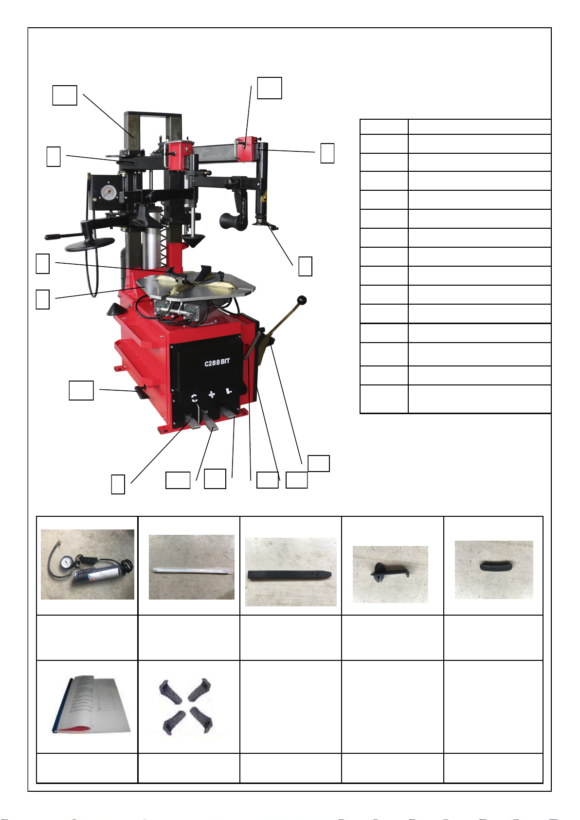
STANDARD ACCESORIES
(4) NAME OF MAIN PARTS
1 Bead Break Pedal
2 Clamping Pedal (Open)
3 Clamping Pedal (Close)
4 Rotation Pedal
5 Turntable
6 Jaw
7 Mounting Head
8 Swing Arm
9 Dual Assist Arm
10 Control Valve ( Column)
11 Column Assembly
12 Bead Breaker
13 Bead Breaker Pad
14 Lever
15 Inflation Pedal
2-3
4
5
67
8
9
10
11
12
13
114
15
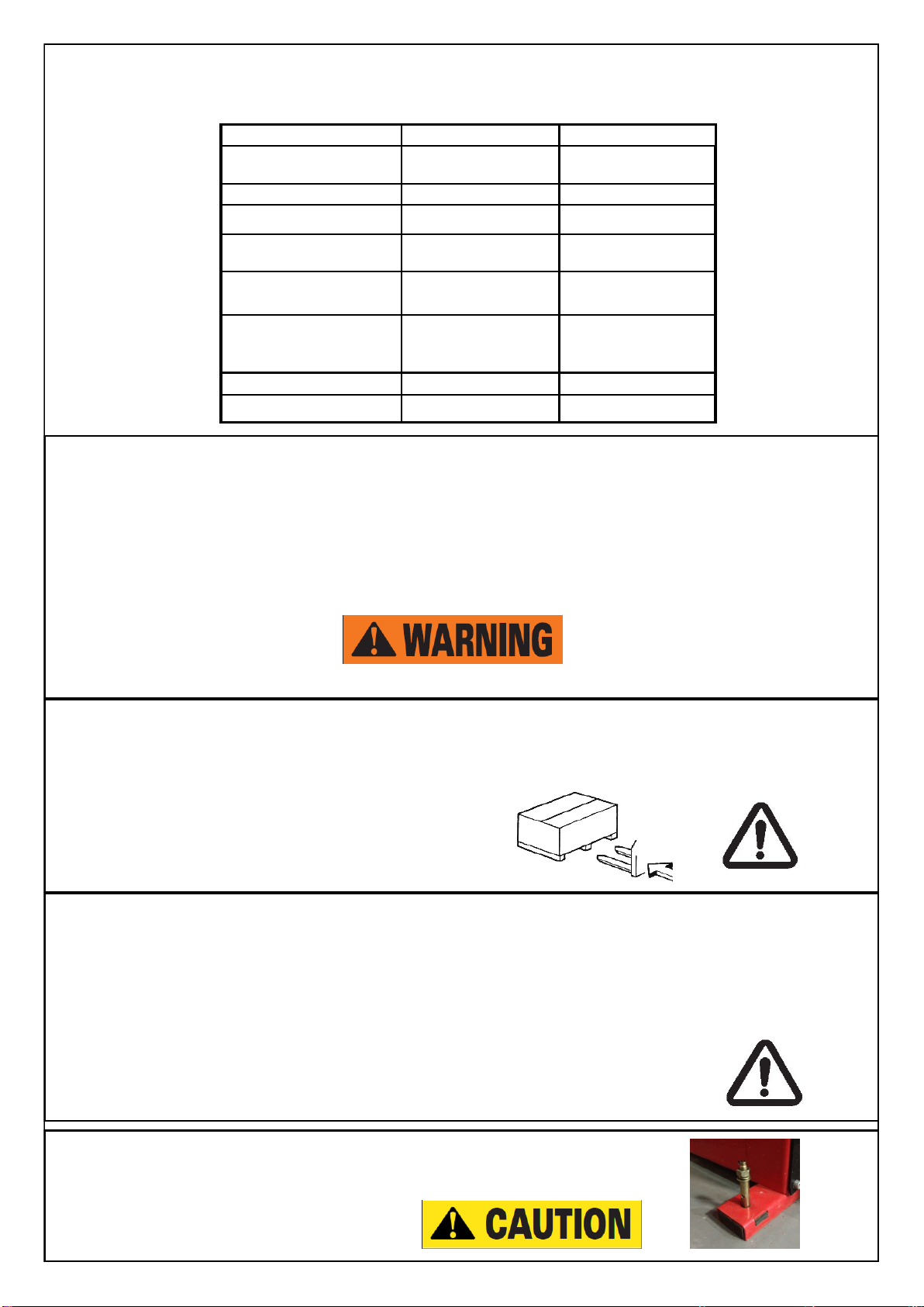
(7) TRANSPORTATION
The machine must be sent with original packing the machine must be packaged with the corresponding ton-
nage Forklift loading and unloading,
the truck according to FIG position insert foot. (Figure 1)
。
(6) OPERATION SETTING
●Pressure setting: the machine to work properly due within 7-10bar pressure range, so coherent
supply pressure should reach 7bar above.
●Fuel settings: lubricator oil and fuel is calibrated at the factory , if the fuel goes in too fast or too
slow, use a screwdriver to adjust the oil mist on the needle, and then step on the foot pedal
pressure tire 5 to 10 times .If the lubricator drops a drop of oil , it meets the requirement. Re-
member to regularly refil 32 # hydraulic oil to the oil cup (2/3 cup)
(8) UNPACKING THE MACHINE
After removing the packaging, the machine and its components visually visible damage check, if in doubt
please contact your dealer. Package materials such as plastics, polystyrene, nails, screws, wood,
cartons and other waste must be placed in a box, according to local regulations. Please check the box that
comes consistent with the packing list when unpacking.
Note: When disassembling the machine must wear gloves to avoid
contact with the packaging material and scratch or galling.
Before Usage
We strongly suggest installing on the ground to ensure the performance of
the machines
Outside clamping 10”~22” 10”~24”
Inside clamping 12”~24” 12”~26”
Max. wheel width 14” 14”
Max. wheel diameter 960mm 1080mm
Working air pressure 8~10bar 8~10bar
Bead breaker force (at
8bar)
2500kgf 2500kgf
Motor speed /
Operating speed
1 speed / 6r.p.m
1 speed / 6r.p.m
Shipping weight 350kg 350kg
Motor power 0.75~1.1kw 0.75~1.1kw
(5) SPECIFICATION

(9) INSTALLATION
Positioning and installation
●The machine has been placed in selected positions, marked expansion screws, tighten the mounting
steadily.
●All electrical installation must be performed by qualified person.
●Before installation and connection, check if the power voltage of the machine on the nameplate
matches the labe, which also cable with a protective grid must be installed and there is a good
ground cover protection and automatically install air leakage switch on the main power source, Drain
power set at within 50mA / s .
●Check the motor rotation direction (this check only for machines equipped with three-phase motors).
●Depress the turntable forward / reverse control pedal wheel should rotate clockwise, counterclock-
wise rotary dial, you can swap any two at the switch
●Phase cable connector, if user does not follow the above instruction, ,factory will not be responsible
to any damage caused by above instructions.
Note: If the machine does not have the power plug, the user must install a self-consistent voltage and
machine power plug.
●·The machine requires air pressure with range 7-10 bar (100-140 psi) to meet the guaranteed use of
the machine, if less than 7bar (100psi),bead breaker shovel may not be working as usual.
●Must use blow piper before air hose newly installed in order to avoid damage from the new pipe to
the machine. Users has to regularly drain he air compressor.
●Connect the air compressor and filter system on the machine. After the connection , user should
check on the lubricator pressure gauge whether the requirements in the pressure setting is met, if not
please check the tubing or air compressor if it is defective.

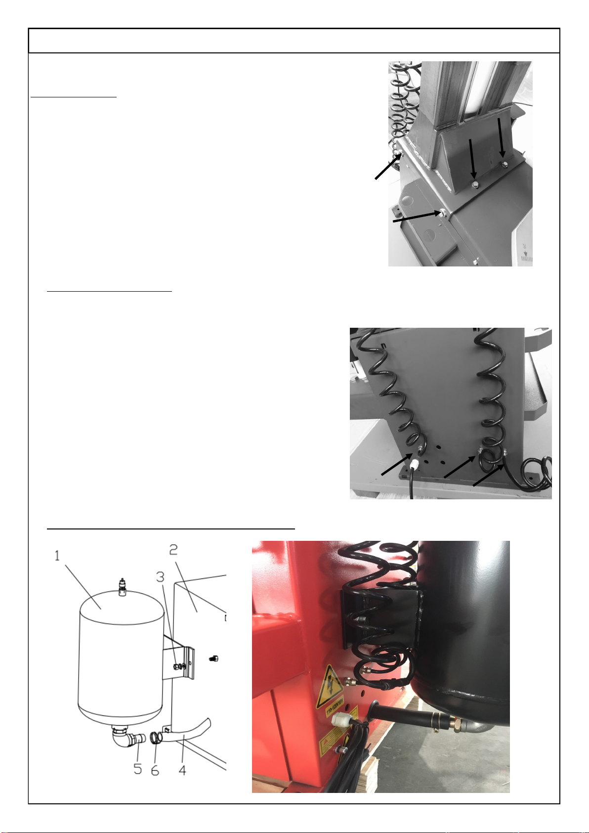
Column Installation
1)Bring the column from other package .
2)Install 8 bolts on the cabinets. ( Bolts was installed on the cabinet)
Inflation gun & IT Installation
Follow below instruction :
1) Step pedal 2 times and ensure the clamping will be
opened.
2) If you need to install inflation gun, connect this. ( No IT system)
3) Connect the nut with 7-8mm hose.
4) For IT version, you have to connect the air tank at the back of
the cabinet.
A) You install Air tank bolts (No.3) with bolts
B) Connect No.4 , 5 and 6. Make sure No. 6 Ring is tight.
Installation should be done as the picture below
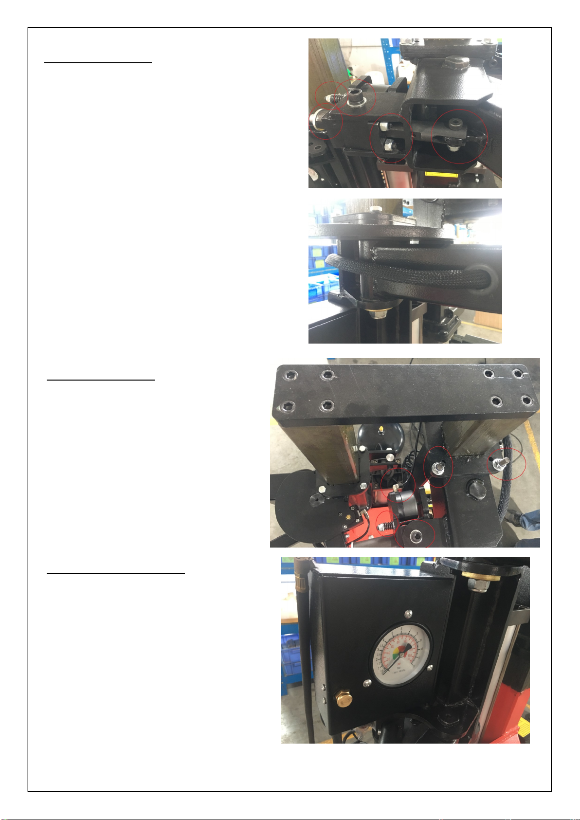
Swing Arm Installation
Install the bolts and nuts according to the picture.
This is the air lock swing arm system. Please check
the air lock after installation and before operation.
Air hose connection should be go through the swing
arm to the control valve.
Assist Arm Installation
Make sure the connection and nuts are well con-
nected.
Install Air Gauge ( IT version)
Connect the hose to the back of the cabinet.
Ensure the air gauge is functional and stable during
The control of the assist arm column.
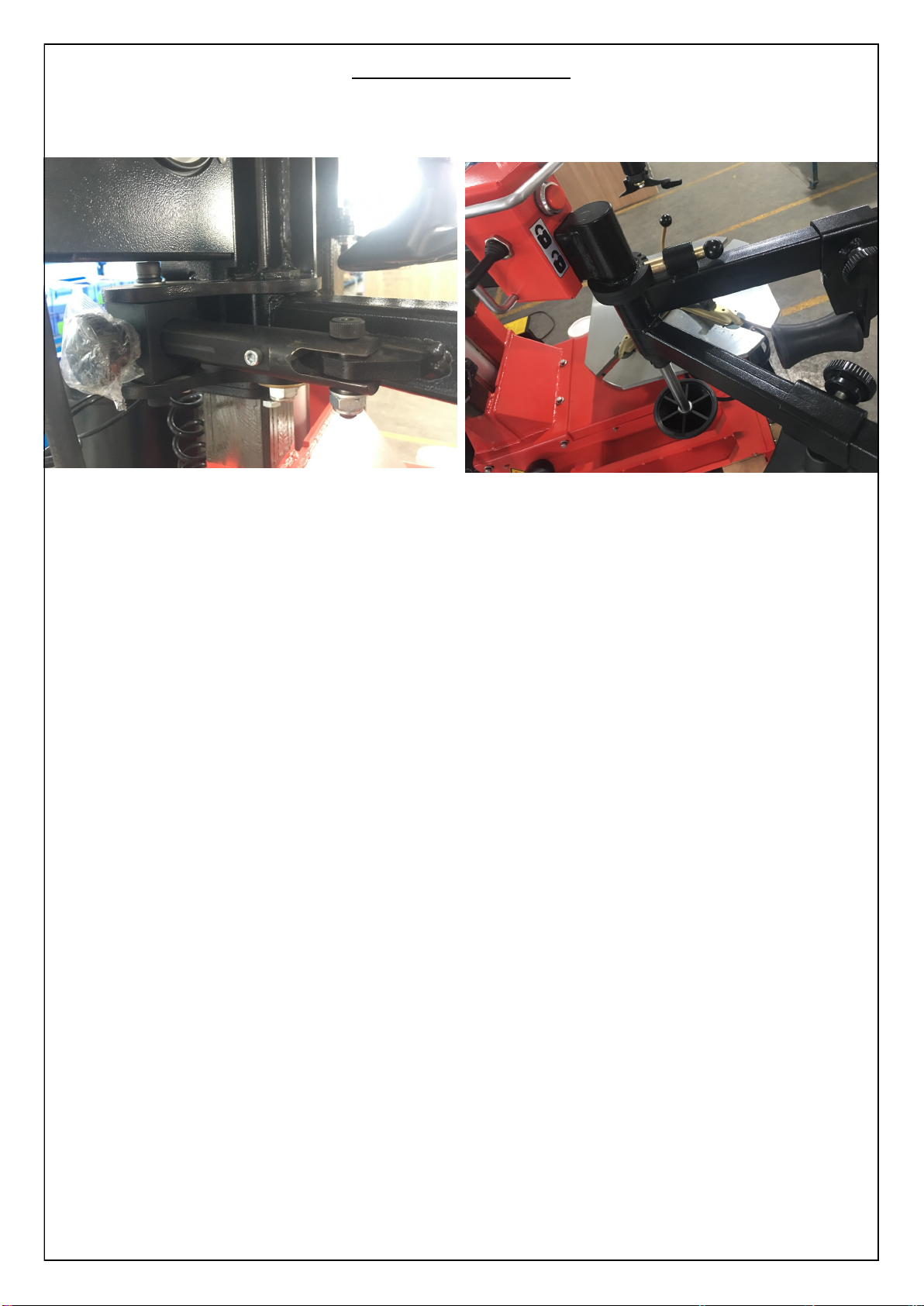
Installation of assist arm
Follow the picture to connect the nut and screw,

(10) OPERATION INSTRUCTION
This unit must be properly operated and properly maintained to help avoid accidents that could injure
the operator or bystanders, or damage the unit. This section of the Operating Instructions manual review
basic operations and use of controls. These instructions should be reviewed with all employees before they are
allowed to work with the machine. Keep these instructions near the machine for easy reference.
This machine may operate differently from machines you have previously operated.
Practice with a regular steel wheel and tire combination to familiarize yourself with the machine’s operation and
function.
A. Remember to remove all weights from both sides of the wheel. Weights left on backside of wheel may
cause the wheel to be clamped unleveled. This may result in the combination mount/demount tool contacting
the rim causing scratches. On alloy wheels, always rotate the wheel one turn after setting the Duckhead
mount/demount tool to insure proper wheel clamping.
B. Always review with the owner any nicks and scratches on expensive wheel and tire combinations
prior to servicing.
C. Review the performance wheel section of this manual prior to servicing performance tire/wheel com-
binations.
Change a new tire
Loosening the beads on a partially or fully inflated tire is unsafe and
causes excess movement and friction against the bumper pads and excessive
wear on pivots. Deflate the tire completely to prolong the life of your ma-
chine.
1. Deflate the tire completely by removing the valve core from the valve
stem (figure 1). Be cautious and do not smoke as a flammable gas
could have been introduced into the tire at some time.
Tires are always installed and removed from the rim’s narrow
side.
D. Always loosen the bead on the narrow side
of the wheel’s drop center first (tire removed in figure 2 for clar-
ity).
E. The clamps on the table top may extend beyond
the table top itself. To avoid damaging the clamps, move them
to their full inward position before positioning a tire for bead
loosening.
F. Use extra care in positioning the bead loosened
shoe on larger wheels/tires, and on alloy wheels.
Make sure the shoe rests next to but not on the
rim, and not on the tire sidewall.
2. Actuate valve (or pull) to position the bead loosener.shoe away
from the machine and roll wheel into position. The valve stem should be
in the 2 o’clock position to accommodate a possible asymmetric
safety hump type rim. Position the bead loosener shoe against the
tire next to, but not on, the rim. Actuate the bead loosener handle/button
to position the shoe or press the bead loosener pedal to position the
shoe and loosen the bead. It may be necessary to loosen the
bead in multiple locations around the tire (figure 3).
G. It will be easier to outside clamp the wheel to the
table top if the long side of the rim is loosened last.
4. Apply tire manufacturer’s approved rubber lubricant
liberally to entire circumference of both tire beads after
loosening (figure 5).
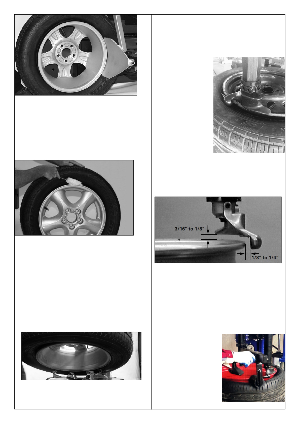
5. Determine the mounting side of the wheel. The mounting
side is the narrow side of the drop center. See figure 2 for
more information on the drop center.
6. Place tire/wheel assembly on table top with mounting
side up (figure 6). Use the clamp control pedal to move the
clamps inward (push pedal down) or outward (toggle pedal
up). Clamp steel wheels from the inside (clamps push out-
ward against wheel). Clamp mag and custom wheels from
the outside (clamps push inward against the outside rim
edge). Refer to the Custom and Special Wheels section.
7. Move the swing arm into position. Control the valve down
on the top of the vertical slide to move the demount head into
contact with the rim edge. Push the locking button and lock
the slide arm into place (figure 7).
Figure 7 - Position
Mount/Demount
Tool
8. The mount/demount head should be in contact with the rim
edge. Turn the swing arm adjusting knob to move the mount
demount head away from the rim 1/8 to 1/4 inch (figure 8).
9. Check metal head positioning. Mount/demount metal
head should be positioned with 3/16 to 1/8 inch clearance
between the top of the rim edge and the bottom of the head,
and 1/8 to 1/4 inch clearance between the rim edge and the
head roller. If the tire is hard and stiff, you have to pull the
assist arm and control the arm pressing again the tire bead.
Once you pull the assist arm to the center position, it will be
locked automatically. Then control the arm down to press
the bead until you have certain space to put the lever into
the tire bead. (figure 9).
Figure 5 - Apply Rubber Lubricant to Tire Beads
Figure 6 - Place Tire/Wheel Assembly on Table top
Figure 8- Proper (Metal) Mount/Demount Head Position
(Figure 9). Assist arm to
help pressing the bead

H. The tool clearance may change with machine use and
should be inspected often. Failure to maintain the proper
clearance may result in damage to the wheel rim and/or tire.
J. Normal table top rotation for demounting is clockwise.
Depress the table top pedal to rotate this direction. To rotate
the table top counterclockwise, lift the pedal up with your toe.
K. Table top rotation can be stopped at any time by re-
moving your foot from the rotation pedal.
At times during the mounting and demounting proce-
dure, the bead lifting tool may encounter resistance and can
be
thrown. Keep one hand firmly on the tool to avoid possible
tool disconnect. Use the reversing feature to back out of jam-
ups. A thrown tool can cause injury.
10. Insert the smooth curved end of the bead lifting tool over
the forward end of the demount head and below the top bead of
the tire. Lift the bead up and over the knob on the Mounting
head (figure 10). Also, note the valve stem position to the
Mounting head. Use your free hand to press down on the tire
opposite the Mounting head to allow the bead to utilize the
drop center area of the rim, this position reduces stresses in
the bead and allows an easier bead lift.
Figure 10 - Insert Bead Lifting Tool
11. Push the bead lifting tool down towards the wheel to lift the
tire bead up and over the knob portion of the demount head.
Hold the tool and bead in this position (figure 11).
Figure 11 - Lift Bead Over Demount Head
12. Depress the table top pedal to rotate the wheel. The
Mounting head will guide the tire bead up and over the edge
of the wheel. Continue rotation until the upper bead is de-
mounted.
L. Push down on the tire across from the demount
head during table top rotation to utilize the drop center
area of the wheel. This reduces the tensional force on the
top or first
bead during demount (figure 10).
Figure 12 - Demounting Lower Bead
13. Lift and hold the tire at an angle so that the lower bead
is resting in the drop center directly across from the de-
mount head, and is loose below the demount head (figure
12). Insert the smooth curved end of the bead lifting tool
down over the forward end of the mount/demount tool and
below the lower bead. Lift the bead up and over the knob
on the demount head (figure 13).
Figure 13 - Guide Lower Bead Over Tool Head
14. Depress the table top pedal to rotate the wheel. The
demount head will guide the bead up and over the edge of
the wheel. Continue rotation until lower bead is de-
mounted.
M. With tube-type tires, demount the upper bead and
remove the tube before demounting the lower bead.
Mounting
This information must be read and followed carefully to
prevent accidents and injuries during mounting.
Attempts to force a bead seat on mismatched tires and
wheels can cause the tire to violently explode, causing seri-
ous personal injury or death to operator and/or
bystanders.
Check tire and wheel carefully before mounting. Make sure
the tire bead diameter and wheel diameter match exactly.
Consult the Tire Guide and/or Rubber Manufacturer's
Association for approved rim widths for tire sizes.
Never mount a damaged tire. Never mount a tire on a rusty
or damaged wheel. Damaged tires and/or wheels may ex-
plode.
When in doubt do not mount
Never mount a tire and wheel handed to you by anyone
without checking both tire and wheel for damage and to be
certain the sizes match. Do not let untrained persons
operate tire changer and keep bystanders out of service
area.
Forcing the tire onto the rim can cause bead damage. If
you damage the tire bead during mounting, STOP!,
remove tire and mark it as damaged. Do not mount a
damaged tire.
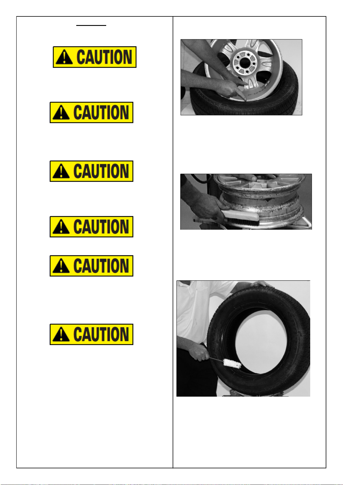
1. Before any mounting, inspect tire for damage and
verify size match between tire and wheel (fig. 14).
Figure 14 - Verify Size Match Between Tire and Wheel
2. Inspect wheel closely for damage. Clean the
wheel and remove any light corrosion or rubber residue
(figure 15). Do not attempt to service a heavily corroded
wheel, damaged wheel, or bent wheel.
Figure 15 - Inspect and Clean the Wheel
3. Inspect valve stem and replace if necessary. Next
lubricate tire beads liberally with tire manufacturer’s
approved rubber lubricant (figure 16).
Figure 16 - Lubricate Tire Beads Liberally

Q. To facilitate the mounting process, you can use the assist
arm to mount the tire quickly.
First, you adjust the nut ( D) to fit the tire diameter. 3 adjust-
ments are applied to 14”-26” wheel. From left side to right,
position 1 is for wheel 22”-26”, position 2 is for wheel 18”-
22” and position 3 is for wheel 14”-18”
Second, adjust the handle ( C )against the tire bead.
Third, use control valve to adjust the height. Make sure the A
and B is below the mounting head.
4. Place tire over wheel and move swing arm into position
making sure the valve stem is at the 9 o’clock position in
front of bead lock. Position tire so that lower bead is above
the rear extension of the mount/demount tool and below the
front knob (figure 17).
Figure 17 - Position Tire Against (Mount/Demount Tool)
5. Depress table top pedal and rotate wheel to mount lower
bead. Use drop center of wheel by forcing down on tire just
ahead of the mounting tool, and follow as tire rotates. Rotate
table top until lower bead is mounted.
6. For top bead installation, rotate the table top until the valve
stem is directly across from the mount head. Lift the upper
bead up and over the rear of the mount head. With your left
hand press down on the tire between the mount head and the
valve stem to hold the tire in the drop center. Depress table top
pedal and rotate tire until bead is mounted. Be careful to en-
sure bead stays in the rim drop center in the area ahead of
Mounting head (figure 18).
Figure 18 - Mounting Top Bead
N. If table top rotation stalls, reverse the table top mo-
mentarily until tire bead is again loose on the wheel. Reposi-
tion tire on Mounting head, make sure bead is correctly posi-
tioned in drop center of the wheel; then attempt mounting
again.
P. For low profile or stiff sidewall tires, it may be ad-
vantageous to use the bead lifting tool to initially hold the
upper bead down in the drop center.
R. For tube type tires, mount lower bead first, move
swing arm out, install tube, and then mount upper bead.
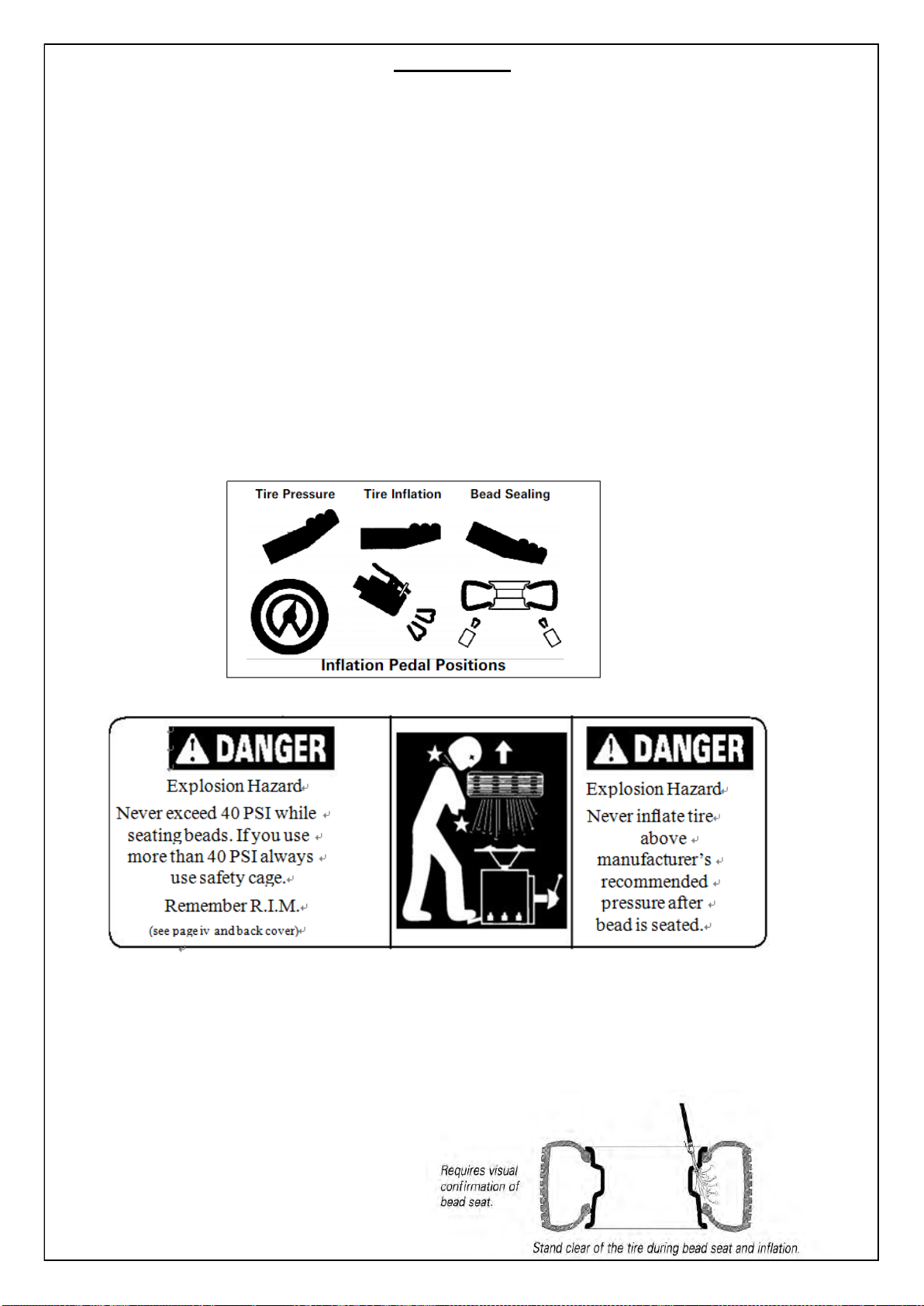
(11) Inflation
Tire inflation is performed in three steps: BEAD SEAL, BEAD SEAT, and INFLATION. These steps are explained in detail on
page 12. Read the explanation of each step and understand them thoroughly before proceeding.
The inflation pedal, located at the rear of the left side of the machine, controls the flow of air through the inflation hose, and
has three positions. Note: The clip-on chuck on the end of the hose should always be an open/freeflow style with all parts in
proper working order.
Position 1 - Tire Pressure –With the inflation hose
attached to the tire valve and the pedal in this position, the air gauge will register the air pressure in the tire. Whenever your
foot is removed from the pedal, it will return to this position.
Position 2 - Tire Inflation –This is the first activated position. With the inflation hose attached to the tire valve and the
pedal in this position, line pressure is allowed to flow through the valve system and into the tire for inflation. Correct tire
pressure is not indicated on the gauge in this position.
Position 3 - Bead Sealing –This is the second and last activated position. With the inflation hose attached to the tire
valve and the pedal in this position, line pressure is allowed to flow through the valve and to the airflate bead seal jets on the
table top for bead sealing.
1. If the rim has been clamped from the outside for
tire mounting, release the clamps, lift the tire, and move the clamps to the center of the table top.
Note the Inflation Pedal Positions (See Diagram)
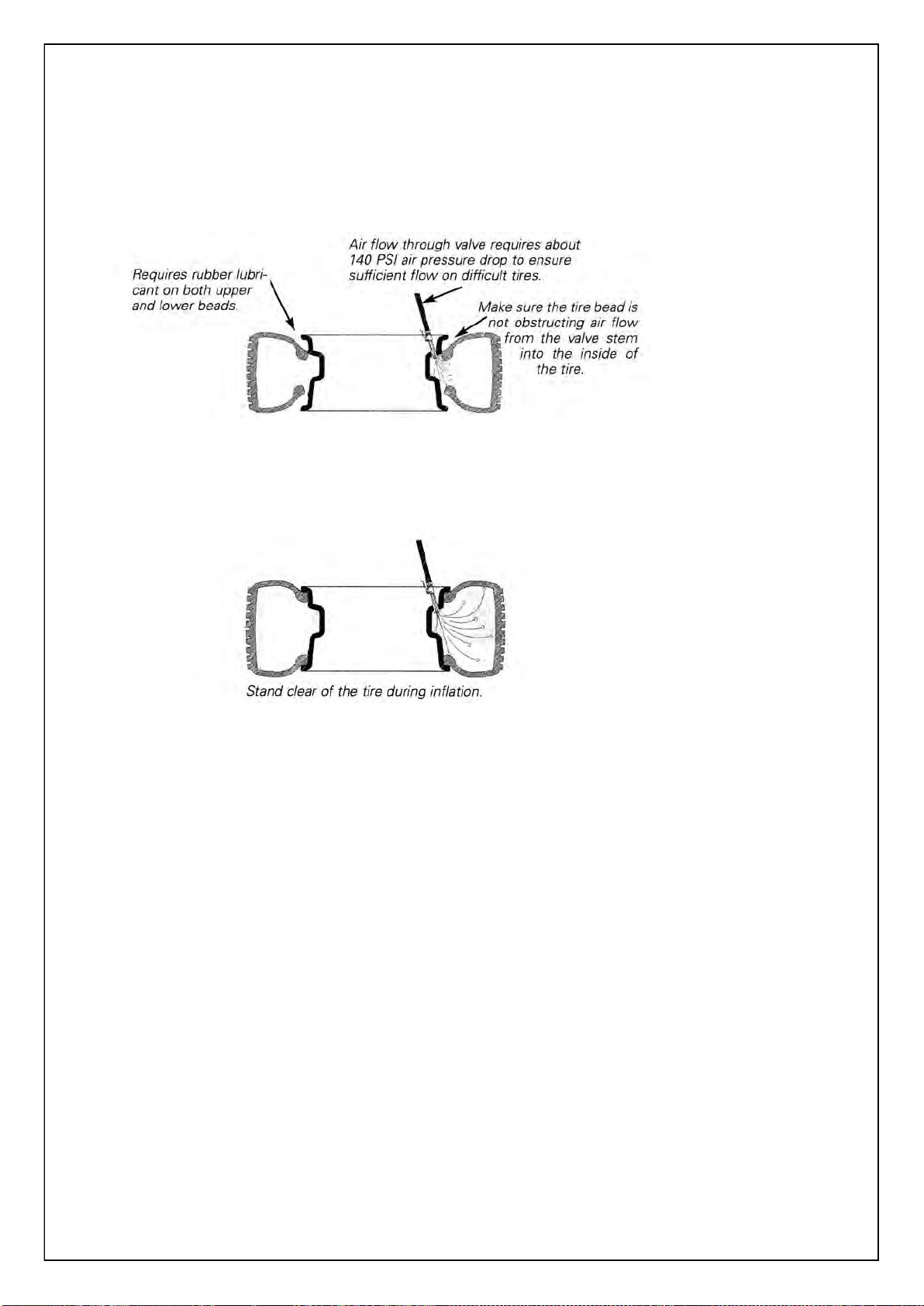
Stages of Inflation on a Conventional Tire and Rim
Review these descriptions and diagrams carefully. Refer to them as necessary during bead sealing,
bead seating, and inflation to verify that you are proceeding properly and safely.
Bead Sealing
Bead sealing is the process of capturing air pressure between the tire and the rim. The tire will
usually contain about 1/2 to 2 PSI at initial bead seal.
Bead Seating
Bead seating usually occurs on the long tapered side of the wheel first and the shorter side last.
Bead seating will usually require at least 7 PSI in the tire. 40 PSI is the maximum safe pressure at this stage
regardless of tire operating pressure. For tires requiring more than 40 PSI to bead seat use safety cage.
Most European import cars and many aftermarket alloy wheels are very tight and can be difficult to
bead seat. Also note that asymmetrical hump and run-flat tires are extremely difficult to bead seat. Follow
tire manufacturer’s recommended procedure for bead seating.
Inflation
After the beads are seated, the tire is ready to be inflated. Do not inflate the tire above the
manufacturer’s recommended pressure as stamped on the tire sidewall. The typical inflation pressure
for automobile tires is between 24 and 45 PSI. Light truck inflation pressure typically covers a wider range.
(12) MAINTENANCE TIPS
●Regular clean condensate oil and water separator cup inside.
●Regular clean operation panel lock lever and quick nut, and drip an appropriate amount of lubricating oil.
●Regularly check and tighten all bolts connecting member.
●Keep the hexagonal rod dry and clean (clean diesel) and use appropriate amount of lubricating oil drip.
●Check the drive belt tension, when you need to adjust the adjustment screw to adjust in order to achieve
the role of the drive belt tension.
●Keep a clean machine and work area to prevent dust from entering the movable member.
●Van opposite produce joint surface and an opposite surface friction combined with displacement, weekly
use of lithium-based lipid oil to lubricate.
●Regularly clean the control valve and the silencer on the valve so that it will not affect the cylinder work-
ing properly. Unscrew the muffler should be cleaned with water or cleaning with compressed air to blow
dirt.
●After each tire and the tire should be removed to clean the operation panel and debris on the box in or-
der to avoid debris during use due to excessive lead operation panel wear.
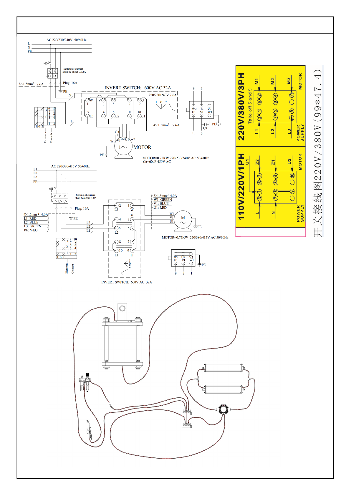
13. Diagram
110V / 220V
380V
Table of contents
Popular Tyre Changer manuals by other brands


Snap-On
Snap-On EEWH311B Operation instructions

Butler
Butler NAV11N instruction manual

Dunlop
Dunlop DTM590 instruction manual

Coats
Coats 80C operating instructions

HENNESSY INDUSTRIES
HENNESSY INDUSTRIES Coats 4050A Safety Instructions, Operating Instructions, Installation Instructions, Maintenance Instructions

Fasep
Fasep RGU600E instruction manual


