Black Diamond Video DVI Converters Original operating instructions

DVI Converters: Installation &
Operation Guide
Edition 1.01
August 2007
BDV
BLACK DIAMOND VIDEO

Edition 1.01 DVI Converters: Installation & Operation Guide

DVI Converters - Installation & Operation Guide Edition 1.01 Contents i
. . . . .
. . . . . . . . . . . . . . . . . . . . . . . . . . . . . . . . . . .
Contents
Chapter 1 Product Information ................................ 1
About DVI Converters ............................................ 1
Options .................................................................... 1
Key Features & Specifications ................................ 2
Output Panel Detail ................................................. 2
Video Input Detail ................................................... 3
Customer Service and Support ................................ 4
Chapter 2 Installation Instructions.......................... 7
SD-DVI Converter Installation ................................ 7
SDI-DVI Converter Installation .............................. 9
RGB-DVI Converter Installation .......................... 10
RS-232 Control ...................................................... 11
Chapter 3 Using the Control Buttons ....................13
About the Control Buttons ..................................... 13
Selecting Adjustment Modes ................................. 14
RGB-DVI Converter Adjustment Modes.............. 15
SD-DVI Converter Adjustment Modes ................. 16
Restoring Factory Defaults.................................... 17
Auto Increment & Decrement ............................... 18
Appendix A RS-232 Protocol ........................................19
DVI Converters Command Set .............................. 19

ii Contents Edition 1.01 DVI Converters - Installation & Operation Guide
DVI Converters - Installation & Operation Guide Edition 1.01 Introduction 1
. . . . .
. . . . . . . . . . . . . . . . . . . . . . . . . . . . . . . . . . .
P
RODUCT
I
NFORMATION
1
. . . . . . . . . . . . . . . . . . . . . . . . . . . . . . . . . . . . . . . . . . . . . . . . . . . .
ABOUT DVI CONVERTERS
Black Diamond Video offers a line of single-link DVI converters which you can use to
convert your RGB, SD, and SDI video signals to single-link DVI. With the appropriate DVI
converter, you can use any of these alternate video formats as an input source for Black
Diamond Video digital video processing equipment.
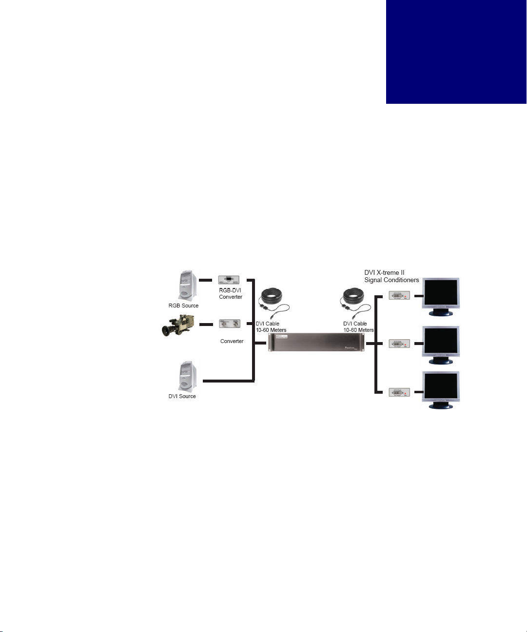
The system diagram (Figure 1) illustrates the full functionality of a DVI processor when
combined with Black Diamond Video's DVI Converters and DVI X-treme Cable Kits.
. . . . . . . . . . . . . . . . . . . . . . . . . . . . . . . . . . . . . . . . . . . . . . . . . . . .
OPTIONS
The following DVI converters are available:
•SD-DVI Converter converts any standard-definition analog signal (NTSC, PAL,
SECAM) to DVI. This converter is controlled and integrates seamlessly with Black
Diamond Video digital video processing equipment.
•SDI-DVI Converter converts any serial digital interface signal (SDI) to DVI. This
converter is integrates seamlessly with Black Diamond Video digital video processing
equipment.
FIGURE 1. System diagram using DVI Converters
NTSC Source
SD-DVI
DVI Processor

PRODUCT INFORMATION
Key Features & Specifications
2Introduction Edition 1.01 DVI Converters - Installation & Operation Guide
•RGB-DVI Converter converts any analog RGB signal to DVI. This converter is
controlled and integrates seamlessly with Black Diamond Video digital video processing
equipment.
. . . . . . . . . . . . . . . . . . . . . . . . . . . . . . . . . . . . . . . . . . . . . . . . . . . .
KEY FEATURES & SPECIFICATIONS
Features and specifications include the following:
VIDEO INPUT
•SD-DVI Converter accepts any standard-definition analog signal (NTSC, PAL,
SECAM). Connectors: 3 BNCs: Composite Video, S-Luma, S-Chroma; Y,Cb,Cr.
• SDI-DVI Converter accepts any serial digital interface signal (SDI). Connector: 75
Ohm BNC input connector; DVI-D, 75 Ohm BNC output connector for loop-through.
•RGB-DVI Converter accepts any analog RGB signal. Connector: DB15 RGB.
VIDEO OUTPUT
• Single-link DVI. Connector: DVI Female.
CONTROL
• RS-232 serial control of the of the RBG-DVI and SD-DVI Converters. Connector: RJ11.
An RJ11 to DB9 female serial cable is included with all converters.
• Manual control of the RBG-DVI and SD-DVI Converters using external mode setting
and selection buttons.
POWER
• Converters are equipped with a +5V AC/DC adapter.
. . . . . . . . . . . . . . . . . . . . . . . . . . . . . . . . . . . . . . . . . . . . . . . . . . . .
OUTPUT PANEL DETAIL
Figure 2 details the DVI output panel of the RGB-DVI, SD-DVI, and SDI-DVI converters.
This panel also contains the power input connector and the Link status LED. The Link
status LED indicates a variety of status and functions by the color and pattern of the light.

. . . . .
PRODUCT INFORMATION
Video Input Detail
DVI Converters - Installation & Operation Guide Edition 1.01 Introduction 3
For example, the LED flashes a red blinking pattern to indicate an active video input
connection exists.
. . . . . . . . . . . . . . . . . . . . . . . . . . . . . . . . . . . . . . . . . . . . . . . . . . . .
VIDEO INPUT DETAIL
Figure 3 details the video input panel of the RGB-DVI Converter.
FIGURE 2. DVI output panel
FIGURE 3. RGB/YUV input panel of the RGB-DVI Converter

PRODUCT INFORMATION
Customer Service and Support
4Introduction Edition 1.01 DVI Converters - Installation & Operation Guide
Figure 4 details the video input panel of the SD-DVI Converter.
Figure 5 details the video input panel of the SDI-DVI Converter.
. . . . . . . . . . . . . . . . . . . . . . . . . . . . . . . . . . . . . . . . . . . . . . . . . . . .
CUSTOMER SERVICE AND SUPPORT
For technical support and service, contact Black Diamond Video at:
Black Diamond Video
1151 Harbor Bay Parkway, Suite 208
Alameda, California, 94501
Phone: (510) 769-2959
Fax: (510) 769-2949
Visit us on the web at www.blackdiamondvideo.com.
FIGURE 4. Input panel of the SD-DVI Converter
FIGURE 5. Input panel of the SDI-DVI Converter

. . . . .
PRODUCT INFORMATION
Customer Service and Support
DVI Converters - Installation & Operation Guide Edition 1.01 Introduction 5

PRODUCT INFORMATION
Customer Service and Support
6Introduction Edition 1.01 DVI Converters - Installation & Operation Guide

DVI Converters - Installation & Operation Guide Edition 1.01 Installation 7
. . . . .
. . . . . . . . . . . . . . . . . . . . . . . . . . . . . . . . . . .
I
NSTALLATION
I
NSTRUCTIONS
2
This chapter tells you how to install your SD-DVI, SDI-DVI, or RGB-DVI converter.
. . . . . . . . . . . . . . . . . . . . . . . . . . . . . . . . . . . . . . . . . . . . . . . . . . . .
SD-DVI CONVERTER INSTALLATION
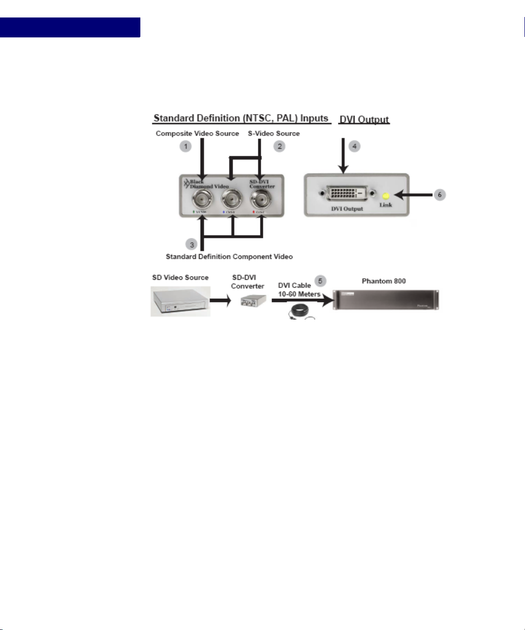
Figure 6 illustrates the installation of the SD-DVI converter. The following procedure
describes the installation process.
IMPORTANT!
This product must be tested with the intended equipment
before being permanently installed. Failure to do so voids any
warranty and limited liability. Although Black Diamond Video
tests the product to its fullest extent, situations may arise
giving marginal results or potential compatibility issues when
used with digital video display devices that are non-compliant
or incompatible.
NOTE: DVI Converters should be connected as close to the video source as
possible to minimize cable problems such as noise and attenuation.
INSTALLATION INSTRUCTIONS
SD-DVI Converter Installation
8Installation Edition 1.01 DVI Converters - Installation & Operation Guide
To Install the SD-DVI Converter
Before installing the SD-DVI converter, connect the supplied power adapter to the unit and
plug it into an AC power source. Black Diamond Video recommends the use of a surge
protector.
1Connect composite video sources to the BNC connector labeled “Y/CVBS”.
2Connect S-Video sources to the BNC connectors labeled “Cb/S-Y” and “Cr/S-C”
3Connect component sources to the BNC connectors “Y/CVBS”, “Cb/S-Y” and “Cr/S-C”.
4Connect the DVI output of the converter to a Black Diamond Video-tested DVI cable.
5Connect the other end of the DVI cable directly to the Black Diamond Video digital
video processing equipment in your installation, such as the Phantom 800 or CXPS.
6The Link LED indicator on the converter flashes green when an active connection to
the converter is established.
Installation of the SD-DVI Converter is complete.
FIGURE 6. SD-DVI Converter installation

. . . . .
INSTALLATION INSTRUCTIONS
SDI-DVI Converter Installation
DVI Converters - Installation & Operation Guide Edition 1.01 Installation 9
. . . . . . . . . . . . . . . . . . . . . . . . . . . . . . . . . . . . . . . . . . . . . . . . . . . .
SDI-DVI CONVERTER INSTALLATION
Figure 7 illustrates the installation of the SDI-DVI converter. The following procedure
describes the installation process.
To Install the SDI-DVI Converter
Before installing the SDI-DVI converter, connect the supplied power adapter to the unit and
plug it into an AC power source. Black Diamond Video recommends the use of a surge
protector.
1Connect the 75 Ohm Serial Digital Interface source to the BNC connector labeled SDI
Input.
2If desired, connect a 75 Ohm Serial Digital Interface output to the BNC connector
labeled SDI Output for loop-through connection to the SDI source.
3Connect the DVI output of the converter to a Black Diamond Video-tested DVI cable.
4Connect the other end of the DVI cable directly to the Black Diamond Video digital
video processing equipment in your installation, such as the Phantom 800 or CXPS.
5The Link LED indicator on the converter flashes green when an active connection to
the converter is established.
NOTE: DVI Converters should be connected as close to the video source as
possible to minimize cable problems such as noise and attenuation.
FIGURE 7. SDI-DVI Converter installation
INSTALLATION INSTRUCTIONS
RGB-DVI Converter Installation
10 Installation Edition 1.01 DVI Converters - Installation & Operation Guide
Installation of the SDI-DVI Converter is complete.
. . . . . . . . . . . . . . . . . . . . . . . . . . . . . . . . . . . . . . . . . . . . . . . . . . . .
RGB-DVI CONVERTER INSTALLATION
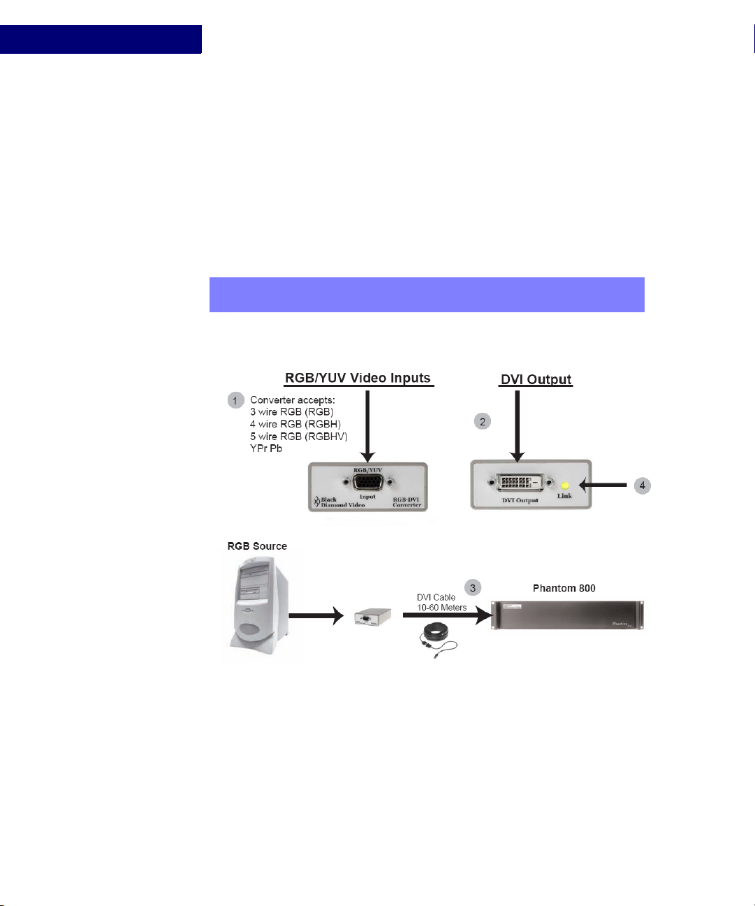
Figure 8 illustrates the installation of the RGB-DVI converter. The following procedure
describes the installation process.
To Install the RGB-DVI Converter
Before installing the SD-DVI converter, connect the supplied power adapter to the unit and
plug it into an AC power source. Black Diamond Video recommends the use of a surge
protector.
1Connect 3 wire, 4 wire, or 5 wire RGB or YUV source to the DB15 HD connector labelled
“RGB/YUV”.
2Connect the DVI output of the converter to a Black Diamond Video-tested DVI cable.
NOTE: DVI Converters should be connected as close to the video source as
possible to minimize cable problems such as noise and attenuation.
FIGURE 8. RGB-DVI Converter installation

. . . . .
INSTALLATION INSTRUCTIONS
RS-232 Control
DVI Converters - Installation & Operation Guide Edition 1.01 Installation 11
3Connect the other end of the DVI cable directly to the Black Diamond Video digital
video processing equipment in your installation, such as the Phantom 800 or CXPS.
4The Link LED indicator on the converter flashes green when an active connection to
the converter is established.
Installation of the RGB-DVI Converter is complete.
. . . . . . . . . . . . . . . . . . . . . . . . . . . . . . . . . . . . . . . . . . . . . . . . . . . .
RS-232 CONTROL
Set up of the RGB-DVI and SD-DVI converters should be done using RS-232 control. The
following procedure details how to establish RS-232 serial control with the DVI converter.
To establish RS-232 control of the DVI converter
1Connect the supplied RJ11 to DB9 cable to the DVI converter.
2Connect the control computer to the RS-232 DB9 connector on the supplied cable. DVI
Converters.
3Open up a serial port terminal on the control computer.
On Microsoft Windows, you can use HyperTerminal for serial communications.
4Configure the port settings as follows:
• Baud: 9600
• Data bits: 8
• Parity: None
• Stop bits: 1
• Flow control: None
The RS-232 connection to the DVI Converters is established and the converter can be con-
trolled using the RS-232 command set found in Appendix A, “RS-232 Protocol.”
NOTE: To avoid recreating the connection parameters each time you reestablish
RS-232 connection to the CXPS, you can save the connection for
subsequent control sessions.

INSTALLATION INSTRUCTIONS
RS-232 Control
12 Installation Edition 1.01 DVI Converters - Installation & Operation Guide
DVI Converters - Installation & Operation Guide Edition 1.01 Operation 13
. . . . .
. . . . . . . . . . . . . . . . . . . . . . . . . . . . . . . . . . .
U
SING
THE
C
ONTROL
B
UTTONS
3
This chapter tells you how to use the control buttons on the RGB-DVI and SD-DVI
Converters.
. . . . . . . . . . . . . . . . . . . . . . . . . . . . . . . . . . . . . . . . . . . . . . . . . . . .
ABOUT THE CONTROL BUTTONS
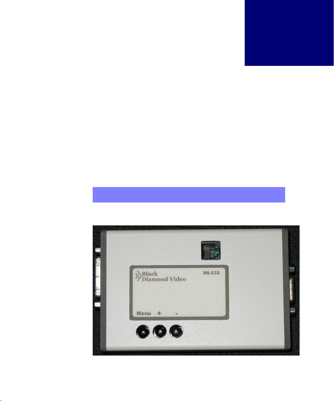
The RGB-DVI and SD-DVI Converters have three buttons you can use to modify settings
on the devices. The buttons are labeled down (−), up (+), and Menu. Figure 9 shows the
top of the converters and the three control buttons.
The Link LED, located on the DVI output panel, flashes in different colors and patterns to
indicate the current mode setting.
NOTE: You can also use RS-232 control to control the Converter. See Appendix A,
“RS-232 Protocol,” for details.
FIGURE 9. Converter Control Buttons

USING THE CONTROL BUTTONS
Selecting Adjustment Modes
14 Operation Edition 1.01 DVI Converters - Installation & Operation Guide
NORMAL OPERATION MODE
When either of the two converters is in normal operation mode, the LED flashes in a pattern
of two blinks, followed by three blinks, followed by four blinks. The LED color is red if the
device is locked to an input or green if the device does not detect a valid input.
ADJUSTMENT MODES
You can use the control buttons to modify various settings on the Converters. The buttons
are used to enter the different adjustment modes, such as Modulus and Horz. Position for the
RGB-DVI Converter and Saturation and Contrast for the SD-DVI Converter, and make
setting changes.
. . . . . . . . . . . . . . . . . . . . . . . . . . . . . . . . . . . . . . . . . . . . . . . . . . . .
SELECTING ADJUSTMENT MODES
The adjustment modes and how to select them are listed in the following table. For more
information about the adjustment modes, see “RGB-DVI Converter Adjustment Modes” on
page 15 and “SD-DVI Converter Adjustment Modes” on page 16.
To Select an Adjustment Mode
•To enter an adjustment mode that allows you to modify one of the device settings, hold
one or more buttons down for three seconds.
When the device is in the new setting mode, the LED blink pattern and/or color changes.
Press and Hold 3
Seconds to Enter
Mode
Adjustment Mode:
RGB-DVI Converter
Adjustment Mode:
SD-DVI Converter LED pattern/color
Auto
Increment &
Decrement?a
a. For more information on Auto Increment & Decrement, see “Auto Increment & Decrement” on page 18.
. . . . . . . . . . . . .
. . . . . . . . . . . . . . .
. . . . . . . . . . . . . .
. . . . . . . . . . . . .
. . . . . . . . . .
−Modulus Brightness Rapid Red blink Yes
+Phase Contrast Rapid Green blink Yes for SD
−and +Test Pattern Input Format Steady Green b
b. For the SD-DVI Converter, the LED pattern/color is Steady Green if the unit is in AutoSense mode. However, depending on the Input Format
setting (see below), the LED is Steady Green but may flicker several times every 3-4 seconds.
No
Menu and −Horiz. Position Saturation Red, Red, Green Yes for SD
Menu and +Vert. Position Hue Green, Green, Red Yes for SD
Menu and +and −Test Pattern Rotate N/A Steady Green No
Menu Restore Factory
Defaults
Restore Factory
Defaults
Steady Red c
c. The Restore Factory Defaults mode is special, but begins with the LED pattern and color in Steady Red mode. See “Restoring Factory Defaults”
on page 17.
No

. . . . .
USING THE CONTROL BUTTONS
RGB-DVI Converter Adjustment Modes
DVI Converters - Installation & Operation Guide Edition 1.01 Operation 15
For example, if you want to change the input modulus on an RGB to DVI converter unit,
press and hold the Down (−) button until the LED blink pattern changed to a rapid red
blinking pattern (about 3 seconds). At this point, the up and down buttons would set the
modulus up and down.
To Exit an Adjustment Mode
•To exit any of the adjustment modes, hold down the Menu button until the normal
operation mode LED blink pattern returns (about 3 seconds).
. . . . . . . . . . . . . . . . . . . . . . . . . . . . . . . . . . . . . . . . . . . . . . . . . . . .
RGB-DVI CONVERTER ADJUSTMENT MODES
There are six adjustment modes for the RGB-DVI Converter.
MODULUS
Use this adjustment mode to modify the modulus applied to the RGB input signal.
PHASE
Use this adjustment mode to modify the phase applied to the RGB input signal.
TEST PATTERN
The RGB converter unit can generate nine different test patterns. In Test Pattern mode, you
can select the output test pattern to be generated. The default output resolution is 640 x 480.
Additional output resolutions are available via serial command. (See the
inputtestpattern command in Appendix A, “RS-232 Protocol.”)
HORIZONTAL POSITION
In this mode, you can adjust the horizontal position of the RGB input relative to the output.
VERTICAL POSITION
In this mode, you can adjust the vertical position of the RGB input relative to the output.
TEST PATTERN ROTATE
In this mode, each of the nine test patterns are displayed at a resolution of 640 x 480. Each
test pattern remains on the output for approximately five seconds.
NOTE: The changes that these adjustment modes make to the device can be seen
immediately, but the changes are not be stored to non-volatile memory until
you exit the adjustment mode and return to the normal operation mode. If
the unit is powered off before the normal mode is re-entered, the changes
made in the last adjustment mode are lost.

USING THE CONTROL BUTTONS
SD-DVI Converter Adjustment Modes
16 Operation Edition 1.01 DVI Converters - Installation & Operation Guide
. . . . . . . . . . . . . . . . . . . . . . . . . . . . . . . . . . . . . . . . . . . . . . . . . . . .
SD-DVI CONVERTER ADJUSTMENT MODES
There are five adjustment modes specific to the SD-DVI Converter:
BRIGHTNESS
In this mode, you can adjust the brightness setting for the converter.
CONTRAST
In this mode, you can adjust the contrast setting for the converter.
INPUT FORMAT
The SD-DVI Converter has an input format setting that can be set to one of four possible
values. By default, your converter is set to AutoSense input format. You can tell which
format has been selected by the LED blink pattern:
•AutoSense - detects if either a composite or svideo signal is present and automatically
selects the correct input format. The LED blink pattern is solid red.
•Composite - sets the input format to Composite. The LED blink pattern is solid red, but
the light flickers off once approximately every three to four seconds.
•Svideo - sets the input format to SVideo. The LED blink pattern is solid red, but the light
flickers off two times every three to four seconds.
•Component - sets the input format to Component. The LED blink pattern is solid red,
but the light flickers off three times every three to four seconds.
Setting the device to either Composite, Svideo, or Component will disable AutoSense mode
and force the particular input setting, even if no signal is present in that input format.
To Set the Input Format
1Press and hold - and +for three seconds.
The LED pattern is Steady Green, indicating the input format adjustment mode is active.
2Press the + button to move up through the format settings, from AutoSense to
Composite, from Composite to Svideo, or from Svideo to Component.
3Press the − button, to move down through the format settings, from Component to
Svideo, Svideo to Composite, or Composite to AutoSense.
NOTE: Autosense, due to hardware limitations, cannot detect component video
input. If you are using a component video input, you must set the input
format specifically to Component.
This manual suits for next models
3
Table of contents


