ROJEK a.s. 4 FSN 300A
Foreword
These instructions have been created by the device manufacturer and are an integral part of the ma-
chine delivery. They contain basic information for qualified operating staff and describe the environ-
ment and manners of the machine use for which it has been designed, and also contain any informa-
tion necessary for the correct and safe operation.
The machine is equipped with various safety devices protecting both the operator and the machine for
its common technological use. Nevertheless these measures cannot cover all safety aspects and there-
fore it is necessary that the operator should read and understand these instructions before starting to
use the machine. Errors made in the course of installation as well as during operation itself will thus
be avoided.
Do not try therefore to put the machine into operation before you have read all instructions
for use supplied together with the machine and before you have understood all its functions and
working procedures.
Certain information or drawings may not be intended directly for the machine purchased by you as
these instructions contain any information for various variants of this type made by our company. By
comparing the respective part of the instructions with a particular machine you will find out whether
or not they correspond to each other.
The manufacturer reserves the right to make partial alterations within continuous technical machine
development.
For emphasis of important passages in the basic text the bald characters and marking with a certain of
the following symbols have been used:
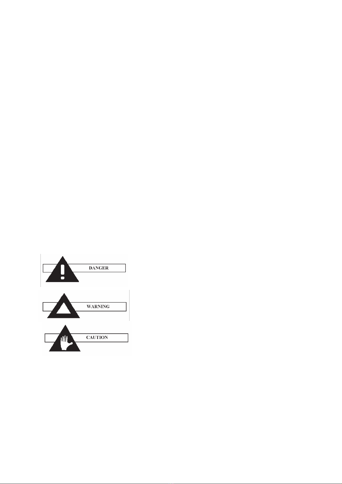
The appeal recommending to use the procedure according to the
following regulation exclusively. A failure to observe this regula-
tion may result in death or serious injuries of the operating staff.
A warning against improper working procedures or use of the
machine that may cause a danger to human health, machine func-
tioning, the environment or economic losses.
Caution is an appeal to take due care while the following activi-
ties are being performed. Any failure to comply with this appeal
may cause small injuries or damage to the machine.
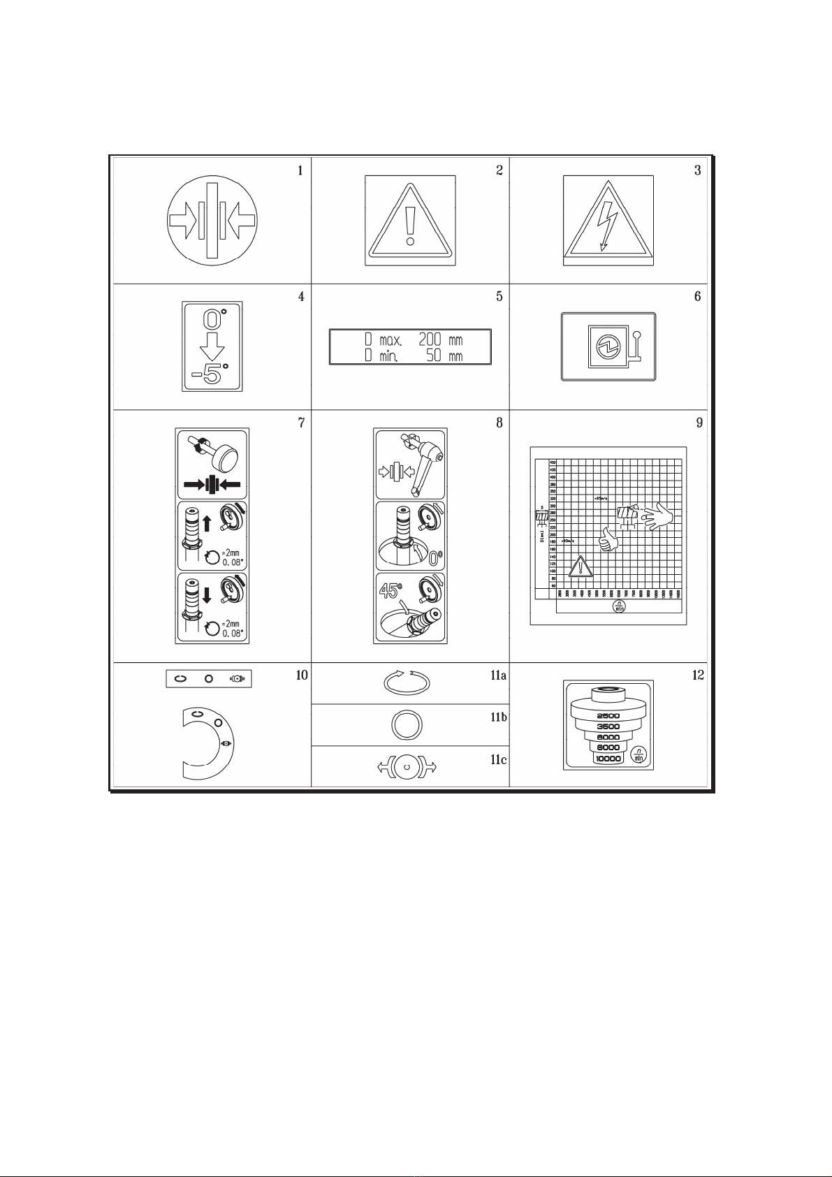
Follow the instructions shown on the plates with which the ma-
chine is equipped. Do not remove or damage such plates. In the case of any damage caused to the
plate contact the manufacture and renew the plate.
Note
The text and picture part of the instructions is an intellectual property of the ROJEK Co.
and will remain in the company´s ownership. No part of the instructions may be copied
or reproduced without a prior consent nor any third persons are allowed to become
acquainted with these instructions or with any part thereof.