MAINTENANCE
8. If the cartridge remains in the pump casing, grasp the shaft
and/or liner and pull while slightly turning back and forth. If
necessary, GENTLY tap around the circumference with a
rubber mallet to loosen the cartridge assembly. Be sure to
keep it concentric with the bore. DO NOT PRY THE
CARTRIDGE OUT AGAINST THE SIDE WALLS AS THE
GASKET SEAL SURFACE WILL BE DAMAGED.
PUMP CARTRIDGE INSTALLATION
1. Install the wave spring (6) in the cartridge bore with the
dowel pin hole exposed by the gap in the wave spring.
2. Lightly grease the lip seal O-rings.
3. Align the pump cartridge dowel pin with the dowel pin hole
and slide in the pump cartridge (7). If the pin is in the hole,
you should be able to rotate the cartridge very lightly back
and forth and feel the positive stops. The wave spring
deflection will also be felt when the cartridge is pressed in
axially. PUMP WILL NOT BUILD IF THE CARTRIDGE PIN
IS NOT IN THE HOLE.
4. Insert provided guides into screw holes. The guides will
orient gasket as well as hold it in position.
5. Install the head gasket (8). If needed, apply a thin film of
motor oil onto the mating surface to affix areas of the
gasket that do not retain their position.
6. Carefully install the head (9) over the cartridge. Push head
in until it comes approximately 1/4” from the casing face.
7. Carefully replace guides with head screws, threading each
of them in a few turns.
8. Alternating between the four screws closest to the shaft,
draw in the head approximately one turn on the screw at a
time in order to keep the head parallel to the casing.
NOTE: Screws will become very tight if faces are not kept
parallel. If necessary, go back to step 3 and check to
ensure the cartridge pin is still aligned with the hole.
9. Once the head is fully drawn in, torque the four screws to
200 lbs-in (23 Nm).
10.Before tightening the remaining head screws, check that
the pump shaft turns freely and uniformly. If so, tighten the
remaining screws to 200 lbs-in (23 Nm).
11. Reinstall inlet check valve, strainer and pressure control
valve according to previous instructions.
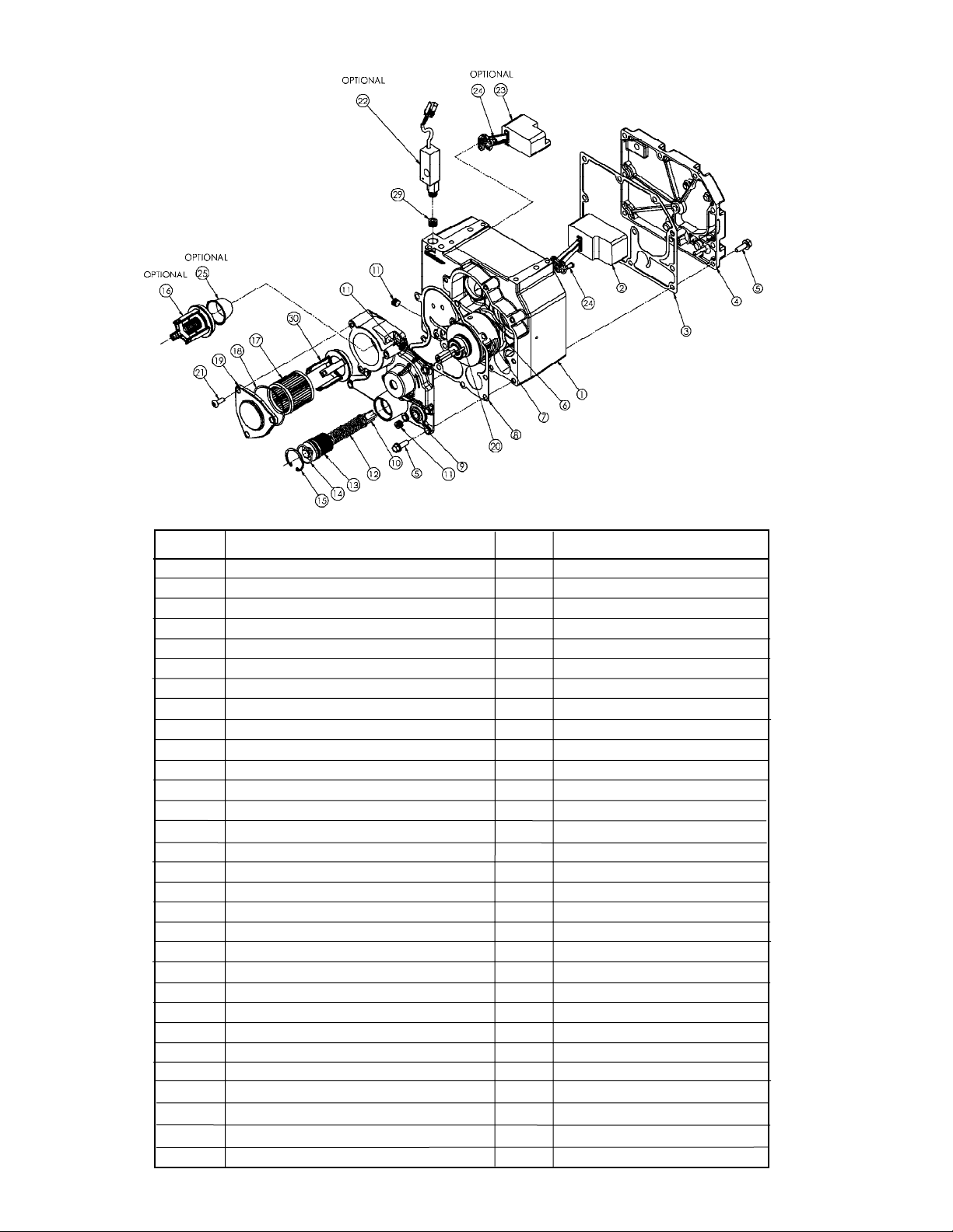
SUMP FLOAT REMOVAL
Pump will have poor suction or sump overflow if sump float
mechanism is worn or damaged
Tools Required: 13 mm Socket Wrench (or 1/2” Socket Wrench)
4 mm Allen Wrench
1. Drain the pump following the procedure outlined under the
“Draining Pump” section.
2. Remove the pump from the dispenser per dispenser
installation instructions.
3. Remove the ten (10) sump cover screws (5).
4. Lift off the sump cover (4) and gasket (3). Inspect gasket
and replace if worn or damaged.
5. The sump return float mechanism should operate freely. At
full down position, the float valve should center and seat
against the rubber seal surface. If it does not seat, or parts
are worn or damaged, remove the sump float assembly
and replace.
The sump overflow float mechanism (if present) should
operate freely. The float valve should center and seat
against the rubber seal surface when float is lifted straight
up.
Either the sump float assembly (2) or the sump overflow
float mechanism (23) can be removed by removing the two
sump base mounting screws (24).
SUMP FLOAT INSTALLATION
1. Install the sump return float assembly (2) or sump overflow
float assembly (23), holding the mount to the casing with
one finger and inserting the two screws (24) with the other
hand. Take care the rubber washer has not fallen out and
is properly seated in the recess of the float assembly
mount. See Figure 4.
2. Tighten the screws (24) to a torque of 18 lbs-in (2 Nm).
3. Check float mechanism. It should operate freely.
At full down position, the sump return float valve should
center and seal against the rubber seal surface.
The sump overflow float assembly should seat when the
float is fully elevated.
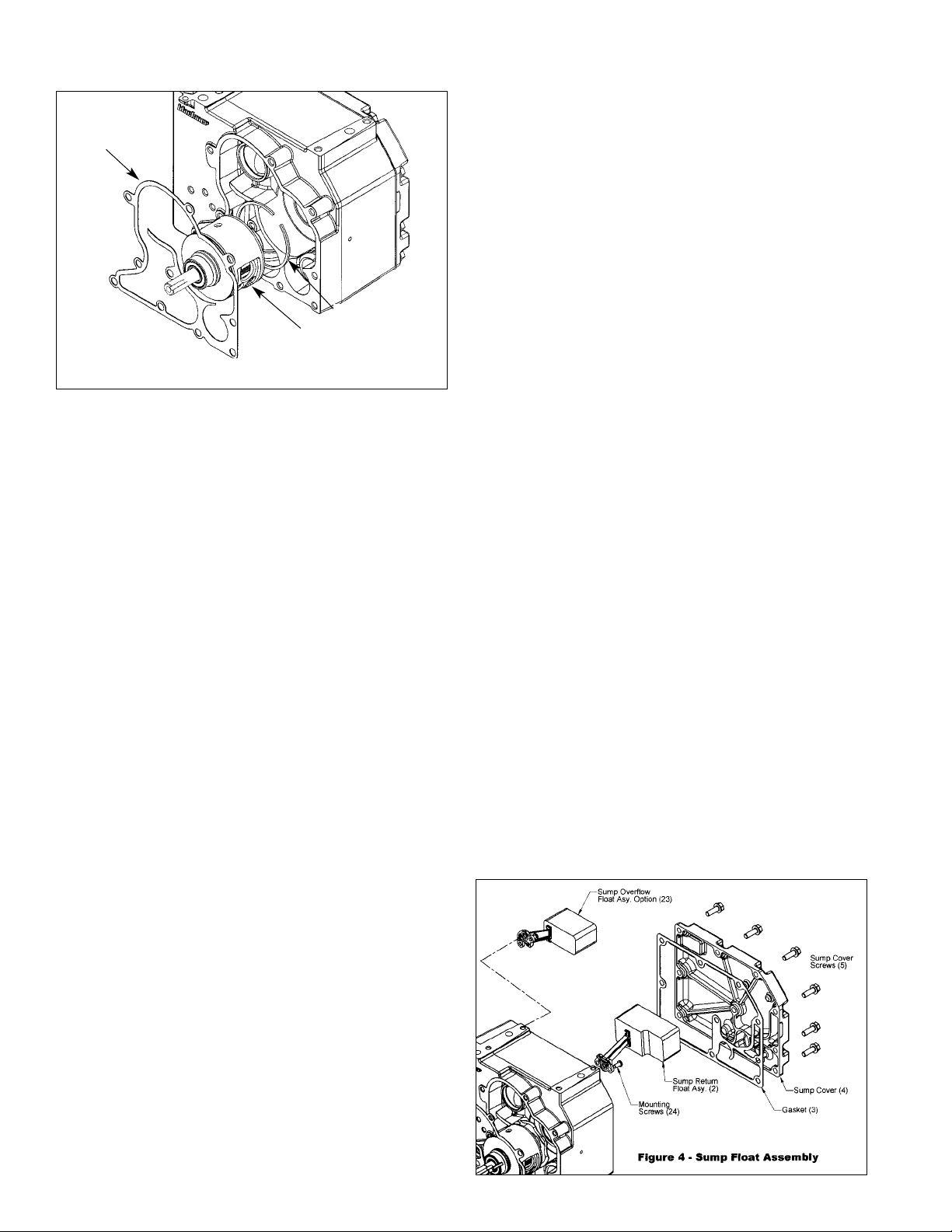
Figure 3 - Pump Cartridge
4
Wave Spring (6)
Pump Cartridge (7)
Head Gasket (8)