Blacoh Sentry XPB User manual

SENTRY™ dampeners are pressure vessels containing a exible bladder or bellows inside that separates an inert pressurized gas
(air or Nitrogen) from a system uid in the lower chamber. Depending on how dampeners are congured, they are used as Pulsation
Dampeners, Inlet Stabilizers or Surge Suppressors to control pressure uctuations and spikes in liquid piping systems.
Dampeners work on the principle that volume is inversely proportional to pressure (P1V1=P2V2). Compressed air or Nitrogen (never
Oxygen) is introduced into the non-wetted side of the dampener. The gas charge is contained by the bladder or bellows preventing
contact between the system uid and the gas.
When the dampener is sized correctly, properly installed and charged according to the instructions provided it will greatly reduce the
damaging eects of pressure variations in piping systems and signicantly improve the eciency of transferring liquids.
All dampeners manufactured by BLACOH use pressure bodies made in the USA to ensure quality. Prior to shipment, each
and every dampener is factory pressure tested to assure proper function and leak-free operation.
Visit Blacoh.com for literature in multiple languages.
XP High Pressure Dampeners
XPB, XPHB & XPXB Models
Installation and Operation Manual

Copyright © 2022 BLACOH Fluid Controls, Inc. All rights reserved.
Information in this document is subject to change without notice. No part of this publication may be reproduced, stored in a retrieval system or transmitted in any
form or by any means electronic or mechanical, including photocopying and recording for any purpose other than the purchaser’s personal use without the express
written permission of BLACOH Fluid Controls, Inc.
The word “dampener”, as used in this Manual, has the same meaning as Pulsation Dampener, Inlet Stabilizer or Surge Suppressor.
Depending on the specic model, the word “bladder” is used to reference dampener elastomeric bladders or diaphragms. Unless
otherwise specied, the word “bellows” refers to both PTFE and Stainless Steel metal bellows.
MODEL Specications & Installation Information
Model No. Serial No. Installation Date
Body Material: Wetted / Non-wetted Bladder / Bellows Material Pump Area and Number
Purchased From Contact Phone Email
1BLACOH Industries
Table of Contents
SAFETY Warnings ����������������������������������������������������������������������������������������������������������������������������������������������������������������2
Safety Symbols ............................................................................................................................................... 2
General Safety ................................................................................................................................................ 2
Equipment Misuse Hazard..............................................................................................................................2
GENERAL Information ���������������������������������������������������������������������������������������������������������������������������������������������������������2
Must Read Before Installation.........................................................................................................................3
Installation Notes.............................................................................................................................................3
ATEX Standard ...............................................................................................................................................3
Maintenance....................................................................................................................................................3
Temperature Limits..........................................................................................................................................4
Installation & Operation Instructions ���������������������������������������������������������������������������������������������������������������������������������5
Pre-Charge Notes ........................................................................................................................................... 5
Charging Instructions ...................................................................................................................................... 5
Pressure Seal Check ......................................................................................................................................6
Installation for Pump Discharge Pulsation ......................................................................................................6
Maintenance, Inspection & Repair ..................................................................................................................7
Gauge Adapter Assembly Installation ........................................................................................................... 11
Manufacturer’s Limited Warranty & Return Policy���������������������������������������������������������������������������������������������������������� 11

2BLACOH Industries
WARNINGS Danger of serious injury or death could occur if these warnings are ignored.
CAUTIONS Equipment damage, injury or death could occur if these cautions are not observed.
NOTES Special instructions for safe and satisfactory installation, operation and maintenance.
SAFETY Warnings
Dampeners should only be installed, operated and repaired by experienced and trained professional mechanics. Read and observe all
instructions and safety warnings in this Manual before installing, operating or repairing dampeners.
Safety Symbols
The following symbols indicate cautions, warnings and notes that must be observed for safe and satisfactory installation, operation and
maintenance of dampener.
GENERAL Information
For safe and satisfactory operation of dampener read all safety warnings, caution statements and this complete Manual before installation,
startup, operation or maintenance.
▪Observe all safety symbols in installation and operation instructions.
▪ The internal dampener pressure will equal the maximum uid
pressure of the system in which it is installed.
▪DO NOT exceed maximum allowable working pressure (MAWP)
specied on dampener serial tag or marked on dampener. If
missing, DO NOT use dampener without consulting distributor or
factory for maximum pressure rating.
▪ Always make sure safety shuto valves, regulators, pressure relief
valves, gauges, etc. are working properly before starting system or
assembly.
▪Verify dampener model received against purchase order and
shipper.
▪Before starting a system or assembly make certain the discharge
point of the piping system is clear and safe, and all persons have
been warned to stand clear.
▪DO NOT put your face or body near dampener when the system or
assembly is operating or dampener is pressurized.
▪DO NOT operate a dampener that is leaking, damaged, corroded or
otherwise unable to contain internal uid, air or gas pressure.
▪DO NOT pump incompatible uids through dampener. Consult
distributor or factory if you are not sure of the compatibility of
system uids with dampener materials.
▪Dampeners are designed to operate with compressed air or clean
dry Nitrogen only. Other compressed gases have not been tested
and may be unsafe to use. DO NOT USE OXYGEN�
▪ Always shut o air supply, remove internal dampener pressure
and shut dampener isolation valve before performing dampener
maintenance or repair.
▪Remove all pressure from dampener AND pumping system before
disassembly, removal or maintenance.
▪Static spark can cause an explosion resulting in severe
injury or death� Ground dampeners and pumping system
when pumping ammable uids or operating in ammable
environments�
General Safety
General Safety
DO NOT misuse dampener, including but not limited to over-
pressurization, modication of parts, using incompatible chemicals, or
operating with worn or damaged parts. DO NOT use any gases other
than compressed air or clean dry Nitrogen to charge dampener. DO
NOT USE OXYGEN. Any misuse could result in serious bodily injury,
death, re, explosion or property damage.
Over-Pressurization
Never exceed the maximum pressure rating for the dampener
model being used. Maximum allowable working pressure (MAWP) is
specied on dampener serial tag or marked on dampener. Maximum
allowable working pressure (MAWP) is rated at 70°F (21°C).
Temperature Limits
DO NOT exceed the operating temperature limits for the body and/
or elastomer materials being used. Excessive temperature will result
in dampener failure. For temperature limits, refer to the “Temperature
Limits” section of this Manual. Temperature limits are stated at zero
psi/bar.
Installation and Startup Hazards
Install dampener before charging or pressurizing. DO NOT start
system or assembly without rst charging or pressurizing dampener.
Failure to charge may result in damage to the bladder or bellows.
Temperature & Pressure Hazard
Temperature and pressure reduce the strength and chemical
resistance of plastic, metal, elastomers and PTFE.
Charging / Pressurization
Charge or pressurize dampener with compressed air or clean dry
Nitrogen only. DO NOT USE OXYGEN�
Dampener Bladder/Bellows Failure
Dampeners utilize a bladder or bellows to separate system uid
from the air supply or gas charge. When failure occurs, system
uid may be expelled from the air valve. Always perform preventive
maintenance and replace bladder/bellows before excessive wear
occurs. O-rings for PTFE bellows and gaskets for Stainless Steel
metal bellows cannot be reused.
Maintenance Hazards
Never overtighten fasteners. This may cause leakage of system
uid and damage to dampener body. Bolts should not be reused as
re-torquing reduces bolt strength. After dampener maintenance or
disassembly, use new fasteners and torque fasteners according
to specication on dampener tag. If missing, consult distributor
or factory for torque specications.
Equipment Misuse Hazard

3BLACOH Industries
Maintenance
Remove all pressure from dampener AND pumping system before disassembly, removal or maintenance�
Dampeners require very little maintenance. There is no need for lubrication with bladders or bellows.
Elastomeric bladder replacement should be part of a preventive maintenance program. Dampeners used in conjunction with diaphragm pumps
should have the bladders replaced at least every second time the diaphragms in the pump are replaced. As with any pumping system, wear is
dependent on many factors including material, temperature, chemicals, uid abrasiveness and system design. This suggested maintenance
program may need to be adjusted according to specic applications.
Periodic inspection of the dampener and fasteners should be conducted to visually check for signs of over-pressurization, fatigue, stress or
corrosion. Body housings and fasteners must be replaced at rst indication of deterioration.
CAUTION! Replace nut and bolt fasteners at each reassembly with fasteners of equal grade/strength value� DO NOT reuse old
nuts and bolts�
After the initial torque of fasteners, bolts may lose strength when re-torqued. Failure to replace both nuts and bolts upon each vessel reassembly
will void the product warranty given by the manufacturer and the manufacturer will have no liability whatsoever for any vessel failure or
malfunction.
Where dampeners are used in corrosive environments, nut and bolt fasteners should be regularly inspected and replaced with nut and bolt
fasteners of equal grade/strength value if corrosion is observed. Failure to conduct such regular inspections and replacement will void the
product warranty given by the manufacturer and the manufacturer will have no liability whatsoever for any vessel failure or malfunction.
IMPORTANT! After maintenance or disassembly, use new fasteners and torque fasteners according to specication on dampener tag. If
missing, consult distributor or factory for specications.
DO NOT use dampener if the fasteners (nuts and bolts) are corroded. Check for fastener corrosion frequently, especially in atmospheres
containing salt or corrosive chemicals, or if dampener leakage has occurred.
Installation Notes
Dampening of ow pulsations can only be eective if a minimum of 5 to 10 psi (0.4 to 0.7 bar) back pressure downstream of dampener
is available. A BLACOH back pressure valve may be required downstream of dampener, except when dampener is used as an inlet
stabilizer for the inlet side of the pump.
It is recommended that a BLACOH pressure relief valve be installed in all pump systems to ensure compliance with pressure limits on
system equipment.
To avoid possible damage to bladder/bellows from a system pressure test:
Adjustable and Chargeable models — charge dampener to 80% of the system test pressure prior to test.
Automatic model — prior to test, dampener must be equipped with a constant source of compressed air with pressure equal to or
greater than system test pressure.
Inlet Stabilizer model — maximum pressure test 30 psi (2.0 bar), charge to 20 psi (1.3 bar) for system pressure test.
Install dampener inline as close to the pump discharge/inlet or quick closing valve as possible. Dampener installation should be no more
than ten pipe diameters from pump discharge/inlet or quick closing valve.
It is recommended that an isolation valve be installed between the dampener and system piping.
Must Read Before Installation
DO NOT use Oxygen to charge dampener. Use compressed
air or clean dry Nitrogen only.
DO NOT exceed maximum allowable working pressure
(MAWP) specied on dampener serial tag or marked on
dampener.
Turn pump o and remove all pressure from system prior to
dampener installation.
Always wear safety glasses and other appropriate safety
equipment when installing, charging or repairing dampener.
Danger of static spark! Grounding precautions must be
considered when dampener is used in ammable or explosive
environments.
Many plastics lose strength rapidly as temperature increases.
Consult factory if in doubt.
Temperature, pressure and chemicals aect the strength of
plastic, elastomer and metal components.
DO NOT operate a dampener that is leaking, damaged,
corroded or otherwise unable to contain internal uid, air or gas
pressure.
ATEX models must be grounded (earthed) before operation.
ATEX Standard
Certain models made for the European market are intended for use in potentially explosive atmospheres and meet the requirements of
ATEX directive 2014/34/EU. These models have the AT designation at the end of the part number, comply with ISO 80079-36, and have
an ATEX rating of II 2GD Ex h IIB T4 Gb Db. AT models have a grounding lug and must be grounded (earthed) before operation.

4BLACOH Industries
Temperature Limits
Operating temperatures are based on the maximum temperature of the wetted dampener components only. Non-wetted dampener
components may have a lower temperature limit. Temperature and certain chemicals may reduce the maximum allowable working pressure
(MAWP) of the dampener.
CAUTION! Plastic (non-metallic) body materials lose strength as temperature increases, which reduces the maximum pressure sustainable
by the material. All plastic materials must have an appropriate derating factor applied when working at elevated temperatures above 73.4°F
(23°C) to determine maximum allowable working pressure (MAWP).
Elastomer
Materials Temperature Limits Applications
Aas 0°F to +400°F (-18°C to +204°C) High temperature, petroleum based chemicals, strong acids and bases.
Buna-N +10°F to +180°F (-12°C to +82°C) Good ex life; use with petroleum, solvents and oil-based uids.
FDA Buna-N +10°F to +180°F (-12°C to +82°C) FDA-approved food grade; similar characteristics of regular Buna-N.
EPDM -60°F to +280°F (-51°C to +138°C) Use in extreme cold; good chemical resistance with ketones, caustics.
FDA EPDM -50°F to +225°F (-45°C to +107°C) FDA-approved food grade; similar characteristics of regular EPDM.
Hypalon -20°F to +275°F (-29°C to +135°C) Excellent abrasion resistance; good in aggressive acid applications.
Neoprene 0°F to +200°F (-18°C to +93°C) Good abrasion resistance and ex; use with moderate chemicals.
PTFE Diaphragm +40°F to +220°F (+4°C to +104°C) Use with highly aggressive uids.
PTFE Bellows -20°F to +220°F (-29°C to +104°C) Exclusive bellows design with excellent ex life; use with highly aggressive uids.
Santoprene -20°F to +225°F (-29°C to +107°C) Excellent choice as a low cost alternative for PTFE in many applications.
FDA Silicone -20°F to +300°F (-29°C to +149°C) FDA-approved food grade material; for use in food and pharmaceutical processing.
Viton®-10°F to +350°F (-23°C to +177°C) Use with hot and aggressive uids; good with aromatics, solvents, acids and oils.
Non-Metallic
Body Materials Temperature Limits Applications
Acetal* +32°F to +175°F (0°C to +79°C) Good ex life; low moisture sensitivity; high resistance to solvents and chemicals.
CPVC +32°F to +180°F (0°C to +82°C) Chlorinated PVC (CPVC): Good general chemical resistance; loses strength as
temperature rises.
Noryl +32°F to +220°F (0°C to +104°C) Good resistance to acids and bases; good temperature stability.
Polypropylene* +32°F to +175°F (0°C to +79°C) Good general purpose plastic; broad chemical compatibility at medium temperatures.
PTFE +40°F to +220°F (+4°C to +104°C) Use with highly aggressive uids, high temperatures.
PVC +32°F to +140°F (0°C to +60°C) Good general chemical resistance; loses strength as temperature rises.
PVDF +10°F to +200°F (-12°C to +93°C) Excellent resistance to most acids and bases; high temperatures.
* Conductive Acetal and Conductive Polypropylene available.
[T22E11_030]
Metal Bellows Temperature Limits Applications
SS w/Gaskets* -200°F to +800°F (-129°C to +426°C) Excellent for applications pumping frigid and molten uids, outdoor applications in
extreme temperatures, chemical applications where elastomers or PTFE would fail.
* Contact Blacoh for more information regarding temperatures below -200°F (-129°C).
Maximum allowable working pressure is reduced slightly for metal bellows at temperatures above 400°F (204°C). Apply an appropriate
derating factor to determine maximum allowable working pressure (MAWP).
5BLACOH Industries
Pre-Charge Notes
Pre-charge pressure should be checked at least monthly as gas molecules will diffuse through bladders/bellows, the speed of which depends
on the material, temperature and pressure. Checks must occur when no system pressure is present or inaccurate readings will be recorded.
If temperature is above 72°F (22°C) and/or pressure is over 300 psi (20.6 bar), checks should be performed more frequently. To prevent
pre-charge loss through the charging valve, always replace the charging valve cap after charging. A proper gas charge is the key to
dampener effectiveness and bladder/bellows life.
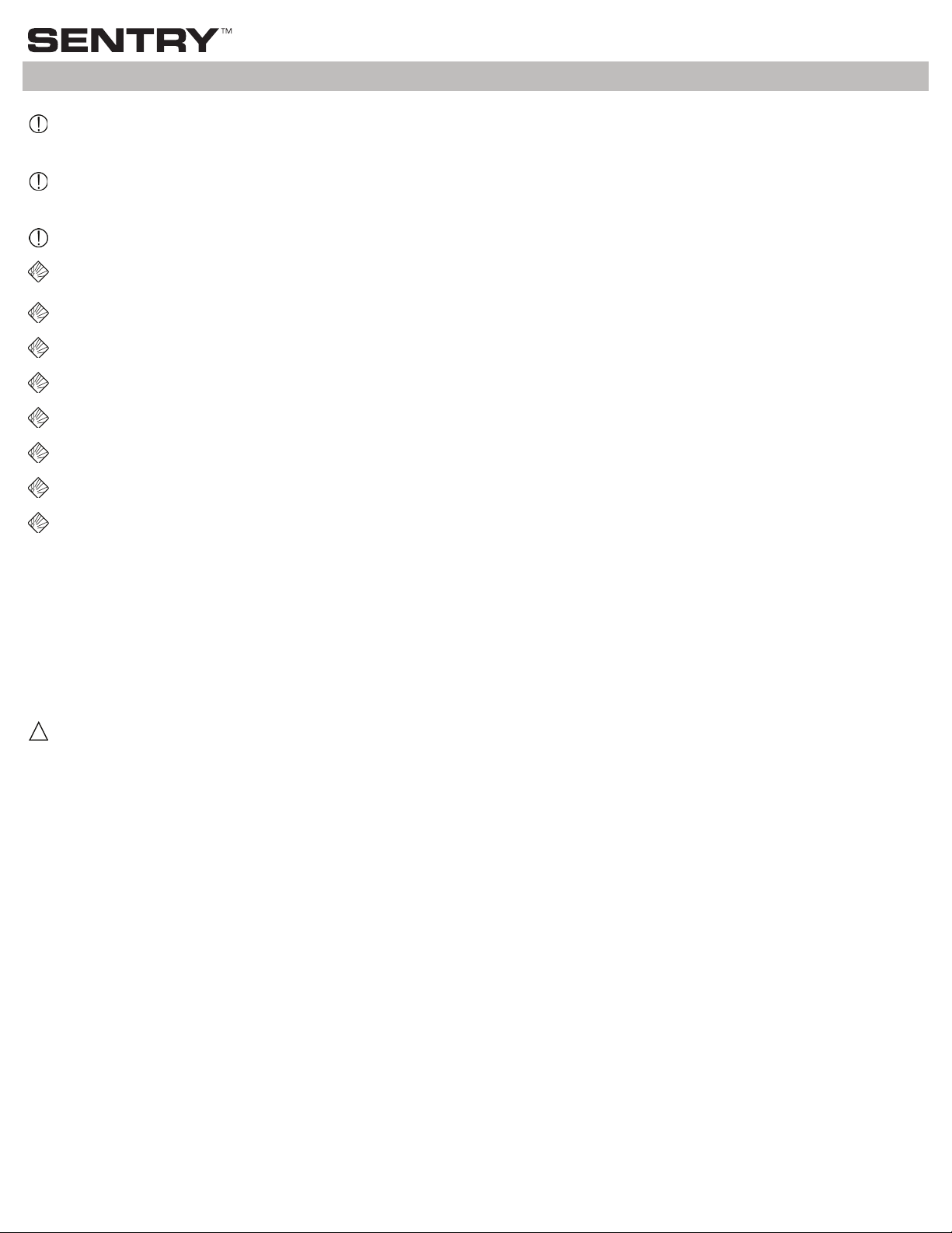
Charging Instructions
Dampener can only be properly charged when uid pressure is zero.
1. Point dampener charging valve in a safe direction. To verify dampener is not pressurized, remove charging valve cap and use a suitable
wrench to slowly open charging valve by turning valve opening nut counterclockwise (Figure 1).
2. Use a BLACOH high pressure XP Charging Kit or equivalent to charge dampener. Note: The source of Nitrogen (tank or bottle) must be
equipped with a regulator set at no more than the maximum allowable working pressure (MAWP) specied on dampener.
3. Close valve at Nitrogen source and thread charging hose connection securely to dampener charging valve. Make sure charging valve is
completely open by turning valve opening nut counterclockwise as far as it will go (Figure 1).
4. Slowly open valve at Nitrogen source and charge dampener to 100 psi (6.8 bar). Inspect charging valve and cap thread area for leaks by
spraying with a solution of soap and water. If any leaks are observed, remove pressure from dampener by slowly loosening charging hose
connection to charging valve or, if used, slowly open bleed valve on BLACOH charging hose manifold. Determine cause of leaks and repair
before recharging (see Pressure Seal Checks section below).
5. Slowly increase Nitrogen pressure in dampener until desired pressure, usually 80% of system pressure, is stabilized on charging hose gauge.
6. Close charging valve completely by turning valve opening nut clockwise approximately 4-5 revolutions. Use a suitable wrench to tighten
rmly.
7. Turn off valve at Nitrogen source and slowly loosen charging hose connection to charging valve or, if used, slowly open bleed valve on
BLACOH charging hose manifold. Wait to let all pressure in charging hose escape. It will take up to one minute to release all pressure in
charging hose.
8. Remove charging hose connection and reinstall charging valve cap tightly on charging valve. (The charging valve cap seals the charging
valve to prevent slow, long term pressure loss.)
Installation & Operation Instructions
XP High Pressure models are proof tested to 1.3 times maximum allowable working pressure (MAWP). All pressure is removed
from dampener prior to shipment; however, standard models do not have a factory installed pressure gauge – always assume
dampener is pressurized.
IMPORTANT! High pressure is dangerous. Only qualied persons are allowed to charge, install and repair high pressure
models.
Turn pump off and remove all pressure from system prior to dampener installation.
Remove all pressure from dampener AND pumping system before disassembly, removal or maintenance.
Use clean dry Nitrogen to charge dampener. DO NOT USE OXYGEN.
DO NOT exceed maximum allowable working pressure (MAWP) specied on dampener.
Always wear safety glasses and other appropriate safety equipment when installing, charging or repairing dampener.
Read and observe all safety warnings and instructions in this Manual before installation, operation or repair.
Before performing a system pressure test, dampener must be charged with 80% of system test pressure to avoid possible
damage to bladder/bellows.
Only charging systems with components designed to be used at or above the maximum allowable working pressure (MAWP)
specied on dampener can be used for charging. The source of Nitrogen (tank or bottle) must be equipped with a regulator set
at no more than the MAWP specied on dampener.
ATEX models must be grounded (earthed) before operation.
6BLACOH Industries
Installation for Pump Discharge Pulsation
Depending on individual system conditions, dampener may require bracing. If necessary, a support xture must be installed before dampener
operation. The dampener tee and system piping must be of sufcient strength for high pressure applications. An isolation valve of proper
pressure rating can be installed between the dampener and the tee to aid in dampener maintenance and repair.
Step 1 Installation Position
Install the dampener inline as close to the pump discharge as possible to absorb the pulse at its source and before any downstream equipment
such as risers, valves, elbows, meters or lters. Dampener installation should be no more than ten pipe diameters from pump discharge. If using
a exible connector on the discharge side of the pump between the pump and system piping, the dampener should be installed at the pump
discharge manifold. The exible connector should be attached to the dampener’s tee and system piping (Figure A). Since pressure is equal in
all directions, the dampener can be installed in a vertical, horizontal or upside-down position. A vertical installation is recommended for better
drainage of the dampener. Limitations for horizontal and upside-down mounting include high specic gravity, high viscosity, or settling of solid
material which could result in shortened bladder/bellows life and/or reduced dampening performance.
XPH Models with Flow Through Inlets: XPH dampeners can be connected with the uid inlet on one side and the outlet on the other side,
or connected with the uid inlet on the bottom and the outlet on either side. For best performance, manufacturer recommends that the uid
outlet be on the side and not on the bottom. Dampener will work with the outlet on the bottom but dampening performance may be slightly
reduced. Dampener will function as a standard dampener with one inlet/outlet on any of the three dampener ports; however, high frequency
dampening performance may be reduced. If a single inlet/outlet conguration is desired, best performance will be obtained from the bottom port.
Performance in this conguration will be essentially the same as a standard XP model dampener with a single inlet port. XPH dampener models
ship with factory installed plug in the bottom port (Figure B). This plug can be moved to any of the other two ports as needed. Any of the three
dampener ports can be the inlet or outlet port, or the dampener can be used as a tee using all three ports.
Figure A Figure B
Step 2 Startup
Start the pump and observe the system pressure gauge, which should be mounted downstream of dampener. After approximately one minute,
pressure uctuations should be reduced to a minimum. If pulsations are not minimal, the probable cause is an improper pressure charge in
dampener. Turn off the pumping system and repeat the steps in the Charging Instructions section above, making certain dampener charge
is at 80% of system pressure. Note: Dampener pressure charge may need to be adjusted slightly above or below the 80% level to maximize
performance.
Cap
Valve Opening Nut
O-Ring
Figure 1 Charging Valve
Fitting
Charging
Valve
O-Rings
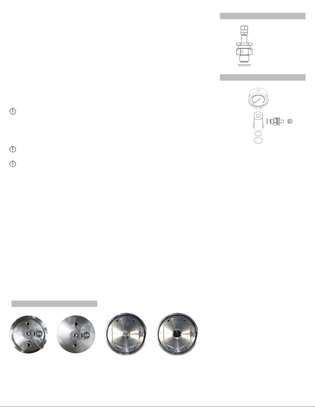
Figure 2 Gauge Adapter Assembly
Pressure Seal Check
After charging, test for Nitrogen leaks by spraying a solution of soap and water on charging
valve and cap threads. If any leaks are observed, refer to Maintenance, Inspection & Repair
section below to remove all pressure from dampener before proceeding. After all pressure
has been removed from dampener, follow steps below to determine cause of leaks and repair
before recharging. Repeat pressure seal check until no leaks observed.
1. If bubbles appear at charging valve opening, charging valve needs to be tightened. Use a
suitable wrench to turn charging valve opening nut clockwise until it is tightly closed (Figure 1).
If bubbles appear at base of charging valve, check that charging valve is properly tightened into
dampener cap. Use a 3/4” (19 mm) deep socket and torque wrench to thread charging valve
and torque to specications below based on dampener maximum allowable working pressure
(MAWP). Pressurize dampener and repeat pressure seal check. If leaks continue, proceed to
next step.
Torque Specications: 0 to 10,000 psi 23-25 ft lbs (32-34 Nm)
10,001 to 15,000 psi 30–35 ft lbs (41-47 Nm)
2. Use a 3/4” (19 mm) deep socket to remove charging valve. Inspect charging valve O-ring
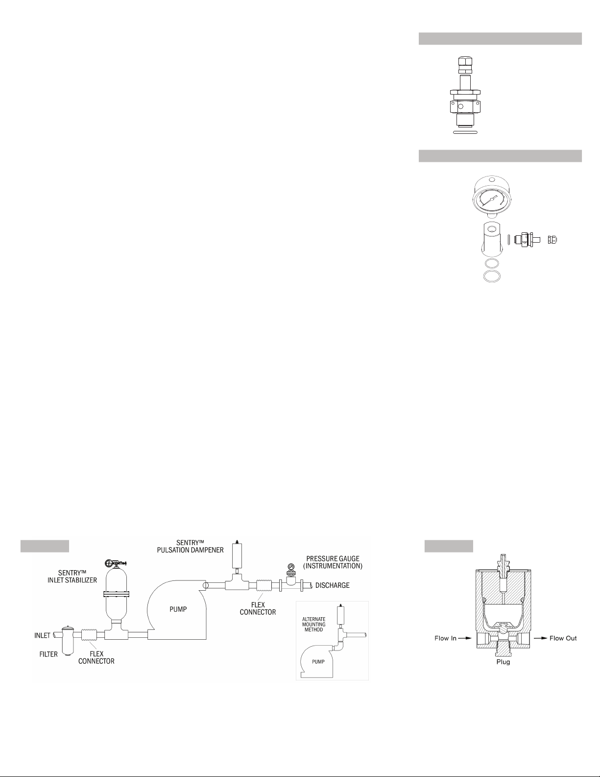
and replace if damaged. For models with optional Gauge Adapter Assembly (Figure 2), use a
suitable wrench to remove assembly tting from dampener cap. Inspect assembly O-rings and
replace if needed. Pressurize dampener and repeat pressure seal check. If leaks continue,
proceed to next step.
3. If bubbles appear around cap threaded holes, there is a problem with the bladder/bellows
seal with the cap. Refer to Maintenance, Inspection & Repair section below to disassemble
charging valve and dampener cap. Inspect and replace parts as instructed.
7BLACOH Industries
Depending on system conditions such as temperature and duty cycle, very little maintenance is required. Dampener’s pre-charge should be
checked periodically, usually every 60 to 90 days or whenever pulsation and/or vibration become more pronounced.
XP, XPH and XPX dampener models have single cap or dual hex nut caps depending on the model, and are tted with an elastomer
bladder or PTFE bellows. Refer to appropriate instructions below for the specic XP dampener model based on cap design and
ttings.
Maintenance, Inspection & Repair
Process liquid and Nitrogen may escape if bladders/bellows fail. Always wear safety glasses and other appropriate safety equipment
when disassembling dampener.
CAUTION! Extreme pressure and/or possible hazardous chemicals are involved in dampener disassembly. Only properly trained persons
can perform dampener maintenance and repair.
Disassembly
4. After all pressure has been removed from dampener, loosen safety wire bolt, untwist
safety wire to separate and remove from dampener. For dual cap models, remove safety
wire from both non-wetted and wetted caps.
5. Use a 3/4” (19 mm) deep socket to remove charging valve (Figure 1). Inspect charging
valve O-ring and replace if damaged. For models with optional Gauge Adapter Assembly
(Figure 2), use a suitable wrench to remove assembly tting from dampener cap. Inspect
assembly O-rings and replace if needed.
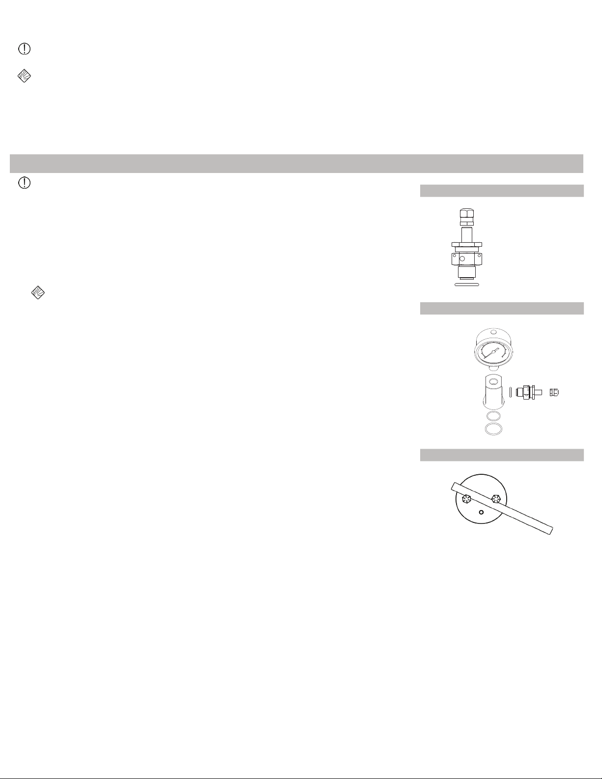
6. Remove dampener cap(s) from dampener housing. Depending on model, dampener will
have a single cap or dual hex nut caps.
Single Cap Model. Thread two 3” 5/16–18 Grade 8 bolts into threaded bolt holes in cap.
Insert rod or heavy duty screwdriver with long shank between the two bolts and remove
cap by turning counterclockwise (Figure 3).
Dual Cap Model. Use appropriate tool to remove both hex nut caps by turning
counterclockwise.
7. Inspect dampener bladder/bellows and O-rings, and replace as needed. Consult factory
for replacement parts.
1. Close isolation valve if installed or remove dampener from pumping system.
2. If the dampener is tted with eye bolts for lifting, rotate eye bolt nuts up bolt threads
slightly (away from cap). Turn bolts counterclockwise to completely remove from cap.
3. Remove all pressure from dampener before disassembly. Point dampener charging valve
in a safe direction. To verify dampener is not pressurized, remove charging valve cap
and use a suitable wrench to slowly open charging valve by turning valve opening nut
counterclockwise (Figure 1).
Nitrogen becomes extremely cold and can burn bare skin when released
under pressure. Also, ice may form and clog the charging valve which will
prevent complete pressure charge release. Wait at least one minute after all
pressure has been released before continuing with disassembly.
Pump must be turned off and system pressure must be zero prior to disassembly.
Cap
Valve Opening Nut
O-Ring
Figure 1 Charging Valve
Fitting
Charging
Valve
O-Rings
Figure 2 Gauge Adapter Assembly
Figure 3 Single Cap

8BLACOH Industries
Safety Wire Bolt
Charging Valve
Non-wetted Housing
Rubber O-Ring
Wetted Cap
PTFE Bellows
Anti-extrusion Button
PTFE Encapsulated O-Ring
Reassembly
Use caution not to cross-thread dampener cap(s) on reassembly.
Make certain all components are clean and free of corrosion before reassembly.
Safety wire must be re-installed on reassembly (see Safety Wire section below).
1. Install PTFE encapsulated O-ring onto wetted cap, making sure O-ring is seated in cap bead groove.
2. Snap anti-extrusion button into recess in center of PTFE bellows.
3. Snap PTFE bellows onto wetted cap, making sure top of bellows is touching cap lip.
4. Install rubber O-ring onto O-ring groove in PTFE bellows, making sure O-ring is seated in bellows bead groove.
5. Lubricate wetted cap threads and rubber O-ring installed on PTFE bellows with LOCTITE C-5A Copper Anti-Seize, Molykote G-n Metal
Assembly Paste or similar anti-seize compound. Apply paste sparingly by hand or with a stiff brush, rubbing paste into cap threads.
6. Spray bellows and inside of non-wetted housing with a solution of soap and water that is slippery to the touch.
7. Thread two 3” 5/16–18 Grade 8 bolts into threaded bolt holes in wetted cap (if bolts were removed on disassembly).
8. Insert cap/bellows assembly straight down into non-wetted housing, using caution not to cut or damage PTFE bellows/O-rings on housing
threads.
9. Using a rod or long shank screwdriver and the two bolts, thread wetted cap (clockwise) into non-wetted housing carefully to avoid cross-
threading (Figure 3). Cap must be tightened rmly into housing to ensure a proper seal. Remove the two bolts from wetted cap.
Single Cap PTFE Bellows Model (Figure 5)
1. Install bladder onto non-wetted cap, making sure internal bladder bead is seated in cap bead groove.
2. Lubricate non-wetted cap threads with LOCTITE C-5A Copper Anti-Seize, Molykote G-n Metal Assembly Paste or similar anti-seize
compound. Apply paste sparingly by hand or with a stiff brush, rubbing paste into cap threads.
3. Spray bladder and inside of wetted housing with a solution of soap and water that is slippery to the touch.
4. Thread two 3” 5/16-18 Grade 8 bolts into threaded bolt holes in non-wetted cap (if bolts were removed on disassembly).
5. Insert cap/bladder assembly straight down into wetted housing, using caution not to cut or damage bladder on housing threads.
6. Using a rod or long shank screwdriver and the two bolts, thread non-wetted cap (clockwise) into wetted housing carefully to avoid cross-
threading (Figure 3). Cap must be tightened rmly into housing to ensure a proper seal. Remove the two bolts from non-wetted cap.
Single Cap Elastomer Bladder Model (Figure 4)
Step 1 Housing & Cap(s)
To reassemble housing and cap(s), refer to the appropriate instructions below for the specic XP dampener model.
Safety Wire Bolt
Charging Valve
Non-wetted Cap
Elastomer Bladder
Wetted Housing
Figure 4 Single Cap Elastomer Bladder Model Figure 5 Single Cap PTFE Bellows Model
9BLACOH Industries
1. Install O-ring onto wetted cap, making sure O-ring is seated in cap bead groove.
2. Lubricate wetted cap threads with LOCTITE C-5A Copper Anti-Seize, Molykote G-n Metal Assembly Paste or similar anti-seize compound.
Apply paste sparingly by hand or with a stiff brush, rubbing paste into cap threads.
3. Thread wetted cap into housing and torque to 80 ft lbs (108 Nm) with appropriate tool.
4. Snap anti-extrusion button into recess in center of bladder (wetted side).
5. Snap bladder onto non-wetted cap, making sure bladder is rmly attached.
6. Lubricate non-wetted cap threads with LOCTITE C-5A Copper Anti-Seize, Molykote G-n Metal Assembly Paste or similar anti-seize
compound. Apply paste sparingly by hand or with a stiff brush, rubbing paste into cap threads.
7. Spray bladder and inside of housing with a solution of soap and water that is slippery to the touch.
8. Insert non-wetted cap/bladder assembly straight down into housing, using caution not to cut or damage bladder on housing threads. Thread
assembly into housing and torque to 80 ft lbs (108 Nm) with appropriate tool.
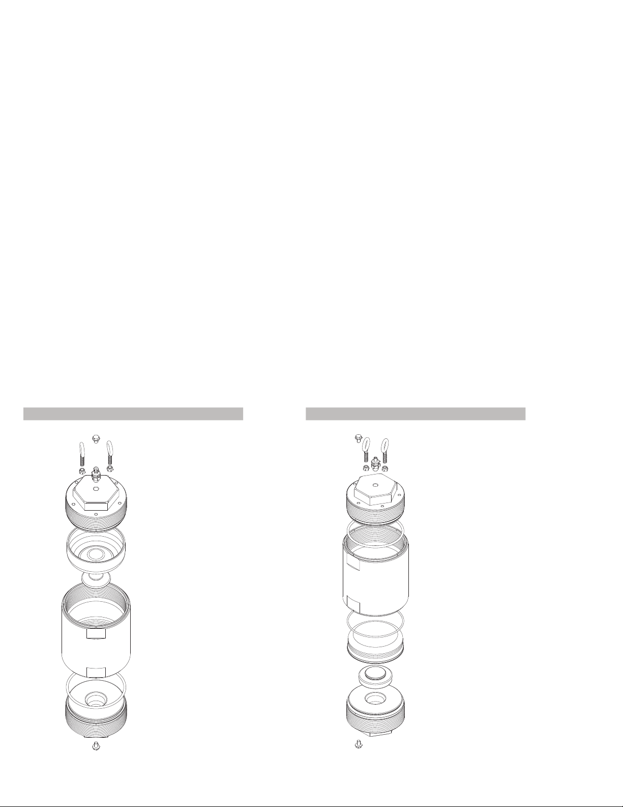
Dual Cap Elastomer Bladder Model (Figure 6)
Dual Cap PTFE Bellows Model (Figure 7)
1. Snap anti-extrusion button into recess into center of PTFE bellows (wetted side).
2. Install O-ring onto O-ring groove in PTFE bellows, making sure O-ring is seated in bellows bead groove.
3. Snap bellows onto wetted cap, making sure bellows is rmly attached.
4. Lubricate wetted cap threads with LOCTITE C-5A Copper Anti-Seize, Molykote G-n Metal Assembly Paste or similar anti-seize compound.
Apply paste sparingly by hand or with a stiff brush, rubbing paste into cap threads.
5. Spray bellows and inside of housing with a solution of soap and water that is slippery to the touch.
6. Insert wetted cap/bellows assembly straight down into housing, using caution not to cut or damage bladder on housing threads. Thread
assembly into housing and torque to 80 ft lbs (108 Nm) with appropriate tool.
7. Install O-ring onto non-wetted cap, making sure O-ring is seated in cap bead groove.
8. Lubricate non-wetted cap threads with LOCTITE C-5A Copper Anti-Seize, Molykote G-n Metal Assembly Paste or similar anti-seize
compound. Apply paste sparingly by hand or with a stiff brush, rubbing paste into cap threads.
9. Thread non-wetted cap into housing and torque to 80 ft lbs (108 Nm) with appropriate tool.
Eye Bolts
Safety Wire Bolt
Charging Valve
Non-wetted Cap
Elastomer Bladder
Anti-extrusion Button
Housing
O-Ring
Wetted Cap
Safety Wire Bolt
Figure 6 Dual Cap Elastomer Bladder Model
Eye Bolts
Safety Wire Bolt
Charging Valve
Non-wetted Cap
PTFE Bellows
Anti-extrusion Button
Housing
O-Ring
Wetted Cap
Safety Wire Bolt
O-Ring
Figure 7 Dual Cap PTFE Bellows Model
10BLACOH Industries
Step 2 Charging Valve and Optional Gauge Adapter Assembly
Inspect charging valve O-ring and replace if needed (Figure 1). Install charging valve into
dampener charging valve port or, if applicable, into Gauge Adapter Assembly tting, making sure
charging valve O-ring is properly installed. Use a 3/4” (19 mm) deep socket and torque wrench to
thread charging valve and torque to specications below based on dampener maximum allowable
working pressure (MAWP).
Torque Specications: 0 to 10,000 psi 23-25 ft lbs (32-34 Nm)
10,001 to 15,000 psi 30–35 ft lbs (41-47 Nm)
Models with Gauge Adapter Assembly. Inspect assembly O-rings and replace if needed.
Ensure tting O-rings are installed in O-ring grooves (Figure 2). Spray adapter tting O-rings with
a solution of soap and water. Install assembly into dampener charging valve port. Tighten until
ush (metal to metal) using a suitable wrench. While tightening, ensure adapter tting O-rings
remain seated in O-ring grooves.
Dual Cap Model
Wetted Cap
Dual Cap Model
Non-wetted Cap
Single Cap Model
Non-wetted Housing
Single Cap Model
Non-wetted Cap
Figure 8 Safety Wire & Bolts
Step 3 Charging & Pressure Seal Check
Dampener must be charged and pressure seal checked for Nitrogen leaks prior to
reinstalling safety wire.
Refer to Charging Instructions and Pressure Seal Check sections above to properly charge
dampener and check pressure seal before proceeding to next step.
Single Cap Model Non-wetted Cap/Housing & Dual Cap Model Non-wetted Cap
Loop safety wire through wire port in charging valve, twist loose wires together tightly and pull taut from charging valve to the wire port in housing
lip that is in the next clockwise position below cap safety bolt. (If dampener is tted with optional Gauge Adapter Assembly, pull twisted wire
from charging valve clockwise around assembly tting and then to housing lip port.) Feed one loose wire end through housing lip port and twist
remaining wire lengths together tightly. Pull twisted wire taut up to cap safety wire bolt which should be located counterclockwise above housing
lip port and wrap clockwise once around safety wire bolt.
For single cap models tted with PTFE bellows where charging valve is installed on non-wetted housing, pull twisted safety wire taut from
charging valve directly to safety wire bolt in housing.
For dual cap models with a second safety wire bolt in housing lip in lieu of a port, pull twisted wire taut from charging valve and wrap clockwise
once around safety wire bolt in cap; pull remaining length taut and wrap once around second safety wire bolt in housing lip.
Ensure no slack in full length of safety wire. Tighten safety wire bolt(s) to secure. Bend wire ends back and down so sharp ends do not protrude.
Reinstall cap eye bolts (dual cap models only).
Dual Cap Model Wetted Cap
Loop safety wire through wire port in housing lip that is in the next clockwise position below cap safety bolt. Twist loose wires together
tightly and pull taut from housing lip up to cap safety wire bolt which should be located counterclockwise above housing lip port and wrap
counterclockwise once around safety wire bolt.
For models with a second safety wire bolt in housing lip in lieu of a port, pull twisted wire taut from charging valve and wrap clockwise once
around safety wire bolt in cap. Pull remaining length taut and wrap once around second safety wire bolt in housing lip. Ensure no slack in full
length of safety wire. Tighten safety wire bolt(s) to secure. Bend wire ends back and down so sharp ends do not protrude.
Step 4 Safety Wire and Bolts, Eye Bolts
All XP high pressure dampeners are equipped with safety wire and bolts which must be
reinstalled after disassembly (Figure 8).
Eye bolts installed on dual cap models for lifting must be reinstalled after disassembly.
Cap
Valve Opening Nut
O-Ring
Figure 1 Charging Valve
Fitting
Charging
Valve
O-Rings
Figure 2 Gauge Adapter Assembly

11BLACOH Industries
XP High Pressure models are available with optional Gauge Adapter Assembly, either factory installed or purchased separately (Figure 2). When
purchased separately, Gauge Adapter Assembly includes charging valve. Follow instructions below to install optional Gauge Adapter Assembly
when purchased separately.
Gauge Adapter Assembly Installation
Pump must be turned off and system pressure must be zero prior to disassembly.
1. Close isolation valve if installed or remove dampener from pumping system.
2. If the dampener is tted with eye bolts for lifting, rotate eye bolt nuts up bolt threads
slightly (away from cap). Turn bolts counterclockwise to completely remove from cap.
3. Remove all pressure from dampener before disassembly. Point dampener charging valve
in a safe direction. To verify dampener is not pressurized, remove charging valve cap
and use a suitable wrench to slowly open charging valve by turning valve opening nut
counterclockwise (Figure 1).
4. After all pressure has been removed from dampener, loosen safety wire bolt, untwist
safety wire to separate and remove from dampener.
5. Use a 3/4” (19 mm) deep socket to remove charging valve from dampener cap and
discard.
6. Ensure gauge adapter tting O-rings are seated in O-ring grooves (Figure 2). Spray
O-rings with a solution of soap and water.
7. Install complete assembly into dampener charging valve port. Tighten until ush (metal to
metal) using a suitable wrench. While tightening, ensure tting O-rings remain seated in
O-ring grooves.
8. Refer to Charging Instructions and Pressure Seal Check sections above to properly
charge dampener and check pressure seal before proceeding to next step.
Nitrogen becomes extremely cold and can burn bare skin when released
under pressure. Also, ice may form and clog the charging valve which will
prevent complete pressure charge release. Wait at least one minute after all
pressure has been released before continuing with disassembly.
Details regarding warranty and return policy are available on Blacoh’s website at www.Blacoh.com
Manufacturer’s Limited Warranty & Return Policy
Cap
Valve Opening Nut
O-Ring
Figure 1 Charging Valve
Fitting
Charging
Valve
O-Rings
Figure 2 Gauge Adapter Assembly
9. Reinstall safety wire and bolts:
Loop safety wire through wire port in charging valve, twist loose wires together tightly and pull taut from charging valve clockwise around
assembly tting to wire port in housing lip. Feed one loose wire end through housing lip port and twist remaining wire lengths together tightly.
Pull twisted wire taut and wrap clockwise once around safety wire bolt in cap.
For single cap models tted with PTFE bellows where charging valve is installed on non-wetted housing, pull twisted safety wire taut from
charging valve directly to safety wire bolt in housing.
For dual cap models with a second safety wire bolt in housing lip in lieu of a port, pull twisted wire taut from charging valve and wrap
clockwise once around safety wire bolt in cap; pull remaining length taut and wrap once around second safety wire bolt in housing lip.
Ensure no slack in full length of safety wire. Tighten safety wire bolt(s) to secure. Bend wire ends back and down so sharp ends do not
protrude. Reinstall cap eye bolts (dual cap models only).

M28E11_093
Blacoh Headquarters − Oces Worldwide
601 Columbia Ave, Bldg D, Riverside, CA 92507 USA
951.342.3100
Blacoh.com
PROUDLY MANUFACTURED IN THE USA
Pulsation Dampeners & Surge Suppressors
High Pressure Dampeners
Inlet Stabilizers
Sanitary Dampeners
Accumulators
This manual suits for next models
2
Table of contents
Other Blacoh Industrial Equipment manuals


Popular Industrial Equipment manuals by other brands


ITALVIBRAS GIORGIO SILINGARDI
ITALVIBRAS GIORGIO SILINGARDI MVCC Series Technical handbook

FlexArm
FlexArm GH-24 Installation & operation manual

Chicago Dryer
Chicago Dryer Air Chicago Standard instruction manual

ABB
ABB TPS61-F32 Operation manual

ITC
ITC ECOFERTIC instruction manual

Wilo
Wilo SiBoost Smart Helix V Series Installation and operating instructions