Norgren VP51 User manual

Our policy is one of continuous research and development. We therefore reserve the right
to amend, without notice, the specification given in this document.
1: Supply
2: Output
3: Exhaust
P
=
A
D
VP51
Programmable Proportional Pressure Control Valve
•Air piloted Digital proportional pressure control valve
•Fully Programmable with on-board Diagnostics
•Multi-Option Language Display
•Password Protection option at first level functionality
•Instant LED warning functions
•Application specific set-up
•Pressure Output Display; No Gauge Necessary
•High Speed Response
Technical Data
Medium:
Compressed air, filtered to 50 micron, non-lubricated
Operation:
Proportional, direct acting piloted spool valve
Output Pressure:
User adjustable up to 10 bar
Max Supply pressure:
14bar max
*Response Time (into 0.1litre load):
Step response: 10-90% <100ms
Air Consumption:
<5Nl/min
Port Size:
G¼, ¼”NPT, in line
Manifold mounting
Total Error:
Max. error +/-100mbar (independent error
includes the combined effect of non-linearity, hysteresis,
deadzone and repeatability)
Operating Temperature (ambient):
-20° to 50°C
Temperature Effect:
Typically 3mbar/°C for full scale and zero over operating
range
Degree of Protection:
IP65 in normal operation
Life:
>30million 100% steps
Mounting Position:
Any (ideally vertical for display use), Screw mounting
Material of Construction:
Aluminium body, zinc diecast lid and end cover
Overall Dimensions:
131.5 x 55 x 50mm
Mass:
800g approx.
Symbol
*For continuous operation up to three 100% steps per second. For applications requiring greater continuous cyclic frequency of operation, please consult Norgren.
1 +24V d.c. supply
2 output pressure feedback signal
3 control signal (+ve)
4 common (DC supply, signal and feedback return)
5 chassis
1
2
4
5
3
Instrument pin configuration
DsVP51g_01/04

Our policy is one of continuous research and development. We therefore reserve the right
to amend, without notice, the specification given in this document.
Inputs (signal) Analogue set points
General Characteristics
10 kΩ (voltage)
220 Ω(current)
Load resistance
0-10 V / 4-20 mAControl signal
50 kΩ(voltage)
220 Ω(current)
Input resistance
<=50mbar between 11bar and
6bar supply
Supply Sensitivity
<0.3bar, 3 g sine,
10-150Hz (3 axes)
Vibration Immunity
fixedFlow Direction
5bar minimum operating
pressure
Operating Pressure
1300 l/minFlow Capacity
<1bar overshoot
10-90% <=80ms
90-10% <=120ms
100cc load
Response Sensitivity
<+/-50mbar
<0.5% of span (BSL)
Linearity
<50mbar
<0.5% of span
Hysteresis
Electrical Information
User Configurable: 0-10V
analogue or Hi-Lo mode
Output pressure
feedback signal
M12, 5 pin connector e.g.
Hirschmann 933 170-100
Connections
24Vdc ±25%
Electrical Power
input
0-10V or 4-20mA
Electrical input
signal
CE marked. Conforms to
E.C.s requirements
EN50081-2(1994) and
EN50082-2(1995). For this
standard specification
shielded cables must be
used
Electromagnetic
Compatibility

Our policy is one of continuous research and development. We therefore reserve the right
to amend, without notice, the specification given in this document.
Use Arrow Keys to scroll through language and pressure options.
Press OK to accept.
Allows user to set pressure output between 0-10 Bar for both Min
and Max demand signals.
This makes it possible to have a low signal giving a high output and
vice versa.
Scroll through numerical values
0-7 to set speed.
0 = fastest, 7= slowest
N.B Response will vary with load volume.
Min
Set up
With Air supply on, Set the input signal to the required Max and Min
values. Use the Arrow Keys to fine tune the VP51 to the host
system.
Display function that provides feedback facility for user information.
Green LED is normally permanently on when power supply is
present. This function allows user to set Green LED to flash when
output pressure is outside a specified window.
Red LED is normally off. Can be set to flash if output pressure does
not reach the required value within a specified time limit. Red LED
will also flash when running in local control functions.
Local control function enables the user to manually set output
pressure using arrow keys. To accept command press OK. This will
display an output pressure warning. To return to Remote Control
press C followed by OK. This will display the main menu structure.
Display function that shows device ID , serial No. Also contains
password change facility Web address of distributor.
Provides option to resort factory defaults.
Enter a 4 Digit password and press OK . If password is inactive
press OK to enter.
To set the proportional gain first set the integral gain to 0, then
adjust the proportional gain to give the best response time for your
application. Once set adjust integral gain to stabilise this output.
0 = low, 7 = high.
Scroll through numerical values 0-7 and press OK to accept. This
function allows the dither amplitude to be adjusted according to the
application.
0 = dither off, 7 = dither max.
Display
Language
Pressure
Units
Min
Set up
Max
Set up
Max
Set up
Speed
Setting
Prop Gain
Dither
Amp
Monitor
Output
Green On
Limits
Red On
Limits
Manual
Control
Off line
Set up
On-Line
Set up
Monitor
Set up
Local
Control
Password
Factory
Defaults
Display
Set up
Device
Database
Menu Structure / User Functionality Options
• Up and Down move between options and
set digit values within functions
• Move up and down tree
• Left and Right move between settable
digits
Arrow Keys
ÃÅÆ Ä
• Move back through levels
of the menu
• Cancel changes
• Moves left on tree
“C”
• Enter the menu from default
screen
• Move to the next level of the
menu
• Accept changes
• Move right on tree
“OK”
Keypad Functions:
Int Gain

Our policy is one of continuous research and development. We therefore reserve the right
to amend, without notice, the specification given in this document.
Part Numbering:
150 psig outlet; 0-10V control signal; ¼” NPT portsVP5110PK111H00
10 Bar outlet; 0-10V control signal; ¼” BSP portsVP5110BJ111H00
150 psig outlet; 4-20mA control signal; ¼” NPT portsVP5110PK411H00
10 Bar outlet; 4-20mA control signal; ¼” BSP portsVP5110BJ411H00
DescriptionPart Number
Accessories (Inclusive with the Unit):
M12 x 1; 5 pole
Length: 54 mm
Plug securing nut: 20 mm
Female connector piece: 8mm
Specification
Plug Connector, 5 pin, M12, female receptacle
Watson Smith Part Number: PL 500 01
(Defined as “H” in VP51 Part Number)
Ordering Information
M12 x 1; 5 pole
Height: 35 mm
Depth: 36 mm
Plug securing nut: 20 mm
Female connector piece: 8mm
Specification
Elbow Plug Connector, 90°, 5 pin, M12 female receptacle
Watson Smith Part Number: PL 500 02
(Defined as “G” in VP51 Part Number)

Our policy is one of continuous research and development. We therefore reserve the right
to amend, without notice, the specification given in this document.
Dimensional Detail:
Characteristic Curves:
Forward Flow Characteristics
(Supply Pressure 11bar)
0
1
2
3
4
5
6
7
8
9
10
0 200 400 600 800 1000 1200 1400 1600
Flow (Nl/min)
Outlet Pressure (bar)
Relief Flow Characteristics
(Supply Pressure 9 bar)
0
1
2
3
4
5
6
7
8
9
-2000 -1500 -1000 -500 0
Flow (Nl/m in)
Outlet Pressure (bar)
1: Inlet Port
2: Outlet Port
3: Exhaust Port

Our policy is one of continuous research and development. We therefore reserve the right
to amend, without notice, the specification given in this document.
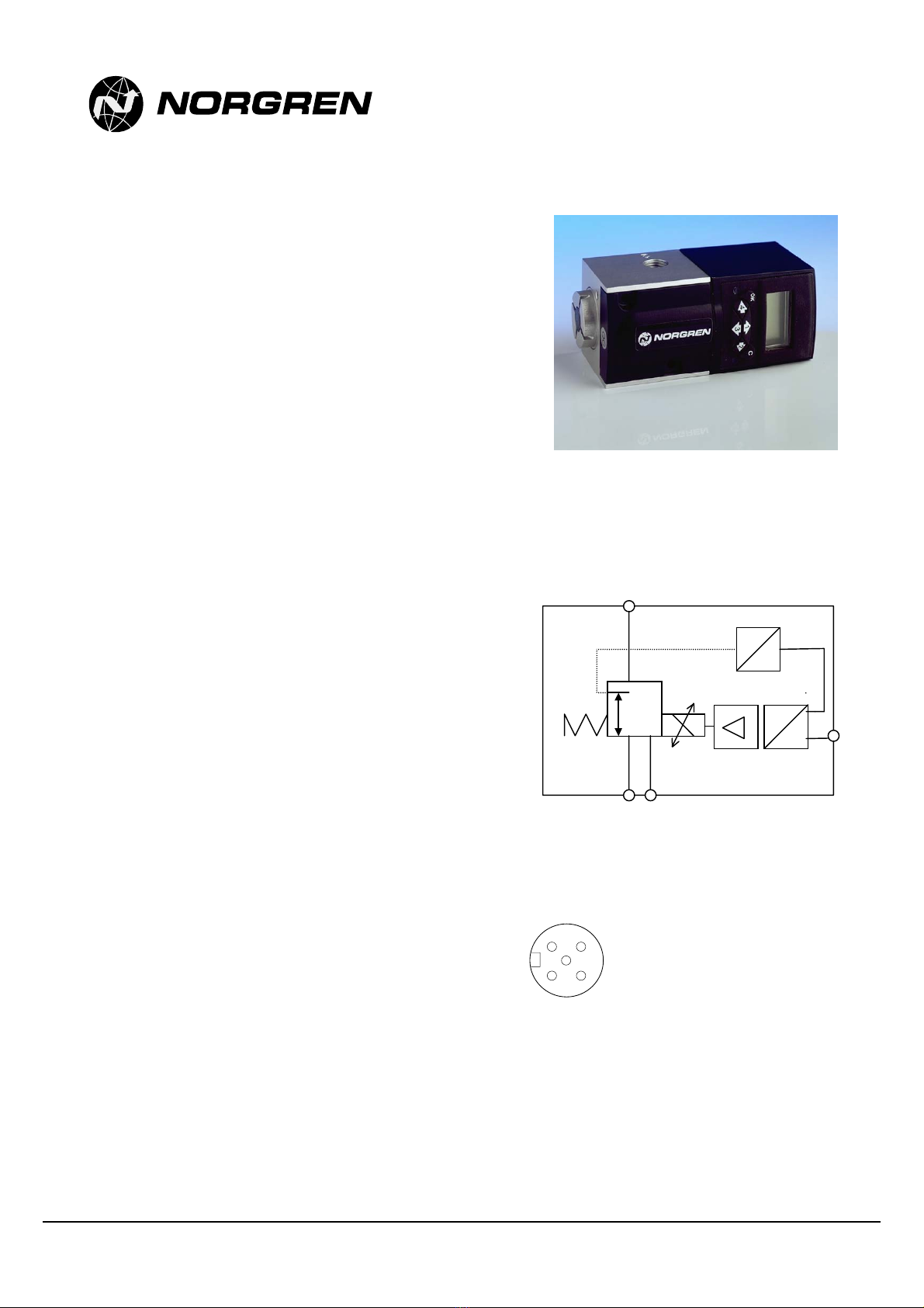
Installation and Commissioning
Pneumatic Installation
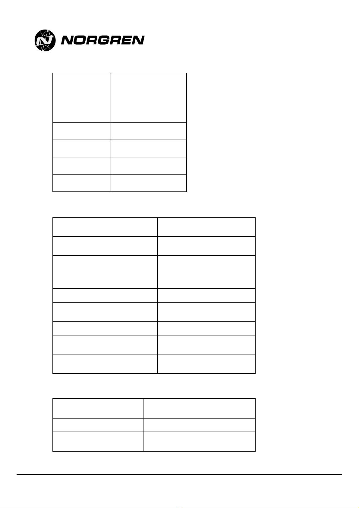
Supply Pressure:
Minimum 1 bar (14.5psig) above maximum
required output pressure for function (11 bar
(203psig) max.)
Output Pressure Range:
0-10 bar (0-145psig)
Media:
Clean, dry 5 micron filtered air
Port Size:
G ¼; ¼”NPT
Connection:
Pipe-work connection using 10mm OD, 8mm
ID, plastic pipe, cut cleanly at right angles, with
push-fit pipe connections.
Exhaust silencer at Port 3 if required (this will
only slightly degrade exhaust performance).
The connector plug must be hand-tight only, to
a tightening force less than 3 Newton.
Mounting:
Any mounting orientation.
Screw mounting through body mounting holes
to suit M4 screws.
Adjustment Controls:
Various via user interface.
Electrical installation
Power Supply:
24V dc power supply (+/- 25% with 250mA
current capability)
Signal:
0-10V, 4-20mA
Feedback:
10V full scale; switch mode settable
Connection:
5-core, screened cable and M12 socket
connector
Servicing and Repairs
A two year warranty applies to all Norgren products.
For terms and conditions please ask for a copy of
our ‘General Conditions of Sale.’
You should by no means attempt to repair the
product by yourself.
For repair please return the product concerned with
a description of the error, malfunction or failure to
the following address:
IMI Watson Smith Limited
Cross Chancellor Street
Leeds
LS6 2RT
U.K.
or contact us on:
Tel.: +44 (0)1132457587
Fax.: +44 (0)1132465735
E-mail: enquiries@watsonsmith.com
Website: http://www.watsonsmith.com
Transport, Storage and Cleaning
The product can only be transported and stored in
the original Norgren and Watson Smith packaging
which ensures suitable protection against
mechanical damage.
In case it is necessary to clean the product, we
recommend sending it back to the manufacturer.
The correct address can be found under servicing
and repairs.
Warning
These products are intended for use in industrial compressed air systems only. Do not use these products where pressures and
temperatures can exceed those listed under ‘Technical Data’.
Before using these products with fluids other than those specified, for non-industrial applications, life-support systems, or other applications
not within published specifications, consult NORGREN.
Through misuse, age, or malfunction, components used in fluid power systems can fail in various modes. The system designer is warned to
consider the failure modes of all component parts used in fluid power systems and to provide adequate safeguards to prevent personal
injury or damage to equipment in the event of such failure.
System designers must provide a warning to end users in the system instructional manual if protection against a failure mode
cannot be adequately provided.
System designers and end users are cautioned to review specific warnings found in instruction sheets packed and shipped with these
products.
This manual suits for next models
4
Table of contents
Other Norgren Control Unit manuals

Norgren
Norgren FD67 User manual

Norgren
Norgren VR10 Installation and operating instructions

Norgren
Norgren 82 Series User manual

Norgren
Norgren VP23 Series User manual

Norgren
Norgren VR10 Instruction Manual

Norgren
Norgren VP60 Series User manual

Norgren
Norgren Prospector A00 5A Series User manual

Norgren
Norgren HERION G1/4 User manual

Norgren
Norgren VS18 Manual