BLB hydraulic BM70 User manual

BM70
MONOBLOCK
DIRECTIONAL
CONTROL
VALVES
INSTRUCTIONS MANUAL
UPGRADE YOUR HYDRAULIC CONTROL
BM70 MONOBLOCK DIRECTIONAL CONTROL VALVES | INSTRUCTIONS MANUAL2
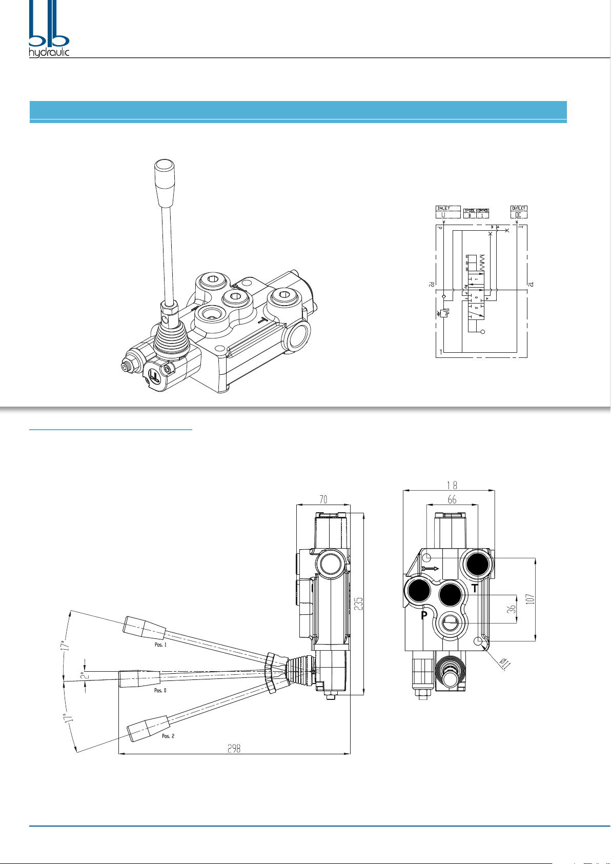
ITEM 86503009 / 92811001 BM70/1 ZB GU P/MO B1/T TAR5
BM70/1 installation dimensions
3
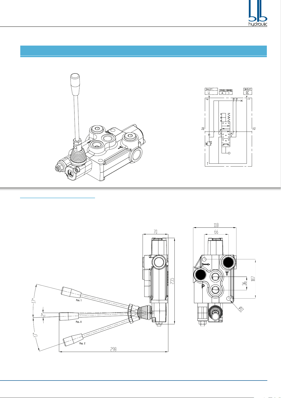
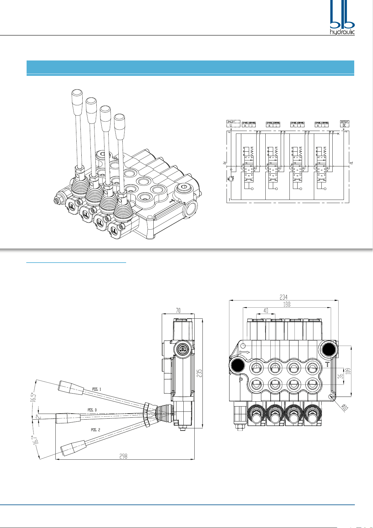
ITEM 86503010 / 92811005 BM70/1 ZB GU P/MO A1/T TAR5
BM70/1 installation dimensions
BM70 MONOBLOCK DIRECTIONAL CONTROL VALVES | INSTRUCTIONS MANUAL

BM70 MONOBLOCK DIRECTIONAL CONTROL VALVES | INSTRUCTIONS MANUAL4
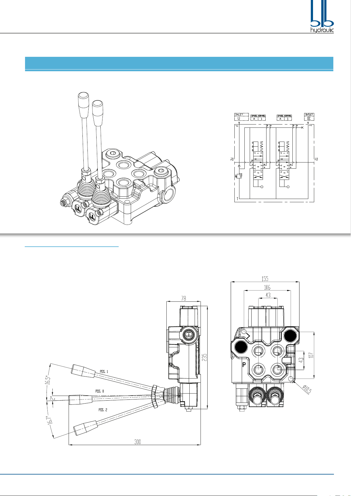
ITEM 86503011 / 93811002 BM70/2 ZB GU P/MO B1/MO B1/T TAR5
BM70/2 installation dimensions
BM70 MONOBLOCK DIRECTIONAL CONTROL VALVES | INSTRUCTIONS MANUAL 5
ITEM 86503012 / 93811012 BM70/2 ZB GU P/MO A1/MO A1/T TAR5
BM70/2 installation dimensions
BM70 MONOBLOCK DIRECTIONAL CONTROL VALVES | INSTRUCTIONS MANUAL6
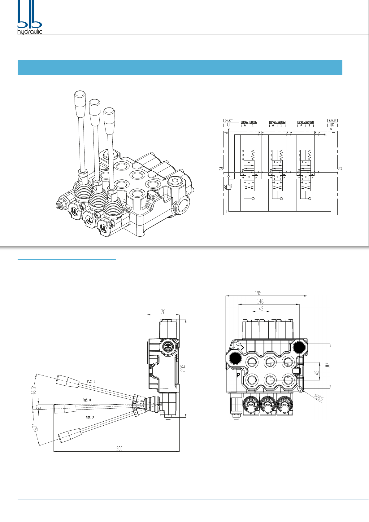
ITEM 86503013 / 93811013 BM70/3 ZB GU P/MO A1/MO A1/MO A1/T TAR5
BM70/3 installation dimensions
BM70 MONOBLOCK DIRECTIONAL CONTROL VALVES | INSTRUCTIONS MANUAL 7
ITEM 86503014 / 92811006 BM70/4 ZB GU P/MO A1/MO A1/MO A1/MO A1/T TAR5
BM70/4 installation dimensions

BM70 MONOBLOCK DIRECTIONAL CONTROL VALVES | INSTRUCTIONS MANUAL8
ITEM 86503015 / 92811007 BM70/5 ZB GU P/MO A1/MO A1/MO A1/MO A1/MO A1/T TAR5
BM70/5 installation dimensions
BM70 MONOBLOCK DIRECTIONAL CONTROL VALVES | INSTRUCTIONS MANUAL 9
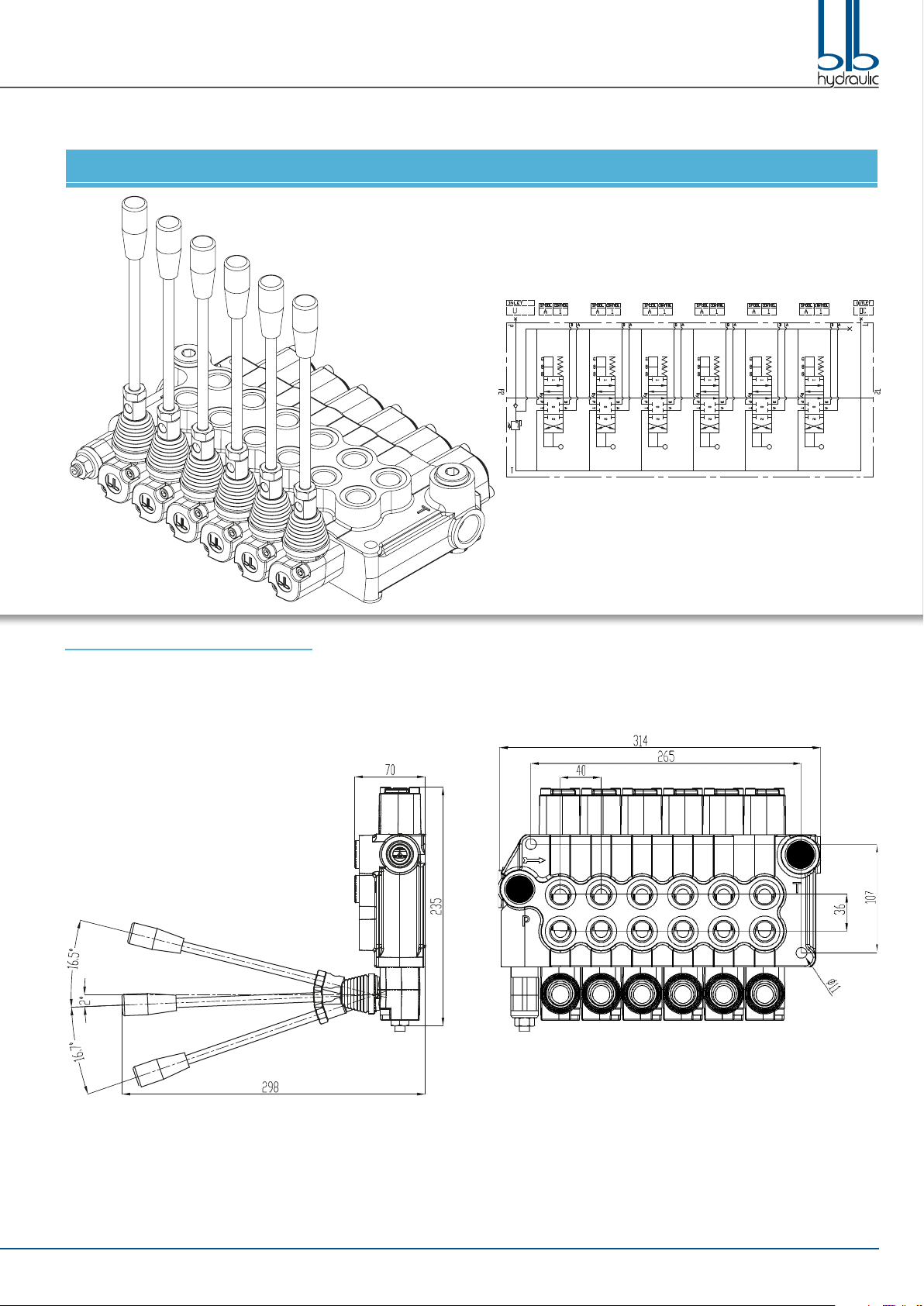
ITEM 86503016/ 92811002 BM70/6 ZB GU P/MO A1/MO A1/MO A1/MO A1/MO A1/MO A1/T TAR5
BM70/6 installation dimensions

BM70 MONOBLOCK DIRECTIONAL CONTROL VALVES | INSTRUCTIONS MANUAL10
PRESSURE DROP
TECHNICAL SPECIFICATIONS
Work Flow / Max Flow 70 l/min / 80 l/min
Relief valve setting 140 bar
Relief valve range 100 to 250 bar
Inlet/Outlet Ports 3/4" G Side / 1/2” G Top
Work Ports 1/2” G
MAIN FEATURES
Zinc plating protects against corrosion and rust
Precise ow metering to accurately control actuator speed
Power beyond capability for easy addition of valves downstream
Easy to convert from Open to Closed center
Customizable with a variety of spool and positioner options
BM70 MONOBLOCK DIRECTIONAL CONTROL VALVES | INSTRUCTIONS MANUAL 11
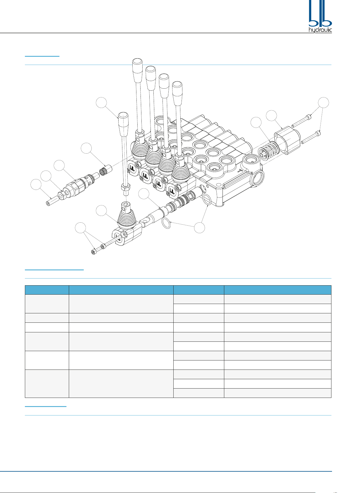
PARTS LIST:
Drawing 1
BM70 SPARE PARTS
Nº PARTS PARTS Nº SUB PART SUB PART
1Relief Valve kit 1.1 Adjusting Screw
1.2 Nut
2Check valve
3Kit handle
4Handle cap kit 4Handle Cap
4.1 Screw
5Spool kit 5.1 O-ring Seal
5Spool
6Spool Control kit
6Spool Control Cap
6.1 Spool Control kit
6.2 Screw
INSTALLATION
The installation of the valve calls for tightening of screws, ttings and hoses. Proper force must be used for the tightening of each element, in order
to prevent functional problems: excessive tightening might cause deformation to the valve and compromise the correct operation of the same; weak
tightening may effect functionality and safety. Refer to the below table to determine correct torque for each element.
Never us provisional extension nor act with bumps on the wrenches.
1
1.2
1.1
2
3
4
4.1
5
5.1
6.1
6.2
6
BM70 MONOBLOCK DIRECTIONAL CONTROL VALVES | INSTRUCTIONS MANUAL12
Before installing the product, check that it has not been
damaged during internal transport.
Step 1. Install the valve in shock and vibration free areas. While moving the valve do not cause accidental bumps or shocks. The valve must be
secured with M10 screws. Apply thread-lock accessories. Mounting position is irrelevant as long as the valve is resting on a rigid and
perfectly at surface; this is necessary so that the tightening of the screws does not cause harmful deformation.
Step 2. Use hoses and ttings suitable for indicated max ow and pressure. It is strictly prohibited the usage of conic ttings and the reversal of
connections between inlet (P, P2) and tank (T, T2) lines. Remove the protective plugs from the valve ports just before connecting the hoses
to prevent contamination of the circuit with dust or other materials. Do not use wrapped on threads to seal. Tighten ttings with the torque
indicated in the table.
Step 3. Before starting, ux oil from an auxiliary system. Start the system and then operate the actuators individually and not under load. Operate
slowly until the system is lled with oil. Set the relief valve and carry out a complete test of the system. Do not perform calibration of valves
without having rst applied a pressure gauge on the inlet section of the valve and on line where deemed necessary.
CHANGING THE VALVE SPOOL AND SEALS (See drawing 1):
Step 1. Remove the Handle (Part 3).
Step 2. Remove the Screws (Part 6.2) with a 5 mm hex key and remove the Spool Control Cap (Part 6).
Step 3. Using a 5 mm hex key remove the Spool Control Kit (Part 6.1).
Step 4. Remove the Screws (Part 4.1) with a 5 mm hex key and remove the Handle Cap (Part 4).
Step 5. Always start on the Spool Control Cap side when removing the O-rings Seals. Move the Spool (Part 5) only far enough to expose the O-ring
Seals (Part 5.1). Be careful not to push the Spool too far past the O-ring Seal groove as this will cut the O-ring Seal on the Handle Cap side.
Remove the O-ring Seal with a pick.
Step 6. Remove the Spool through the Spool Control Cap end of the valve. Remove the Handle Cap side O-ring Seal with a pick.
Step 7. Lightly oil the new Spool with clean hydraulic uid. Insert the Spool into the valve and push and pull it within the valve casting to make sure
there is very little resistance. If resistance is felt please try a new Spool to eliminate binding.
Step 8. Push the Spool back on the Handle Cap end, so the O-ring Seal can be installed in the groove.
Step 9. After the O-ring Seal is installed in the Handle Cap end, slowly push the Spool from the Spool Control Cap end to expose the O-ring Seal
groove. Be careful not to push the Spool too far past the O-ring Seal groove as this will cut the O-ring Seal on the Handle Cap side. Install
the O-ring Seal in the groove.
Step 10. Install the Handle Cap rst and tighten the Screws to 8,5 Nm.
Step 11. Install the Spool Control onto the spool and tighten to 16 Nm, then install the Spool Control Cap and tighten the Screws to 8,5 Nm.
Step 12. Add the Handle to the valve and move it back and forth to feel any eventual sticking of the Spool. If it feels sticking, loose the Caps and
realign, then try again, this will x the sticking issue.
If it is not sticking the installation is complete.
CHANGING THE SPOOL CONTROL FROM SPRING CENTERED TO DETENT (See drawing 1):
Step 1. Remove the Screws (Part 6.2) with a 5 mm hex key and remove the Spool Control Cap (Part 6).
Step 2. Using a 5 mm hex key remove the old Spool Control (Part 6.1).
Step 3. Install the new Spool Control onto the Spool and tighten to 16 Nm.
Step 4. Install the Spool Control Cap and tighten the Screws to 8,5 Nm.
SETTING THE RELIEF VALVE (See drawing 1):
An adjustable relief valve is standard on all monoblock directional valves. Standard factory setting is 140 bar.
The relief pressure is adjusted by releasing the Nut (Part 1.2), and turning the Adjusting Screw (Part 1.1) with a 4 mm hex key wrench. Turning the
Adjusting Screw clockwise will increase the pressure, and counter-clockwise will decrease the pressure (a pressure gauge must be installed in the
inlet line whenever the relief valve pressure is adjusted). Adjustable pressure range is 100 bar to 250 bar.
Do not backout the Adjusting Screw to the point it falls out.
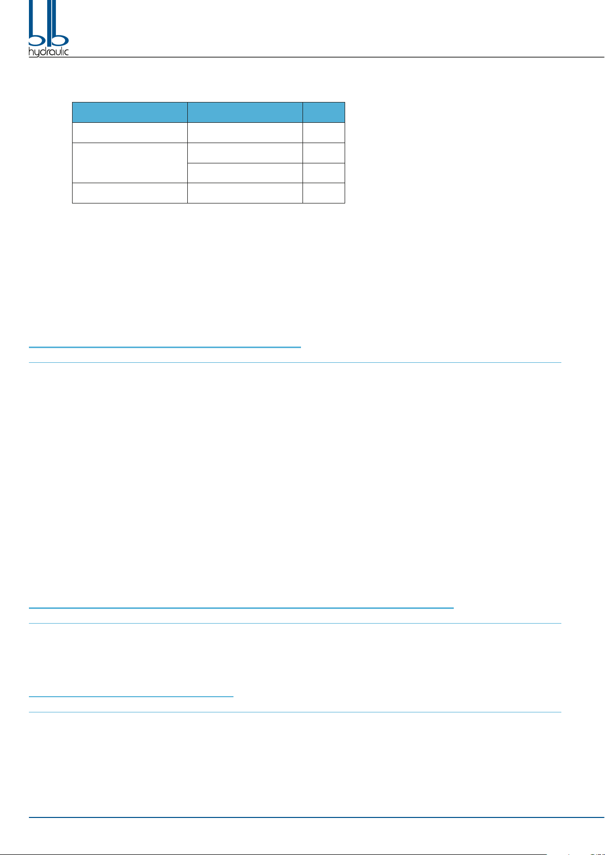
COMPONENT THREAD Nm
Fixing Screws M10 45
Connectors,
Plugs
1/2” G; 7/8”-14 UNF 55
3/4” G; 1”1/16”-12 UNF 100
Relief Valve, RVP M24 x 1,5 80

BM70 MONOBLOCK DIRECTIONAL CONTROL VALVES | INSTRUCTIONS MANUAL 13
OPTIONAL
Carry Over - CO (Power Beyond Adapter)
Closed Center Plug - CCP
Relief Valve Plug - RVP
A
A
T2
A
A
T2
14 BM70 MONOBLOCK DIRECTIONAL CONTROL VALVES | INSTRUCTIONS MANUAL
HOW TO INSTALL CARRY OVER - CO (POWER BEYOND ADAPTER)
Step 1. Screw the Power Beyond Adapter into the T2 port with 27 mm hex wrench and tighten to 45 Nm.
When the Power Beyond Adapter is installed a hose must be attached to the T port and run back to the tank.
Failure to do this will cause the valve not to function properly.
HOW TO INSTALL CLOSED CENTER PLUG - CCP
Step 1. Screw the Closed Center Plug into the T2 port with 10 mm hex key and tighten to 45 Nm.
When the Closed Center Plug is installed a hose must be attached to the T port and run back to the tank.
Failure to do this will cause the valve not to function properly.
HOW TO INSTALL RELIEF VALVE PLUG - RVP
Step 1. Remove the Relief Valve (Part 1) with a 22 mm wrench.
Step 2. Take out the Check Valve (Part 2) and install on the Relief Valve Plug.
Step 3. Screw the Relief Valve Plug into the Relief Valve port with 8 mm hex key and tighten to 45 Nm.
WARNING
All hydraulic valves must be properly installed into the hydraulic system to prevent personal injury and/or property damage. Further, the
improper servicing of a valve may result in personal injury and/or property damage. Please read and understand all catalogue and service
information before starting. As with all mechanical work, the proper tools, knowledge, and safety equipment are required. Always wear
safety disposals.
Make sure all pressure has been relieved in the hydraulic lines before installing or servicing a hydraulic valve.
Escaping hydraulic uid under pressure can have sufcient force to penetrate skin, causing serious personal injury. Do not use your hand
to check for hydraulic leaks.
Before installing or servicing a hydraulic component make sure all weight has been removed from the cylinders or motors before
disconnecting hydraulic lines.
Disconnecting the hydraulic lines while the cylinder or motor is under load may result in the unexpected rapid movement of machine
resulting in serious personal injury.
Do not exceed the operating specications for pressure, ow or temperature. All hydraulic systems need to have a maximum pressure set;
to do this, it is necessary to have either a pressure relief valve in the system or a pump that has pressure compensation.
Overpressure may cause sudden and unexpected failure of a component in the hydraulic system resulting in serious personal injury.
Always use a gauge when adjusting a relief valve.

15BM70 MONOBLOCK DIRECTIONAL CONTROL VALVES | INSTRUCTIONS MANUAL

Quality management system certied according to ISO 9001:
2008 Certicate Nr 50 100 11533
BLB S.r.l. Via Natta, 1
36040 Brendola (VI) - Italy
T. +39 0444 401141
W. www.blbhydraulic.com
MNL/GB BM70 February 2018 - © BLB Srl - All rights reserved
Other manuals for BM70
1
Table of contents
Other BLB hydraulic Control Unit manuals


Popular Control Unit manuals by other brands

Humminbird
Humminbird SOLIX Operation manual

NXP Semiconductors
NXP Semiconductors i.MX8 QM Developer's guide

KLINGER
KLINGER INTEC K210-FS Assembly and Repair Instructions

Honeywell
Honeywell Silent Knight SK-Relay-6 Installation and maintenance instructions

AV-GAD
AV-GAD AVG064 Installation and operation manual

Honeywell
Honeywell AlarmNet 7847i-E Installation and setup guide


