BLIIoT BL301 User manual

Embedded ARM Computer
BL301 BL302
BL301/302
User Manual
Version: V1.1
Date: 2023-2-28
Shenzhen Beilai Technology Co.,Ltd
Website: https://www.bliiot.com

Page 2of 45 Pages Shenzhen Beilai Technology Co., Ltd.
V1.1
https://www.bliiot.com
Embedded ARM Computer BL301 BL302
Preface
Thanks for choosing BLIIoT Embedded ARM Computer BL301 BL302. These operating instructions
contain all the information you need for operation of a device in the EdgeCOM BL30 family.
Copyright
This user manual is owned by Shenzhen Beilai Technology Co., Ltd. No one is authorized to copy,
distribute or forward any part of this document without written approval of Shenzhen Beilai
Technology. Any violation will be subject to legal liability.
Disclaimer
This document is designed for assisting user to better understand the device. As the described
device is under continuous improvement, this manual may be updated or revised from time to time
without prior notice. Please follow the instructions in the manual. Any damages caused by wrong
operation will be beyond warranty.
Revision History
Revision Date
Version
Description
Owner
December 27, 2022
V1.0
Initial Release
LKY
February 28, 2023
V1.1
Add Login instructions
LKY

Page 3of 45 Pages Shenzhen Beilai Technology Co., Ltd.
V1.1
https://www.bliiot.com
Embedded ARM Computer BL301 BL302
Table of Contents
1 Introduction................................................................................................................................................ 5
1.1 Overview.............................................................................................................................................5
1.2 Features..............................................................................................................................................5
1.3 Application scenarios........................................................................................................................ 5
1.4 Technical Specifications................................................................................................................... 6
1.5 Model Selection................................................................................................................................. 8
2 Development............................................................................................................................................. 9
2.1 Development Environment.............................................................................................................. 9
2.2 System Programming....................................................................................................................... 9
2.2.1 Programming via SD card...................................................................................................... 10
2.2.2 Programming via OTG............................................................................................................ 14
3 Hardware Specifications........................................................................................................................16
3.1 Power Interface................................................................................................................................16
3.2 LED Indicators................................................................................................................................. 17
3.3 RS485&RS232 Serial Port.............................................................................................................17
3.4 CAN Interface.................................................................................................................................. 20
3.5 PWM Interface................................................................................................................................. 22
3.6 DI........................................................................................................................................................23
3.7 LAN....................................................................................................................................................24
3.8 WiFi Module..................................................................................................................................... 27
3.8.1 STA Mode..................................................................................................................................27
3.8.2 AP Mode .................................................................................................................................... 28
3.9 4G/5G................................................................................................................................................29
3.10 USB Port.........................................................................................................................................32
3.11 Debug..............................................................................................................................................33
3.12 SD Card slot...................................................................................................................................33
3.13 SIM Card Slot................................................................................................................................ 34
3.14 Antenna Interface.......................................................................................................................... 35

Page 4of 45 Pages Shenzhen Beilai Technology Co., Ltd.
V1.1
https://www.bliiot.com
Embedded ARM Computer BL301 BL302
3.15 Reset Button.................................................................................................................................. 35
3.16 HDMI............................................................................................................................................... 36
4 Software................................................................................................................................................... 36
4.1 Login..................................................................................................................................................36
4.2 Time Setting..................................................................................................................................... 38
4.3 MCU Frequency Modulation..........................................................................................................38
4.4 Temperature Control....................................................................................................................... 39
4.5 Wake From Sleep............................................................................................................................39
4.6 Node-Red......................................................................................................................................... 40
4.7 SQLite............................................................................................................................................... 41
4.8 Python............................................................................................................................................... 42
4.9 QT...................................................................................................................................................... 43
4.10 MySQL............................................................................................................................................ 44
4.11 Debian.............................................................................................................................................44
4.12 Ubuntu............................................................................................................................................ 44
5 Firmware update.....................................................................................................................................45
6 Warranty Terms...................................................................................................................................... 45
7 Technical Support...................................................................................................................................45

Page 5of 45 Pages Shenzhen Beilai Technology Co., Ltd.
V1.1
https://www.bliiot.com
Embedded ARM Computer BL301 BL302
1 Introduction
1.1 Overview
The BL301/BL302 series Embedded ARM Computer use NXP I.MX6ULL processor, with advanced
ARM Cortex-A7 architecture, running speed up to 800MHz. BL302 comes with 4 RS485 or RS232, 1
CAN port, 2 Ethernet ports, 2 DI, 2 PWM output and 1 USB port, 1 power input/output port, 1 HDMI, 1
Mini PCIe expansion slot for a wireless module. The computer supports LINUX, Ubuntu, Debian and
other OS; Node-Red, QT, Python, C++; MySQL, InfluxDB, SQLite and other databases. This tiny
embedded computer is widely applicable to a variety of industrial solutions.
1.2 Features
NXP I.MX6ULL processor, ARM Cortex-A7 architecture
Dual 10/100 Mbps Ethernet ports; RS485 or RS232 serial ports
1 Mini PCIe expansion slot for 4G/5G/WiFi module
Supports LINUX, Ubuntu, Debian; Node-Red, QT, Python, C++; MySQL, InfluxDB, SQLite
Automatic frequency reduction or restart when the chip is overheated
Chip frequency can be adjusted manually
Multiple sleep modes, with timing wake-up function
IP30 protection; metal shell and system are safely isolated; DIN rail installation
1.3 Application scenarios
BL301/BL302 series Embedded ARM Computer are widely applicable to IoT, Industrial IoT, digital
factories, industrial automation, energy monitoring, smart security, rail transit, telecommunications,
smart EV charging, human-computer interaction and other fields.

Page 6of 45 Pages Shenzhen Beilai Technology Co., Ltd.
V1.1
https://www.bliiot.com
Embedded ARM Computer BL301 BL302
1.4 Technical Specifications
Item
Parameter
Description
System
Processor
i.MX6ULL 800MHz
RAM
256/512MB
Flash
256MB/8GeMMC
Power
Input Voltage
DC 9~36V
Power
Consumption
Normal: 170mA@12V, max 340mA@12V
Wiring
Anti- Inverse Connection Protection
Ethernet Port
Interface Spec
2 x RJ45, 10/100Mbps, adaptive MDI/MDIX
Protection
ESD ±16kV (contact), ±18kV (air),
EFT 40A (5/50ns),
Lightening 6A (8/20µs)
Serial Port
QTY
4 x RS485/ RS232
Baud Rate
300bps-115200bps
Data Bit
7, 8
Parity Bit
None, Even, Odd
Stop Bit
1, 2
Protection
ESD ±8kV (contact), ±15kV (air)
EFT 2KV, 40A (5/50ns)
CAN Port
QTY
1
MAX Speed
1Mbps
SIM Card
QTY
2 SIM Card Slot
Spec
Drawer type slot, support 1.8V/3V SIM/UIM card (NANO)
Protection
Built-in 15KV ESD Protection
Digital Input
QTY
2
Input Type
Both Dry contact and Wet contact(NPN)
Dry Contact
Close: Short circuit
Open: Open circuit
Wet Contact
Logic 0: 0-3VDC
Logic 1: 3-30VDC
Isolation
protection
2KVrms
Digital Output
QTY
2
Output Type
PWM

Page 7of 45 Pages Shenzhen Beilai Technology Co., Ltd.
V1.1
https://www.bliiot.com
Embedded ARM Computer BL301 BL302
USB Port
QTY
1xmicro USB, 1x USB2.0
Protection
Over Current Protection
SD Card Slot
QTY
1
Spec
Supports SD, SDHC and SDXC (UHS-I) cards
HDMI
QTY
1
Antenna
QTY
1x Cellular antenna, 1xWiFi Antenna
Type
SMA Hole Type
4G Module
(Optional)
L-E version
GSM/EDGE:900,1800MHz
WCDMA:B1,B5,B8
FDD-LTE:B1,B3,B5,B7,B8,B20
TDD-LTE:B38,B40,B41
L-CE version
GSM/EDGE:900,1800MHz
WCDMA:B1,B8
TD-SCDMA:B34,B39
FDD-LTE:B1,B3,B8
TDD-LTE:B38,B39,B40,B41
L-A version
WCDMA:B2,B4,B5
FDD-LTE:B2,B4,B12
L-AU version
GSM/EDGE:850,900,1800MHz
WCDMA:B1,B2,B5,B8
FDD-LTE:B1,B3,B4,B5,B7,B8,B28
TDD-LTE:B40
L-AF version
WCDMA:B2,B4,B5
FDD-LTE:B2,B4,B5,B12,B13,B14,B66,B71
CAT-1 version
GSM:900,1800
FDD-LTE:B1,B3,B5,B8
TDD-LTE:B34,B38,B39,B40,B41
5G Module
(Optional)
Interface
PCIe
5G NR
n1/n28/n41/n77/n78/n79
LTE-FDD
B1/B3/B5/B8
LTE-TDD
B34/B38/B39/B40/B41
WCDMA
B1/B5/B8
WiFi(Optional)
Interface
PCIe
Protocol
IEEE 802.11b/g/n
Mode
STA, AP
Frequency
2.4GHz
Channel
Ch1 ~ Ch13
Security
Open, WPA, WPA2

Page 8of 45 Pages Shenzhen Beilai Technology Co., Ltd.
V1.1
https://www.bliiot.com
Embedded ARM Computer BL301 BL302
Encryption
AES, TKIP, TKIPAES
Connection
8(Max)
Speed Rate
150Mbps(Max)
Transmission
distance
Outdoor/Open area, up to 20 meters
SSID
Support
Indicator
QTY
LEDx8
Safety Certification
MTBF
≥100,000 hours
EMC
EN 55022: 2006/A1: 2007 (CE &RE) Class B
IEC 61000-4-2 (ESD) Level 4
IEC 61000-4-3 (RS) Level 4
IEC 61000-4-4 (EFT) Level 4
IEC 61000-4-5 (Surge)Level 3
IEC 61000-4-6 (CS)Level 4
IEC 61000-4-8 (M/S) Level 4
Other
CE, FCC
Environment
Working
-40~80℃, 5~95% RH
Storage
-40~85℃,5~95% RH
Others
Case
Metal Case
Size
BL302: 81mm×45mm×93mm(L*W*H)
BL301: 81mm×30mm×93mm(L*W*H)
Protection
IP30
Mounting
DIN-Rail Mounting
1.5 Model Selection
Model
BL301
BL301T
BL302
BL302T
Feature
Without DI DO MINIPCIE
With DI DO MINIPCIE
Processor
i.MX6ULL
i.MX6ULL
i.MX6ULL
i.MX6ULL
CPU Frequency
800MHz
800MHz
800MHz
800MHz
RAM
512MB
256MB
512MB
256MB
Flash
8G eMMC
256MB
8G eMMC
256MB
ETH
2 x 100M
2x 100M
2 x 100M
2x 100M
USB
1
1
1
1

Page 9of 45 Pages Shenzhen Beilai Technology Co., Ltd.
V1.1
https://www.bliiot.com
Embedded ARM Computer BL301 BL302
RS232/RS485
2
2
4
4
CAN
x
x
1
1
SD slot
1
1
1
1
MINI-PCIe
x
x
1
1
4G(GPS)/WIFI(BLE)
x
x
√
√
SIM slot
x
x
2
2
HDMI
1
1
1
1
Audio
x
x
x
x
DI
x
x
2
2
DO
x
x
2
2
House
Metal
Metal
Metal
Metal
Temperature(°C)
-25~85
-40~85
-25~85
-40~85
2 Development
2.1 Development Environment
Operating System: Ubuntu20.04 64-bit
Cross Toolchain: arm-linux-gnueabihf-gcc 4.9.0
Bootloader version: u-boot-2016.03
Linux kernel version: Linux-4.1.15
Migrate QT version: QT5.6.2
2.2 System Programming
The computer supports USB OTG and SD card programming, supports eMMC startup, and uses DIP
switch (S1) to distinguish different operation methods (NAND startup as shown in the figure below)

Page 10 of 45 Pages Shenzhen Beilai Technology Co., Ltd.
V1.1
https://www.bliiot.com
Embedded ARM Computer BL301 BL302
Mode
Switch
1
2
3
4
5
6
7
8
SD Card
Programming
OFF
OFF
ON
OFF
ON
OFF
OFF
ON
NAND startup
OFF
OFF
OFF
ON
ON
OFF
OFF
ON
USB OTG
Programming
ON
ON
OFF
OFF
OFF
OFF
OFF
OFF
eMMC startup
OFF
OFF
ON
OFF
OFF
OFF
OFF
OFF
2.2.1 Programming via SD card
Copy nand-burnsd to any directory of the Ubuntu system, such as /home/beilai/work
User profile\Linux\ programming tools\emmc-sdburn.tar.bz2 is the 4G/8G eMMC file system
1) Format the SD card into FAT32 format before using the SD card.
2) After decompressing emmc-sdburn.tar.bz2, copy it to any directory under the ubuntu system. For
example, /home/beilai/work.
3) Use a USB card reader to insert the SD card into the USB port of the computer (For VMware
virtual machine users, if the USB flash drive is not recognized by the virtual machine, you can use the
arrow pointing icon to connect the USB flash drive to the virtual machine).

Page 11 of 45 Pages Shenzhen Beilai Technology Co., Ltd.
V1.1
https://www.bliiot.com
Embedded ARM Computer BL301 BL302
4) After the virtual machine recognizes the SD card, and the directory pop up, and then perform the
following programming operation. Enter /home/beilai/work/emmc-burnsd directory, execute the script:
After executing the above command, the terminal will list the computer’s hard disk or U disk, and
choose your SD card, enter.
Note: To determine whether your U disk is sda/sdb/sdc, it can be judged according to the capacity, for
example, if the capacity of your USB flash drive is 8G, its size is 7761920 KB≈8G. Please do not
insert multiple USB flash drives at the same time to avoid confusion.
Here is an example:
###############################################################################
This script will create a bootable SD card from custom or pre-built binaries.
The script must be run with root permissions and from the bin directory of
the SDK
Example:
$ sudo ./6ullsdburn.sh
Formatting can be skipped if the SD card is already formatted and
partitioned properly.
###############################################################################
Available Drives to write images to:
# major minor size name
1: 8 16 7761920 sdb
Enter Device Number: 1//select 1 in here
sdb was selected
Checking the device is unmounted
unmounted /dev/sdb1
root@ubuntu:~/work/nand-burnsd$ sudo ./burn.sh

Page 12 of 45 Pages Shenzhen Beilai Technology Co., Ltd.
V1.1
https://www.bliiot.com
Embedded ARM Computer BL301 BL302
sdb1 sdb2 sdb3
7757824
###############################################################################
Detected device has 1 partitions already
Re-partitioning will allow the choice of 1 partitions
###############################################################################
Would you like to re-partition the drive anyways [y/n] : y //input y,enter,Wait for the card to complete
Now partitioning sdb ...
###############################################################################
Now making 1 partitions
###############################################################################
1+0 records in
1+0 records out
1024 bytes (1.0 kB, 1.0 KiB) copied, 0.0428509 s, 23.9 kB/s
DISK SIZE - 7948206080 bytes
Checking that no-one is using this disk right now ... OK
Disk /dev/sdb: 7.4 GiB, 7948206080 bytes, 15523840 sectors
Units: sectors of 1 * 512 = 512 bytes
Sector size (logical/physical): 512 bytes / 512 bytes
I/O size (minimum/optimal): 512 bytes / 512 bytes
>>> Created a new DOS disklabel with disk identifier 0x38224bb5.
Created a new partition 1 of type 'W95 FAT32 (LBA)' and of size 500 MiB.
/dev/sdb2:
New situation:
Device Boot Start End Sectors Size Id Type
/dev/sdb1 20480 1044479 1024000 500M c W95 FAT32 (LBA)
The partition table has been altered.
Calling ioctl() to re-read partition table.
Syncing disks.
###############################################################################
Partitioning Boot
###############################################################################
mkfs.fat 3.0.28 (2015-05-16)
mkfs.fat: warning - lowercase labels might not work properly with DOS or Windows
Mount the partitions
Emptying partitions
###############################################################################
Copying files now... will take minutes
###############################################################################
Page 13 of 45 Pages Shenzhen Beilai Technology Co., Ltd.
V1.1
https://www.bliiot.com
Embedded ARM Computer BL301 BL302
Copying boot partition
copy sdrun/ target/ to SD
Buring the u-boot.imx to sdcard
129+0 records in
129+0 records out
132096 bytes (132 kB, 129 KiB) copied, 0.161529 s, 818 kB/s
431+0 records in
431+0 records out
441344 bytes (441 kB, 431 KiB) copied, 0.422838 s, 1.0 MB/s
Syncing....
Un-mount the partitions
Remove created temp directories
Operation Finished
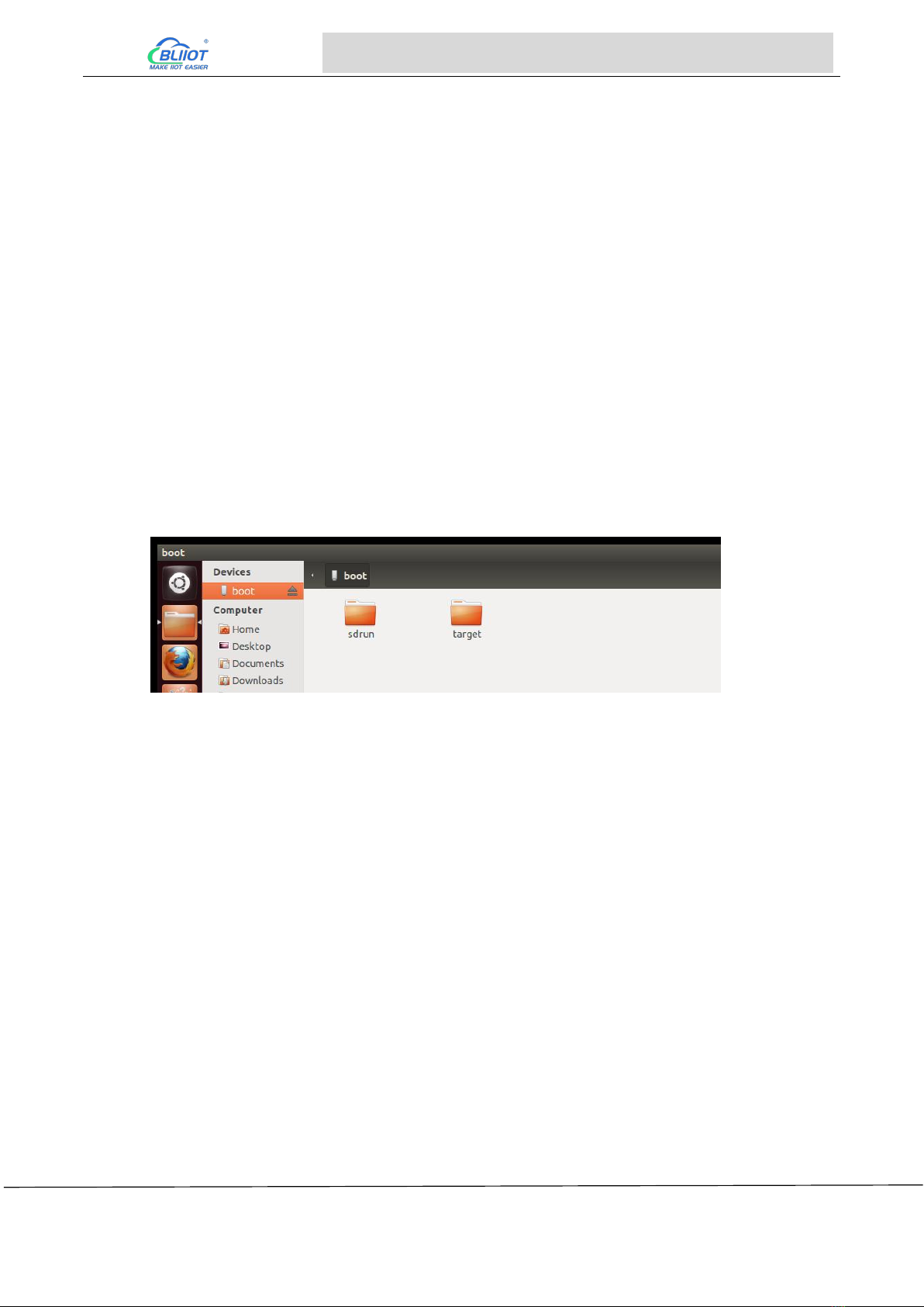
5) When the operation is complete, you will see that the boot partition contains two directories: sdrun
and target
The content of the sdrun folder is used to programming the system, it does not need to be modified;
The contents of the target directory will be written to the flash chip, if user has modified the mirror
image and needs to replace the mirror image file, just replace the corresponding file in the target
directory and keep the same name, then re-program the system.
The following is an introduction to the files in the target of the NAND SD programming:
u-boot-imx6ull14x14evk_nand.imx
BootLoader mirror image
zImage
kernel mirror image
okmx6ull-s-emmc.dtb
device Tree Mirroring
logo.bmp
Boot logo image
Users only need to make a bmp format
picture to replace the boot logo image (reference
method: User Profile\Application Notes), replace
the file with the name logo.bmp.
rootfs-console.tar.bz2
File system, no QT interface and QT library.
After the user creates a new file system,
name it as
Page 14 of 45 Pages Shenzhen Beilai Technology Co., Ltd.
V1.1
https://www.bliiot.com
Embedded ARM Computer BL301 BL302
rootfs_nogpu.tar.bz2 and replace this file,
you can program file system of your own.
modules.tar.bz2
Module file (unzip to the file system when
programming)
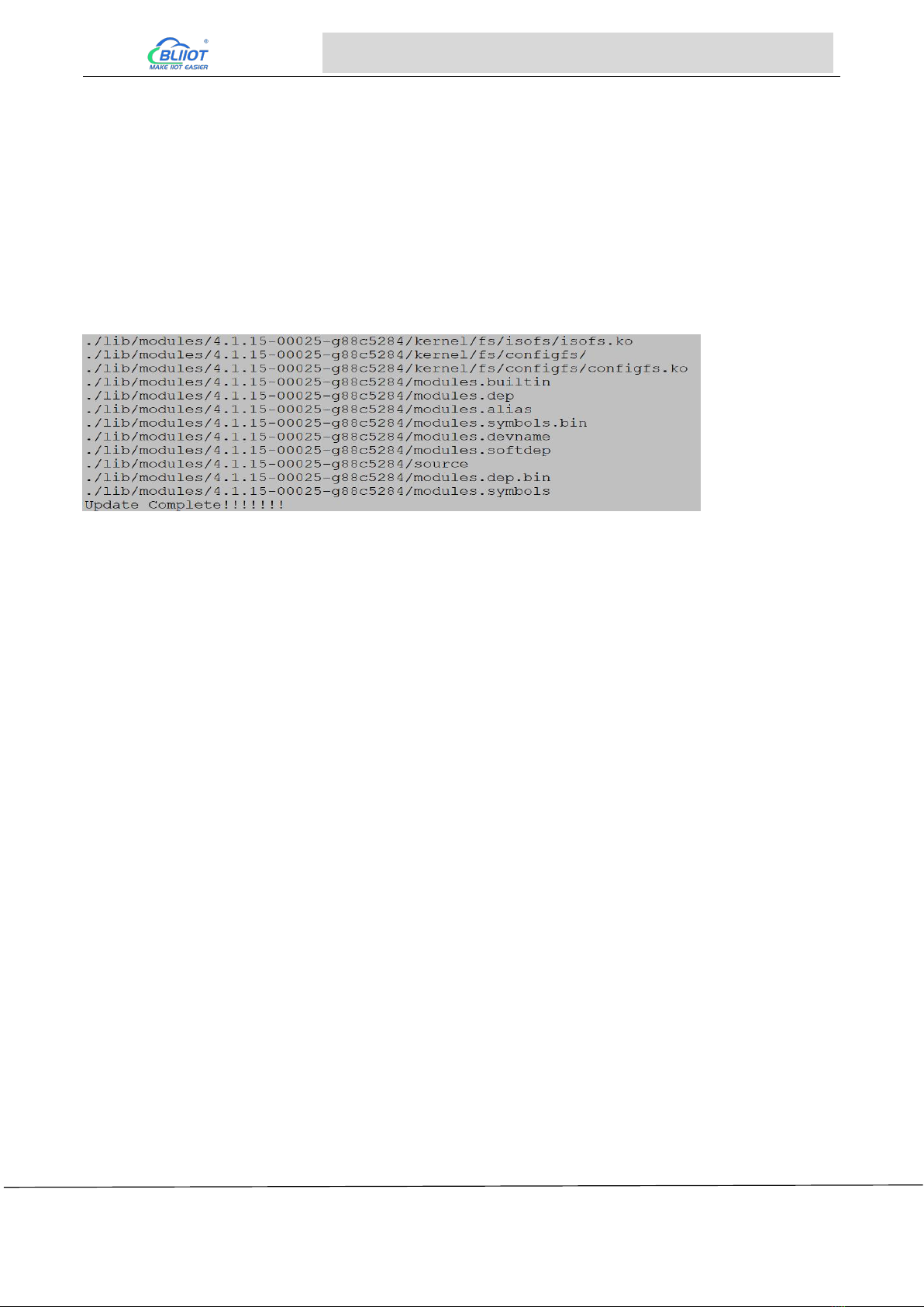
6) Insert the finished SD card in the previous section, and set the DIP switch as shown in the figure
below. 3, 5, 8 are ON, 1, 2, 4, 6, 7 are OFF, at this time, the content of the target in the SD card will be
programmed into eMMC. It takes a long time to programming. After the system programmed, the
serial port prints data:
7) At the same time LED1 on the backplane flashes.
8) When programming completed, turn off the power, turn the DIP switch to 3, 7 (ON), 1, 2, 4, 5, 6
and 8 (OFF), power on again, and NAND starts.
2.2.2 Programming via OTG
The eMMC core board defaults to the qt version of the file system. If you use the console version of
the file system, you can rename rootfs-console.tar.bz2 under the mfgtools\Profiles\Linux\OS
Firmware\files/linux path to rootfs -qt.tar.bz2
The OTG programming uses the board firmware programming tool mfgtools developed by NXP,
which can programming uboot, image, dtb, rootfs and other mirror images.
Following is a brief introduction to the files that users may use in the programming process.
The following paths start with: user profile\Linux\programming tools\OTG programming\mfgtools.
File name
Path
Description
mx6ull-4gemmc-
512mddr-qt5.6.vb
s
mfgtools
For programming eMMC core
board-related mirror images
mx6ull-256mnan
d-256mddr-cmd.v
bs
mfgtools
For programming 256M Nand
core board related mirror
images
ucl2.xml
Mfgtools\Profiles\Linux\OS
Firmware
Defines the specific operation
steps and operation content of

Page 15 of 45 Pages Shenzhen Beilai Technology Co., Ltd.
V1.1
https://www.bliiot.com
Embedded ARM Computer BL301 BL302
the programming process, users
can view this file for
instructions related to
single-step update
Boot the relevant
image
Mfgtools\Profiles\Linux\OS
Firmwarefirmware
The content of the folder is used
to guide the system to
programming, and generally
does not need to be modified
Mirror images
programming to
flash
Mfgtools\Profiles\Linux\OS
Firmware\files\linux
The content of the folder is used
to programming into the flash.
After the user modifies the
mirror image, rename it to the
same name and replace it,
which can be used to burn your
own mirror image
OTG programming method
Note: When using OTG programming, the SD card cannot be inserted.
User Profile\Linux\Tools\OTG\ mfgtools.rar is the path where the OTG programming tool is located
mx6ull-4gemmc-512mddr-qt5.6.vbs programming 4GeMMC+512MDDR system
1) Copy the programming tool Mfg tool to windows and decompress it. The path of the programming
tool is as follows: User Profile\Linux\Programming Tools\ mfgtools.zip
2) Turn the DIP switch to 1, 2 is ON, other states are arbitrary, try to be OFF
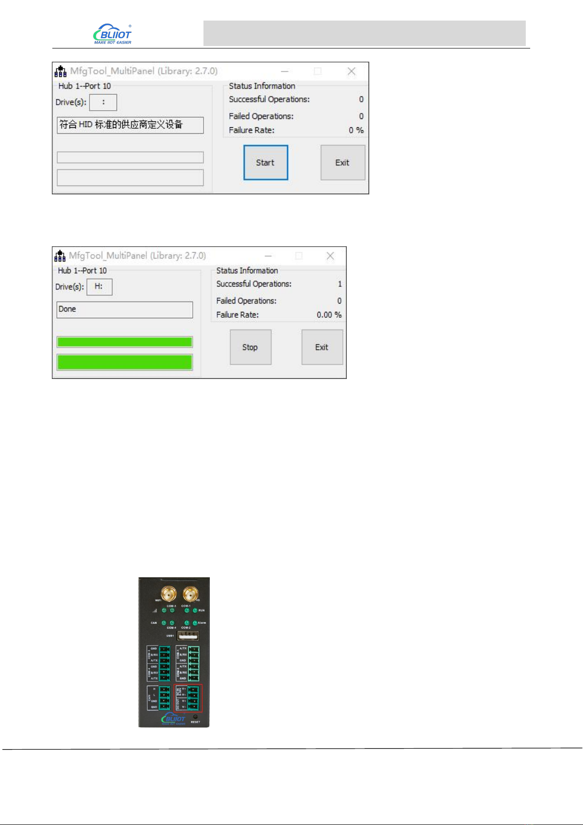
3) Double-click "mx6ull-256mnand-256mddr-cmd.vbs" (the script has been written and
programmed directly), as shown below:
Insert USB OTG, it will be automatically identified as HID, as shown in the figure:
Page 16 of 45 Pages Shenzhen Beilai Technology Co., Ltd.
V1.1
https://www.bliiot.com
Embedded ARM Computer BL301 BL302
Click start to start system programming, a formatting dialog box pops up, click the "Cancel" formatting
option, or leave it alone until the programming is complete. As shown in the picture:
After the system programming is completed, "Done" will appear, and then click "stop" to stop. Then
click "Exit" to close the programming tool. Power off, turn the DIP switch to 3, 7 are ON, 1, 2, 4, 5, 6, 8
are OFF, power on again, eMMC starts.
3 Hardware Specifications
3.1 Power Interface
BL302 comes with 1 power input and 1 power output. Support DC 9~36V input/output, anti-reverse
Page 17 of 45 Pages Shenzhen Beilai Technology Co., Ltd.
V1.1
https://www.bliiot.com
Embedded ARM Computer BL301 BL302
connection protection.
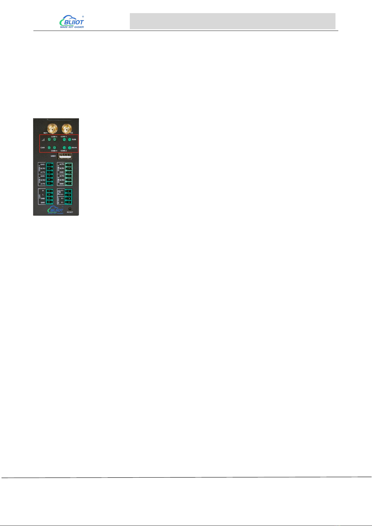
3.2 LED Indicators
The following figures shows the LED indicators, and the order from left to right and from top to bottom
is LED6, LED5, LED1, LED2, LED8, LED7, LED3, LED4, correspondence with the LEDs in the
/sys/class/leds directory.
View trigger conditions:
[none] means that the current trigger condition of led1 is none. Write the above string to trigger to
modify the trigger condition.
When the LED trigger condition is set to none, the user can control the LED light on and off through
commands.
Control LED1 on
root@fl-imx6ull:~# echo 1 > /sys/class/leds/led1/brightness
Control LED1 off
root@fl-imx6ull:~# echo 0 > /sys/class/leds/led1/brightness
The other 7 LED lights are similar, just change the /sys/class/leds to the LED light corresponding to
the corresponding ledx. Such as /sys/class/leds/led2/brightness
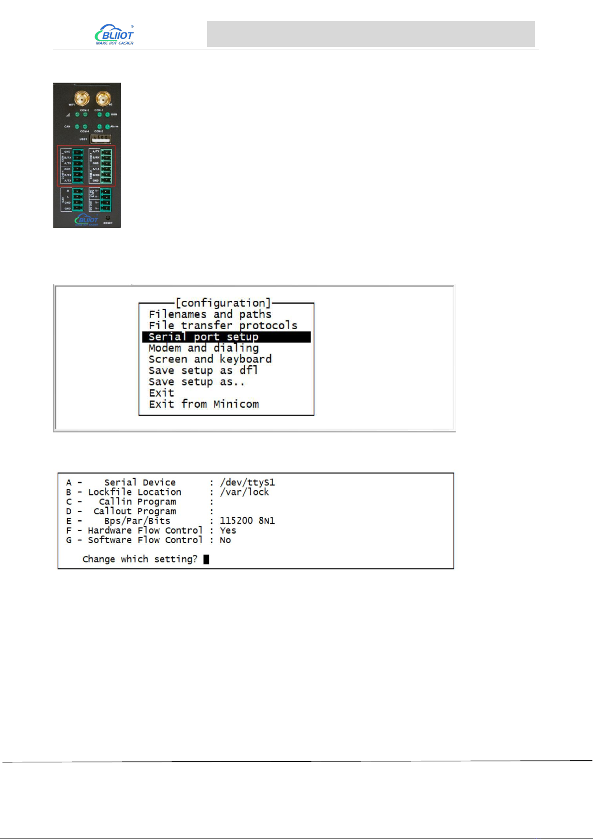
3.3 RS485&RS232 Serial Port
Depending on the chip on board, BL302 comes with RS485 or RS232. COM1, COM2, COM3 and
COM4 are corresponding to /dev/ttymxc1, /dev/ttymxc2, /dev/ttymxc5 and /dev/ttymxc4 respectively.
root@fl-imx6ull:~# cat /sys/class/leds/led1/trigger
[none] rc-feedback nand-disk mmc0 timer oneshot heartbeat backlight gpio
root@fl-imx6ull:~# echo none > /sys/class/leds/led1/trigger
Page 18 of 45 Pages Shenzhen Beilai Technology Co., Ltd.
V1.1
https://www.bliiot.com
Embedded ARM Computer BL301 BL302
The R485 serial port supports a maximum baud rate of 115200 with a cable length of 200 meters.
For debugging, enter "minicom -s" in the device, open the minicom configuration interface, and then
select "Serial port setup", as shown in the figure.
Select "Serial port setup" and press Enter to enter the setup menu, as shown in the figure.
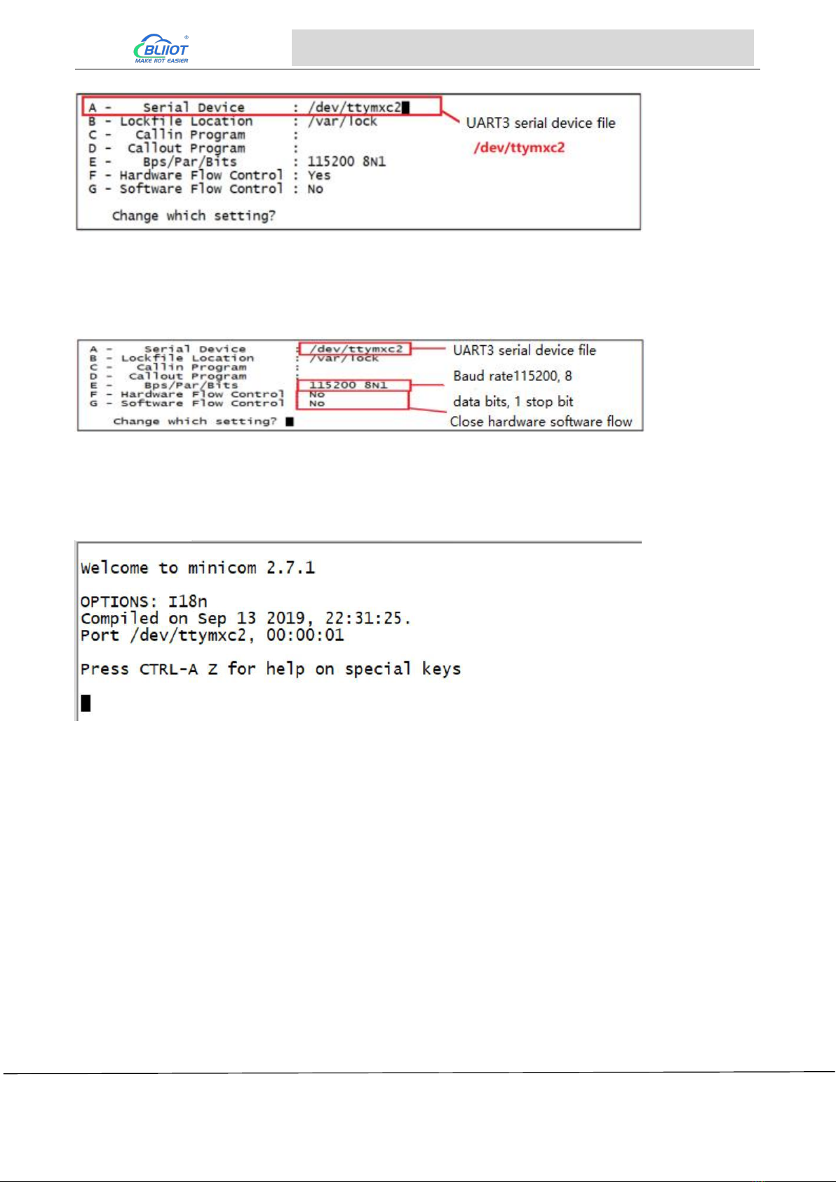
There are 7 setting items in the figure, corresponding to A, B...G, for example, the first one is to select
the serial port, which is /dev/ttymxc2, and the serial port file of UART3 is /dev/ttymxc2, so the serial
port setting should be set to /dev/ ttymxc2. . The setting method is to press 'A' on the keyboard, and
then enter "/dev/ttymxc2", as shown in the figure.
Page 19 of 45 Pages Shenzhen Beilai Technology Co., Ltd.
V1.1
https://www.bliiot.com
Embedded ARM Computer BL301 BL302
After setting, press the Enter key to confirm. After confirming, you can set other configuration items.
For example, E sets the baud rate, data bits and stop bits, and F sets the hardware flow control, the
setting methods are the same, as shown in the figure after setting.
After all settings are completed, press the Enter key to confirm and exit. At this time, it will return to
the interface of the setting menu. Press the ESC key to exit the interface of the setting menu. After
exiting, it will be as shown in the figure.
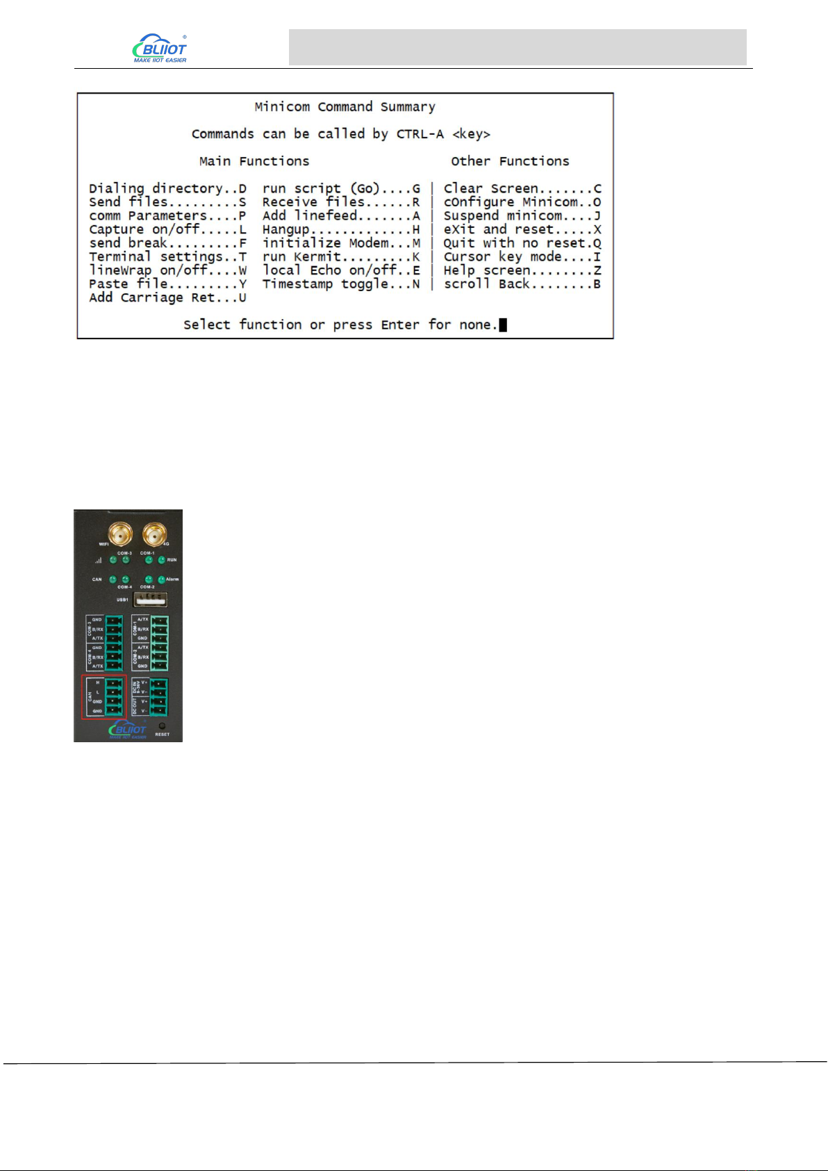
This is the serial port debugging interface. It can be seen that the current serial port file is
/dev/ttymxc2, press CTRL-A, and then press Z to open the minicom help information interface, as
shown in the figure.
Page 20 of 45 Pages Shenzhen Beilai Technology Co., Ltd.
V1.1
https://www.bliiot.com
Embedded ARM Computer BL301 BL302
The minicom has many shortcut keys. In this experiment, we enable the echo function of minicom.
The echo function configuration item is "local Echo on/off..E", press E to turn on/off the echo display
function.
3.4 CAN Interface
The CAN interface is as shown in the figure, enter the following command:
ifconfig -a //View all network cards
If the FlexCAN driver works well, you will see the network card interface corresponding to CAN, as
shown in the figure, there is a network card named "can0", which is the CAN network card
corresponding to the CAN1 interface on the BL302 board.
This manual suits for next models
3
Table of contents
Other BLIIoT Industrial PC manuals


