BLIIoT S275 User manual
Cellular IoT M2M RTU
S275
User Manual
Version: V1.1
Date: 2022-10-21
Shenzhen Beilai Technology Co., Ltd
Website: https://www.bliiot.com

Page 2 of 74 Shezhen Beilai Technology Co., Ltd V1.1
Cellular IoT M2M RTU --- S272/S274/S275
Preface
Thanks for choosing BLIIoT Cellular IoT M2M RTU. These operating instructions contain all the
information you need for operation of a device in the RTU S27 family.
Copyright
This user manual is owned by Shenzhen Beilai Technology Co., Ltd. No one is authorized to copy,
distribute or forward any part of this document without written approval of Shenzhen Beilai
Technology. Any violation will be subject to legal liability.
Disclaimer
This document is designed for assisting user to better understand the device. As the described
device is under continuous improvement, this manual may be updated or revised from time to time
without prior notice. Please follow the instructions in the manual. Any damages caused by wrong
operation will be beyond warranty.
Revision History
Revision Date
Version
Description
Owner
November 30th, 2021
V1.0
Initial Release
XJH
October 21st, 2022
V1.1
LKY

Page 3 of 74 Shezhen Beilai Technology Co., Ltd V1.1
Cellular IoT M2M RTU --- S272/S274/S275
Content
1 Introduction ................................................................................................................................................ 6
1.1 Overview .............................................................................................................................................6
1.2 Typically Applications ........................................................................................................................6
1.3 Safety Directions ............................................................................................................................... 7
1.4 Packing List ........................................................................................................................................ 8
1.5 Features ..............................................................................................................................................8
1.6 Technical Specifications................................................................................................................. 10
1.7 Model Selection ............................................................................................................................... 12
2 Hardware Specifications ........................................................................................................................13
2.1 Size ....................................................................................................................................................13
2.2 Interface ............................................................................................................................................ 14
2.2.1 Digital Input ............................................................................................................................... 14
2.2.2 LED Indicators .......................................................................................................................... 15
2.2.3 Digital Output ............................................................................................................................16
2.2.4 Analog Input .............................................................................................................................. 16
2.2.5 RS485 and Temperature&Humidity...................................................................................... 17
2.2.6 Power&Switch&Mode Settings.............................................................................................. 17
2.2.7 SIM Card Slot........................................................................................................................... 18
3 Installation ................................................................................................................................................18
3.1 Wall mounted ................................................................................................................................... 18
3.2 DIN Rail mounting ........................................................................................................................... 19
4 Configuration ........................................................................................................................................... 19
4.1 Preparation before configuration .................................................................................................. 19
4.1.1 Install USB Driver .....................................................................................................................20
4.1.2 Check COM Port ...................................................................................................................... 21
4.1.3 Login Configuration Software .................................................................................................21
4.2 Basic Settings .................................................................................................................................. 22
4.3 Alarm Numbers Settings................................................................................................................ 24
4.4 Digital Output Settings ....................................................................................................................25
4.5 Access Control Settings ................................................................................................................. 26

Page 4 of 74 Shezhen Beilai Technology Co., Ltd V1.1
Cellular IoT M2M RTU --- S272/S274/S275
4.6 Input Settings ................................................................................................................................... 27
4.6.1 DI Setting ...................................................................................................................................27
4.6.2 DI Alarm Settings..................................................................................................................... 30
4.6.3 AI Setting ................................................................................................................................... 30
4.6.4 AI Alarm Settings ......................................................................................................................32
4.7 Timer Setting .................................................................................................................................... 33
4.8 Logic Trigger Setting .......................................................................................................................34
4.9 Serial Port Settings ......................................................................................................................... 35
4.10 Modbus RTU Slave Settings ....................................................................................................... 37
4.10.1 Slave Mapping List ................................................................................................................ 37
4.10.2 Mapping Register ...................................................................................................................40
4.11 Network Settings ........................................................................................................................... 41
4.12 Historical Record...........................................................................................................................43
4.13 System............................................................................................................................................ 44
4.13.1 Export Configuration File ......................................................................................................44
4.13.2 Import Configuration File ...................................................................................................... 45
4.14.3 Factory Reset ......................................................................................................................... 45
5 SMS Functions ........................................................................................................................................45
5.1 SMS Command List ........................................................................................................................ 45
6 Communication Protocols ..................................................................................................................... 49
6.1 Modbus RTU Slave Application .................................................................................................... 51
6.1.1 Read DO State......................................................................................................................... 51
6.1.2 Control DO ................................................................................................................................ 52
6.1.3 Read DI State........................................................................................................................... 54
6.1.4 Read AI, Tem&Hum, DI0, Power value ................................................................................ 55
6.2 Modbus RTU Master Application .................................................................................................. 57
6.2.1 Read Bool Mapping Address Data........................................................................................ 58
6.2.2 Revise Bool Mapping Address Data..................................................................................... 59
6.2.3 Read Data Type Mapping Address....................................................................................... 60
6.2.4 Revise Data Type Mapping Address .....................................................................................61
7 Connect to Cloud Platform.................................................................................................................... 62
7.1 BLIIoT Modbus Cloud .....................................................................................................................62

Page 5 of 74 Shezhen Beilai Technology Co., Ltd V1.1
Cellular IoT M2M RTU --- S272/S274/S275
7.2 BLIIoT MQTT Cloud ........................................................................................................................65
7.3 Other IoT Server ..............................................................................................................................69
8 Register .................................................................................................................................................... 70
8.1 Device Register Address................................................................................................................70
8.2 Mapping Register............................................................................................................................ 72
9 Upgrade ....................................................................................................................................................74
10 Warranty Term...................................................................................................................................... 74
11 Technical Support ................................................................................................................................ 74

Page 6 of 74 Shezhen Beilai Technology Co., Ltd V1.1
Cellular IoT M2M RTU --- S272/S274/S275
1 Introduction
1.1 Overview
The Cellular IoT M2M RTU is an industrial class, high reliability, high stability, and programmable
Remote Terminal Unit (RTU). It embedded 32-Bit High Performance Microprocessor MCU, inbuilt
industrial Cellular module. The RTU features 8 digital inputs, 6 analog inputs, 4 relay outputs, 1
ambient sensor input for monitoring onsite temperature and humidity, and 1 RS485 serial port. And as
Modbus master, the RTU can connect to expansion I/O module or read data from instruments, PLC
and other devices.
Users can set high and low limit according to different application scenarios, when alarm occurs, the
RTU will notify users by SMS, dialing, and also uploading data to cloud platform, monitoring center.
The RTU also can be used as a remote switch, remote I/O, remote smart PLC, timer switches, which
is able to open the gate or turn on the machine with a free charge call at specified time to save time
for daily maintenance.
The RTU supports BLIIoT IoT RTU protocol, Modbus RTU over TCP protocol, Modbus TCP protocol,
MQTT protocol, which can communicate directly with the server, cloud platform or SCADA. It is a cost
effective IoT solution for industrial automation, security monitoring system, automatically
measurement and control system, BTS monitoring, remote data acquisition, telemetry systems,
automatically control system.
1.2 Typically Applications
BTS Monitoring, Security Alarm System applications, Supervision and monitoring alarm systems,
Automatic monitoring system, Vending Machines security protection, Pumping Stations, Tanks, Oil or
Water levels, Buildings and Real Estate, Weather Stations, River Monitoring and Flood Control, Oil
and gas pipelines, Corrosion protection, Temperatures, Water leakage applications, Wellheads, boat,
vehicle, Energy saving, street lights control system, Valve controls, Transformer stations, Unmanned
machine rooms, Control room application, Automation System, M2M, Access Control System, etc.

Page 7 of 74 Shezhen Beilai Technology Co., Ltd V1.1
Cellular IoT M2M RTU --- S272/S274/S275
1.3 Safety Directions
Safe Startup
Do not use the unit when using GSM/3G/4G equipment is prohibited or might bring
disturbance or danger.
Interference
All wireless equipment might interfere network signals of the unit and influence its
performance.

Page 8 of 74 Shezhen Beilai Technology Co., Ltd V1.1
Cellular IoT M2M RTU --- S272/S274/S275
1.4 Packing List
Please make sure below items are included in the package:
(Pictures are for reference only)
1xRTU, Wiring terminal, 1xMini USB, 1xSMA cellular antenna, 1xPower adaptor, Wall-mounting
clip kit, DIN-Rail mounting clip kit, Product qualification certificate, Warranty card
1.5 Features
GSM/GPRS/3G/4G network communication, can be operated from anywhere, no distance
limitation;
Wide range power supply 9~36VDC with over voltage and phase-reversal protection;
Embedded ARM Cortex-M4 32 Bit RISC Core, 168 MHz inside, RTOS system, reliable
performance with in-built watchdog;
8 digital inputs, supports both dry contact and wet contact. Logic level: 10~30V or short circuit

Page 9 of 74 Shezhen Beilai Technology Co., Ltd V1.1
Cellular IoT M2M RTU --- S272/S274/S275
treated as close, 0~3V or open circuits treated as open. DIN0 as a high-speed pulse counter,
sampling frequency: 1MHz; DIN1~3 as low-speed pulse counter, anti-shake time can be set
1~2000ms, default 1ms; DIN1 with arm and disarm function;
4 relay output (5A@30VDC, 5A@250VAC), can auto control by timer, alarm-link and remote
control by SMS, cloud. The first DO can set time to control by authorize number;
1 temperature & humidity sensor input for monitoring onsite environment, the sensor model is
AM2301, temperatures range from -40°C to 80°C, with a 0.5°C accuracy, humidity range from 0
to 100RH%, with a 3% accuracy;
6 analog inputs, 12bits resolution, supports 0-5V, 0-20mA, 4-20mA output transducers;
Inbuilt 32G SD card to save up to tens of thousands historical data and events;
1 RS485 port, support Modbus slave protocol, can link up to SCADA, HMI, DSC, PLC. Support
Modbus Master protocol, can connect to 16 Modbus Salve, e.g.: Data Acquisition Module,
meters, generator, PLC, VFD, etc., and 320 tags can set alarm value and content, also support
data transparent transmission;
Powerful SMS function: Threshold high SMS alert, SMS set, SMS inquiry, SMS command for
Modbus PLC, and SMS monitoring communication with Slaves;
Inbuilt 2 DC output for external transducers to save wiring cost;
Automatically resend the data while communication interrupt or failure, and failure will alert by
SMS;
Supports remotely restart. configure and operate by SMS commands;
10 SMS Alert and auto dial numbers for receiving alarm message, can program to receive
specified alarm message. The authorized numbers also can dial to open the door or turn on/off
machine with a free charge call at the specified time;
Inbuilt inter-lock logic programmer and powerful timer program function;
Modular structure, replace a module to upgrade the network from 2G to 3G/4G or 3G to 4G;
Support SMS, dial, GPRS, 3G , 4G network for alert, USB port for configuration and upgrade
firmware;
Inbuilt large capacity rechargeable backup battery, which is able to alert when external power
failure;
Support TCP/UDP, MQTT, Modbus TCP, Modbus RTU over TCP, BLIIoT IoT RTU protocol and
data transparent transmission;
Page 10 of 74 Shezhen Beilai Technology Co., Ltd V1.1
Cellular IoT M2M RTU --- S272/S274/S275
Metal case with IP30 protection grade, safely isolated from inner system, especially suitable for
industrial control application.
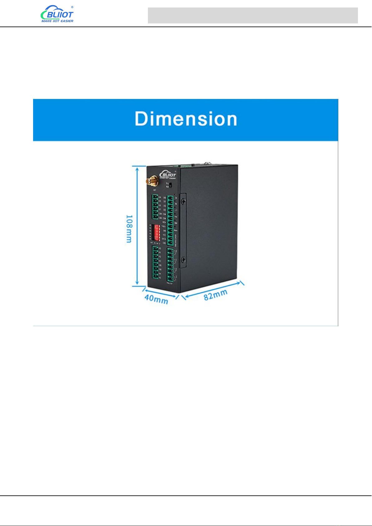
Small size: 108mmx82mmx40mm, support wall-mounting and DIN Rail mounting.
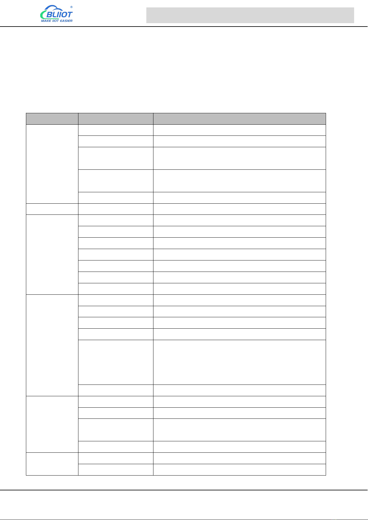
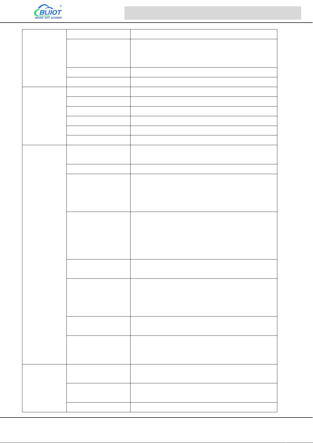
1.6 Technical Specifications
Category
Parameter
Description
Power
Input Voltage
DC 9~36V
Power Consumption
Normal: 50mA@12V, Max: 150mA@12V
Output
2 Channel; Voltage: 9~36V DC; Current:
1500mA@12V(Max)
Protection
Reverse wiring prevention;
ESD Air: 15KV; Surge: 4KV
Backup Battery
3.7V/900mA
USB
USB
1xMini USB
Serial Port
QTY
1xRS485
Baud Rate
1200bps-115200bps
Data Bit
8
Parity Bit
None, Even, Odd
Stop Bit
1, 2
Protocol
Modbus RTU(slave), Modbus RTU(master)
Protection
ESD Contact: 8KV; Surge: 4KV(8/20us)
Digital Input
QTY
8 Channel
Type
Support both Wet contact and Dry contact
Dry Contact
Close: Short circuit; Open: Open circuits
Wet Contact
Close: 10~30V; Open: 0~3V
Others
DIN0 as a high-speed pulse counter, sampling
frequency: 1MHz; DIN1~3 as low-speed pulse counter,
anti-shake time can be set 1~2000ms, default 1ms;
DIN1 with arm and disarm function;
Protection
2KVrms
Digital Output
QTY
4 Channel
Type
Relay output (5A@30VDC, 5A@250VAC)
Others
The first DO can set time to control by authorize
number; Custom setting close and open times
Protection
2KVrms
Analog Input
QTY
6 Channel
Type
Differential input, 4-20mA/0-20mA/0-5V
Page 11 of 74 Shezhen Beilai Technology Co., Ltd V1.1
Cellular IoT M2M RTU --- S272/S274/S275
Resolution
12Bit
Accuracy
±0.1% FSR @ 25°C
±0.3% FSR @ -10 and 60°C
±0.5% FSR @ -40 and 75°C
Sampling Rate
200ms
Input Impedance
>1M ohms
Temperature&
Humidity
(AM2301)
Resolution
16bit(0.1%RH, 0.1°C)
Sampling Rate
200ms
Temperature Range
-40 to +80°C
Accuracy
0.5°C
Humidity Range
0 to 99RH%
Accuracy
3%RH
4G
SIM
Drawer type, Support 1.8V/3V SIM/UIM card, Built-in
15KV ESD protection
SIM Slot
1
L-E Version
GSM/EDGE:900,1800MHz
WCDMA:B1,B5,B8
FDD-LTE:B1,B3,B5,B7,B8,B20
TDD-LTE:B38,B40,B41
L-CE Version
GSM/EDGE:900,1800MHz
WCDMA:B1,B8
TD-SCDMA:B34,B39
FDD-LTE:B1,B3,B8
TDD-LTE:B38,B39,B40,B41
L-A Version
WCDMA:B2,B4,B5
FDD-LTE:B2,B4,B12
L-AU Version
GSM/EDGE:850,900,1800MHz
WCDMA:B1,B2,B5,B8
FDD-LTE:B1,B3,B4,B5,B7,B8,B28
TDD-LTE:B40
L-AF Version
WCDMA:B2,B4,B5
FDD-LTE:B2,B4,B5,B12,B13,B14,B66,B71
CAT-1 Version
GSM:900,1800
FDD-LTE:B1,B3,B5,B8
TDD-LTE:B34,B38,B39,B40,B41
Software
Internet Protocol
IPV4, TCP/UDP, Modbus RTU, Modbus TCP, MQTT,
BLIIoT IoT RTU
Indicator
4G signal, running, arming and disarming, 485
transmit-receive
Configuration
PC software configuration, support WIN XP, WIN 7,

Page 12 of 74 Shezhen Beilai Technology Co., Ltd V1.1
Cellular IoT M2M RTU --- S272/S274/S275
WIN 8 and WIN 10
Slave Connection
16 devices, Max 320 I/O data points(Bool, 16bit, 32bit,
64bit)
Transparent
Transmission
Support
SMS Command
Support
Login Package
Support custom login package
Heartbeat Package
Support custom heartbeat package
Storage
Built in 32G SD card, capable of storing up to 100,000
historical records
Safety
MTBF
≥100,000 hours
EMC
EN 55022: 2006/A1: 2007 (CE &RE) Class B
IEC 61000-4-2 (ESD) Level 4
IEC 61000-4-3 (RS) Level 4
IEC 61000-4-4 (EFT) Level 4
IEC 61000-4-5 (Surge)Level 3
IEC 61000-4-6 (CS)Level 4
IEC 61000-4-8 (M/S) Level 4
Others
CE, FCC, RoHS
Environment
Working
-45~85°C, 5~95% RH
Storage
-45~105°C, 5~95% RH
Others
Shell
Metal
Size
108x82x40mm
Protection
IP30
Installation
Wall-mounting or DIN Rail mounting.
1.7 Model Selection
Model
DI
AI
DO
Tem&
Hum
Storage
USB
RS485
I/O data points
bool
16Bit
32Bit
64Bit
S270
2
2
2
1
2M
1
x
x
x
x
x
S271
4
4
4
1
2M
1
x
x
x
x
x
S272
8
6
4
1
32G
1
1
64
64
x
x
S274
4
x
4
1
32G
1
1
64
128
64
64
S275
8
6
4
1
32G
1
1
64
128
64
64
Page 13 of 74 Shezhen Beilai Technology Co., Ltd V1.1
Cellular IoT M2M RTU --- S272/S274/S275
2 Hardware Specifications
2.1 Size

Page 14 of 74 Shezhen Beilai Technology Co., Ltd V1.1
Cellular IoT M2M RTU --- S272/S274/S275
2.2 Interface
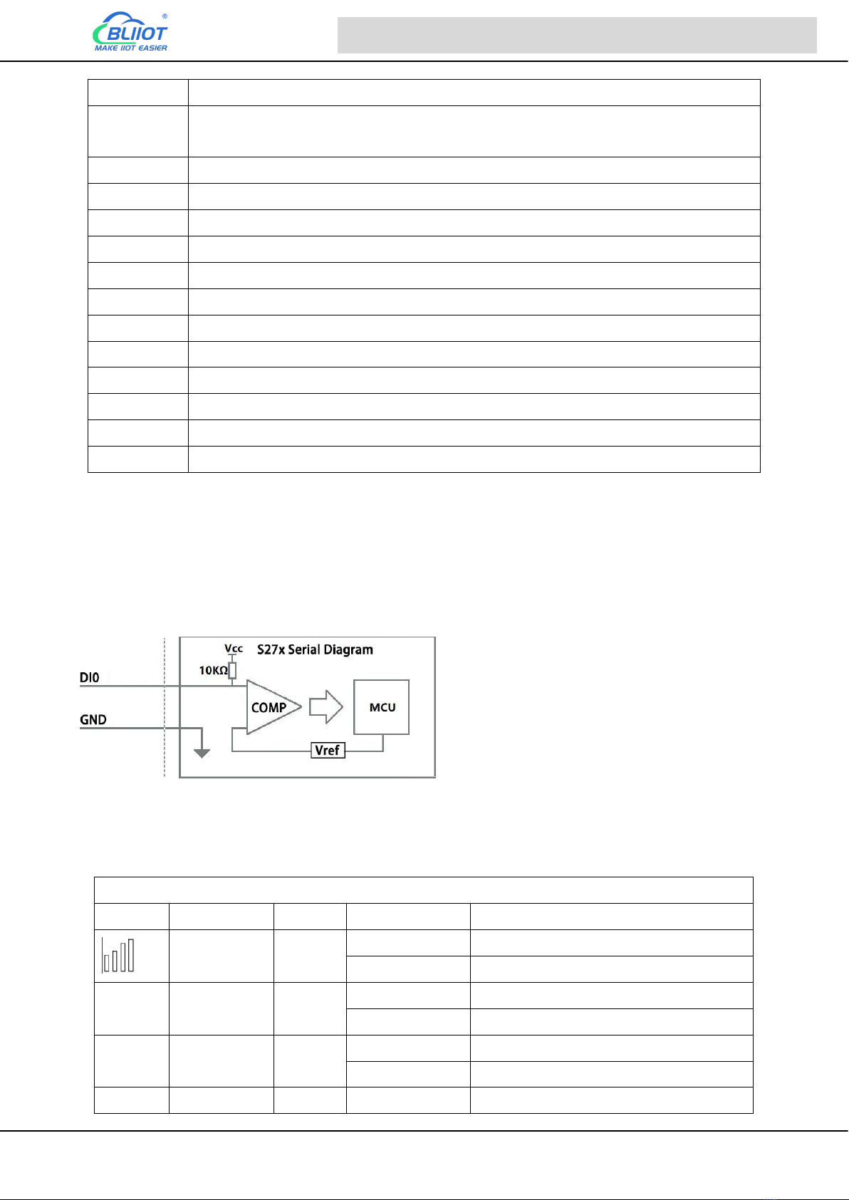
2.2.1 Digital Input
Digital Input
Function
Description
DI0
First channel of Digital input, support high speed pulse counting, sampling
Page 15 of 74 Shezhen Beilai Technology Co., Ltd V1.1
Cellular IoT M2M RTU --- S272/S274/S275
frequency: 1MHz
DI1
Second channel of Digital input, support low speed pulse counting, support used
as arming and disarming input
DI2
Third channel of Digital input, support low speed pulse counting
DI3
Fourth channel of Digital input, support low speed pulse counting
COM
Common grounding
COM
Common grounding
DI4
Fifth channel of Digital input
DI5
Sixth channel of Digital input
DI6
Seventh channel of Digital input
DI7
Eighth channel of Digital input
COM
Common grounding
COM
Common grounding
Dry
DI switch to Dry contact
Wet
DI switch to Wet contact
Note: DIN0 as a high-speed pulse counter, sampling frequency: 1MHz; DIN1~3 as low-speed pulse
counter, anti-shake time can be set 1~2000ms, default 1ms;
When using the counter function, please swtich the DIP switch on device to Wet.
Diagram of DI internal interface:
2.2.2 LED Indicators
LED Indicators
Symbol
Name
Color
State
Description
4G signal
RED
Always ON
Normal
OFF
4G module abnormal
Alarm
Alarm
RED
Always ON
Triggered alarm
OFF
No alarm
Run
Run
RED
Flickering
System is running
OFF
System stop running
Arm
Arm
RED
Always ON
Armed

Page 16 of 74 Shezhen Beilai Technology Co., Ltd V1.1
Cellular IoT M2M RTU --- S272/S274/S275
OFF
Disarmed
TX
Transmit via
serial port
RED
Flickering
Data communication via RS485 serial
port
OFF
No data
RX
Receive via
serial port
RED
Flickering
Data communication via RS485 serial
port
OFF
No data
2.2.3 Digital Output
Digital Output
Functions
Description
DO0+
First channel of Digital output
DO0-
First channel of Digital output
DO1+
Second channel of Digital output
DO1-
Second channel of Digital output
DO2+
Third channel of Digital output
DO2-
Third channel of Digital output
DO3+
Fourth channel of Digital output
DO3-
Fourth channel of Digital output
Diagram of DO internal interface:
2.2.4 Analog Input
Mode selection(DIP Switch)
Functions
Description
V
Switch to "V" indicate that the analog input type is "0-5V"
mA
Switch to "mA" indicate that the analog input type is "0-20mA" or "4-20mA"
A0-A5
Corresponding to the analog input of each channel

Page 17 of 74 Shezhen Beilai Technology Co., Ltd V1.1
Cellular IoT M2M RTU --- S272/S274/S275
Note: According to the output type of the transmitter(mA or V), switch the DIP switch of the
corresponding channel to the corresponding position on the device.
Analog Input
Functions
Description
AI0
First channel of Analog input positive interface
AI1
Second channel of Analog input positive interface
AI2
Third channel of Analog input positive interface
AI3
Fourth channel of Analog input positive interface
GND
Common grounding
GND
Common grounding
AI4
Fifth channel of Analog input positive interface
AI5
Sixth channel of Analog input positive interface
Diagram of AI internal interface:
2.2.5 RS485 and Temperature&Humidity
RS485 and Temperature&Humidity
Functions
Description
485+
RS485 A +
485-
RS485 B -
GND
485 Grounding
VCC
Power supply interface of Tem &Hum sensor(AM230x/AM240x)
DATA
Data interface of Tem &Hum sensor(AM230x/AM240x)
GND
Grounding of Tem &Hum sensor(AM230x/AM240x)
2.2.6 Power&Switch&Mode Settings
Power&Switch&Mode Settings
Page 18 of 74 Shezhen Beilai Technology Co., Ltd V1.1
Cellular IoT M2M RTU --- S272/S274/S275
Functions
Description
VIN+
9-36V Power input positive
VIN-
9-36V Power input negative
VOUT+
9-36V Output positive
VOUT-
9-36V Output negative
OFF
Device shutdown
ON
Device startup
SET
Switch to SET to enter configuration mode when configuring
RUN
When configuring is complete, switch to RUN to enter the running
mode.
USB
Used to connect configuration software, set parameters, and
upgrade
2.2.7 SIM Card Slot
When inserting/removing the SIM card, please turn off the device.
Note: Please place the device flat when inserting/removing the SIM card.
3 Installation
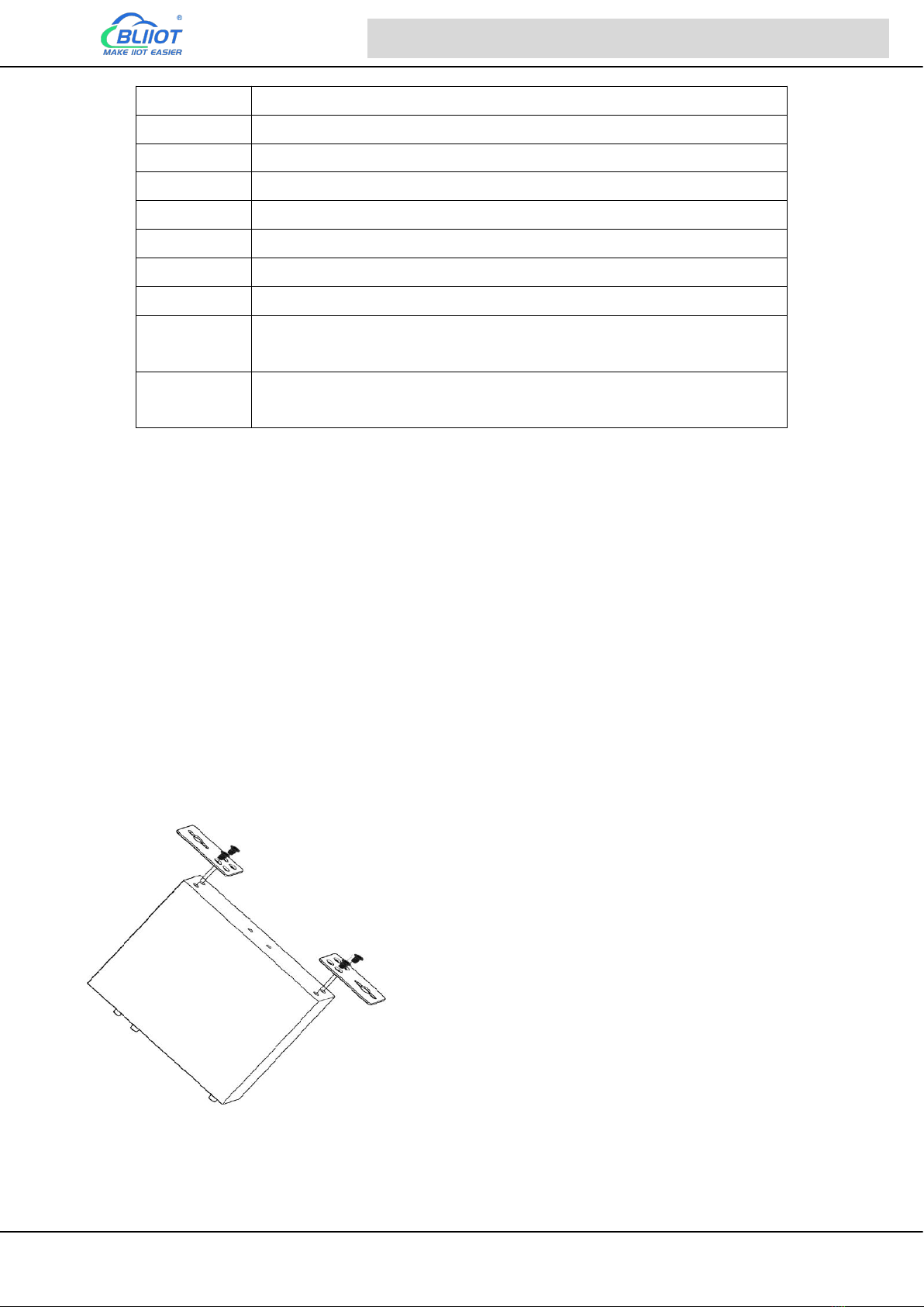
3.1 Wall mounted

Page 19 of 74 Shezhen Beilai Technology Co., Ltd V1.1
Cellular IoT M2M RTU --- S272/S274/S275
3.2 DIN Rail mounting
4 Configuration
4.1 Preparation before configuration
Please follow the steps
1) Insert the SIM Card;
2) The device must be configured in [SET] mode, switch to [SET] before configuration;
3) Connect the device to an external power and power on, switch the power switch to ON.
Please switch to SET mode first, then power on the device.

Page 20 of 74 Shezhen Beilai Technology Co., Ltd V1.1
Cellular IoT M2M RTU --- S272/S274/S275
4) Connect the RTU to PC by USB cable, and install the USB Driver to the computer;
5) Open configuration software, choose the correct COM port and fill in the password(Default:
1234), select Normal SIM card mode to enter configuration software;
6) Open parameter setting page---->Click "Read" button to get device current value--->After
modifying or setting the parameters---->Click the "Save" button to saving parameters in device;
7) If you need to program bulks of RTU with similar parameters, you can [Export Configuration File],
and then [Import Configuration File] to the next device to complete the settings quickly;
8) Power off the device when configuration is complete, switch the power switch to OFF;
9) Switch to [RUN] mode after power off the device;
10) Reboot the device, then the device will enter into normal running mode.
Notice:
1, The device must be configured in [SET] mode, switch to [SET] before power ON the device;
2, Click the "Save" button to saving parameters in device;
3, When configuration is complete, power OFF the device, then switch to [RUN] mode;
4.1.1 Install USB Driver
Install the USB Driver to the computer firstly. When successful, it can be found out at the device
manager of the XP or Windows 7 or Win8/Win10. Also, the driver for different OS can be downloaded
from Silicon Laboratories, Inc. http://www.silabs.com , the model is CP210x.
This manual suits for next models
2
Table of contents
Other BLIIoT Industrial PC manuals


Popular Industrial PC manuals by other brands


GIGAIPC
GIGAIPC QBiX-Pro Series quick start guide

Advantech
Advantech IPPC-9151 Series Mounting installation guide

IEI Technology
IEI Technology PXE-12S Quick installation guide

NemaVision-iPC
NemaVision-iPC NV-HMI-717P user manual

Lenovo
Lenovo ThinkCentre M70c Hardware Maintenance Manual

adstec
adstec IRF3000 Series quick start guide