BLIP BLN2i-WF User manual

08-01-2017
Installation manual
BlipTrack BNL2i-WF v1.1
BLIP Systems A/S · support@blipsystems.com · +45 98847202 · www.blipsystems.com
ENGLISH - INDOOR SENSOR
INSTALLATION MANUAL – BLN2i-WF

Page 2 of 11
08-01-2017
Installation manual
BlipTrack BNL2i-WF v1.1
INSTALLATION MANUAL – BNL2i-WF
- TABLE OF CONTENTS
Storage of BlipTrack BNL2iWF:
There are no special storage concerns to be observed for this unit
This and other handling manuals (preparation, installation, troubleshooting, storage,
maintenance and other general information) can be found on BLIP Systems web-page:
http://www.blipsystems.com/download/
Contents
Step 1 - Preparations 3
Step 2 - Remove side panels and top lid for mounting access 4
Step 3 - Create cable access 5
Step 4 - Mount the unit safely at the measuring point 6
Step 5 - Connect the unit to the PoE LAN network 7
Step 6 - Check the power-on sequence 8
Step 7 - Fasten the lid and side panels of the unit 9
Step 8 - Await unit conguration 10
Step 9 - Complete the installation 11
Page 3 of 11
08-01-2017
Installation manual
BlipTrack BNL2i-WF v1.1
INSTALLATION MANUAL – BNL2i-WF
STEP 1 - PREPARATIONS
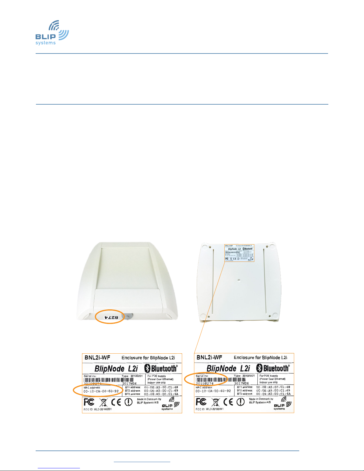
1. Check by visual inspection that the unit is undamaged.
2. The serial number and the MAC address are found from the label on the back of the
unit.
3. Check the unit has the correct serial number as agreed with BLIP Systems.
4. Record the MAC address of the unit for the conguration stage.
5. The unit has been fully tested at BLIP Systems prior to shipment so the unit can
be installed “out-of-the-box” at the measurement point without any further
preparations.
6. A LAN cable with PoE (Power over Ethernet) shall be available at the measurement
point.
Back
MAC Address Serial number
Page 4 of 11
08-01-2017
Installation manual
BlipTrack BNL2i-WF v1.1
INSTALLATION MANUAL – BNL2i-WF
STEP 2
- REMOVE SIDE PANELS AND TOP LID FOR MOUNTING ACCESS
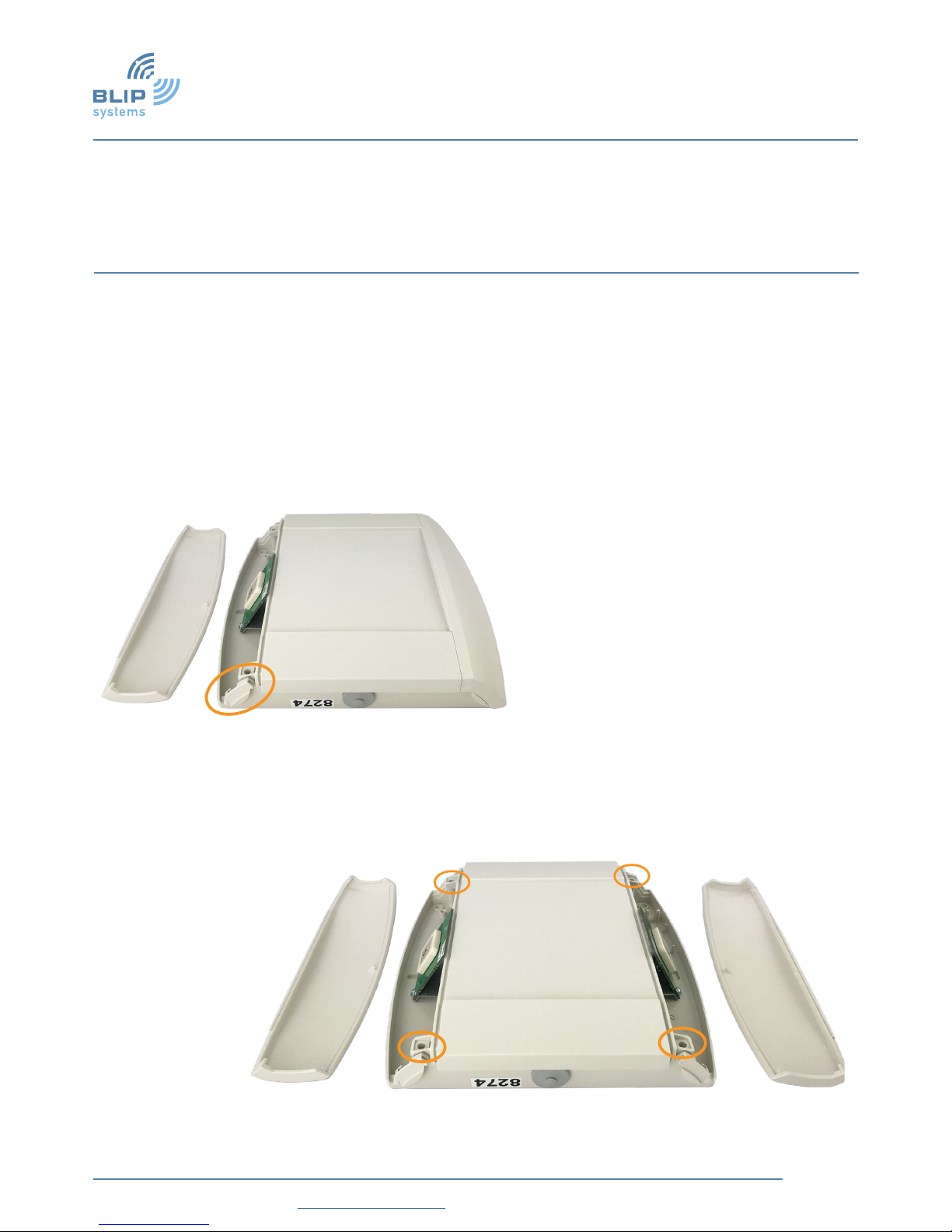
• The two side panels are released by pressing the small wings and lifting the
side panels upwards.
• Remove the lid by unscrewing the four screws. (Lift the lid carefully to avoid
damaging the green antennas)
Small wing
Four screws

Page 5 of 11
08-01-2017
Installation manual
BlipTrack BNL2i-WF v1.1
INSTALLATION MANUAL – BNL2i-WF
STEP 3 - CREATE CABLE ACCESS
To ease creating the cable access the L2i module may be removed.
1. Remove the USB cable from the L2i-module.
2. Remove the L2i module from the unit by lifting it upwards.
3. Cut the rubber cable entry open for normal LAN cable access/Or drill a hole in
the cabinet if the LAN cable shall enter the unit through the back pane.
4. Mount the L2i module again by pressing it rmly onto the four taps.
5. Reattach the USB cable.
USB Cable
Tabs for the L2i module
Entry for LAN Cable
Page 6 of 11
08-01-2017
Installation manual
BlipTrack BNL2i-WF v1.1
INSTALLATION MANUAL – BNL2i-WF
STEP 4 - MOUNT THE UNIT SAFELY AT THE MEASURING POINT
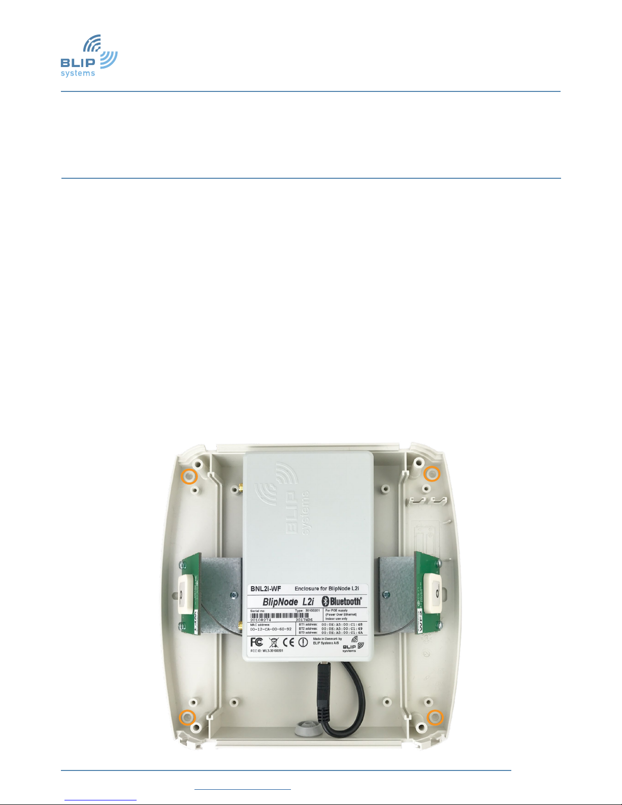
• It is recommended to use the prepared mounting locations within the
cabinet when mounting the unit.
• If the PoE LAN cable shall enter the unit through the cabinet then feed the
cable through before mounting the unit.
• The unit is normally placed in the ceiling having unobstructed view in all
directions.
• If mounted on a wall the cable entry shall face downwards for moisture
protection.
• The unit shall be placed 3-10 meters above ground level.
• When mounting the unit it must be placed at least 1 meter apart from any
other radio based equipment.
Location for drilling mounting holes
Page 7 of 11
08-01-2017
Installation manual
BlipTrack BNL2i-WF v1.1
INSTALLATION MANUAL – BNL2i-WF
STEP 5 - CONNECT THE UNIT TO THE POE LAN NETWORK
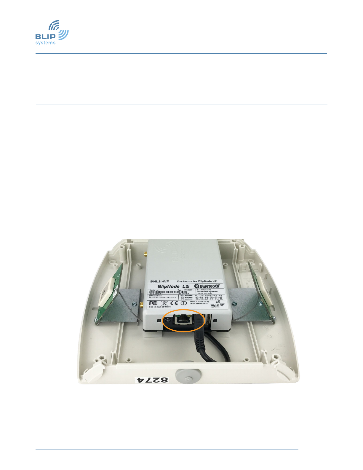
1. If the PoE LAN cable shall enter through the cable entry of the cabinet then feed it
through now.
2. Attach the cable in the LAN slot of the L2i module.
3. As soon as the active PoE LAN cable is attached the unit will be powered and begin
to operate
LAN Cable Plug

Page 8 of 11
08-01-2017
Installation manual
BlipTrack BNL2i-WF v1.1
INSTALLATION MANUAL – BNL2i-WF
STEP 6 - CHECK THE POWER-ON SEQUENCE
The unit is powered on when attaching the PoE LAN cable (The outer green LED will go on).
All four Status LED’s will ash once after approx. 20 sec as part of the basic wake up.
• Then both green Status LED’s will start blinking.
The correct operational status is:
• The inner green LED = On (Connected to BlipServer).
• The outer green LED = Blinking (Power & OS is OK).
• Blue LED = Irrelevant for the Indoor Sensor (No Bluetooth activity).
• Yellow LED = Irrelevant for the Indoor Sensor (No modem).
The unit will try to connect to the BlipServer after the basic wake-up.
The unit is shipped without any BlipServer conguration which is needed for successful
operation. So at this point check that the outer green LED is on when attaching the PoE
LAN cable and that both LED’s will start blinking after the wake up ash.

Page 9 of 11
08-01-2017
Installation manual
BlipTrack BNL2i-WF v1.1
INSTALLATION MANUAL – BNL2i-WF
STEP 7 - FASTEN THE LID AND SIDE PANELS OF THE UNIT
1. Fasten the lid rmly using the four screws.
2. Click the two side panels in place to close the unit. (Be mindful of the green
antennas)
Four screws

Page 10 of 11
08-01-2017
Installation manual
BlipTrack BNL2i-WF v1.1
INSTALLATION MANUAL – BNL2i-WF
STEP 8 - AWAIT UNIT CONFIGURATION
Check that the MAC address of the unit (recorded in “Preparations”stage) can be seen
from the local LAN server.
Blip Support can now provide the needed BlipServer conguration remotely.
1. Contact BLIP Support when the unit is ready for conguration providing the serial
number.
Blip Support will report back when the conguration has been completed.
The unit is now linked to the BlipServer and ready for operation.
MAC Address
Page 11 of 11
08-01-2017
Installation manual
BlipTrack BNL2i-WF v1.1
INSTALLATION MANUAL – BNL2i-WF
STEP 9 - COMPLETE THE INSTALLATION
The unit is now in operation.
1. Take a photo of the mounted unit showing the serial number.
2. Take a photo of the mounted unit in it’s surroundings.
The photos may ease the maintenance phase.
The sensor must be placed at least
1 meter from other radio based
devices.
The sensor shall be placed 3-10
meters above ground level and
have unobstructed view in all
directions.
Table of contents
Popular Accessories manuals by other brands


LINKLITE
LINKLITE A90S user manual

EMX Industries
EMX Industries ColorMax CM1000-1-4 operating instructions

SimPal
SimPal SimPal-T420 user manual

Dometic
Dometic RTX1000 installation manual

Fimar
Fimar HS01 Operation and maintenance manual

Auto Companion
Auto Companion Hot & Cold Portable Electric Cool Box instructions