Carefree of Colorado Installation Manual APEX
.522522-002 7
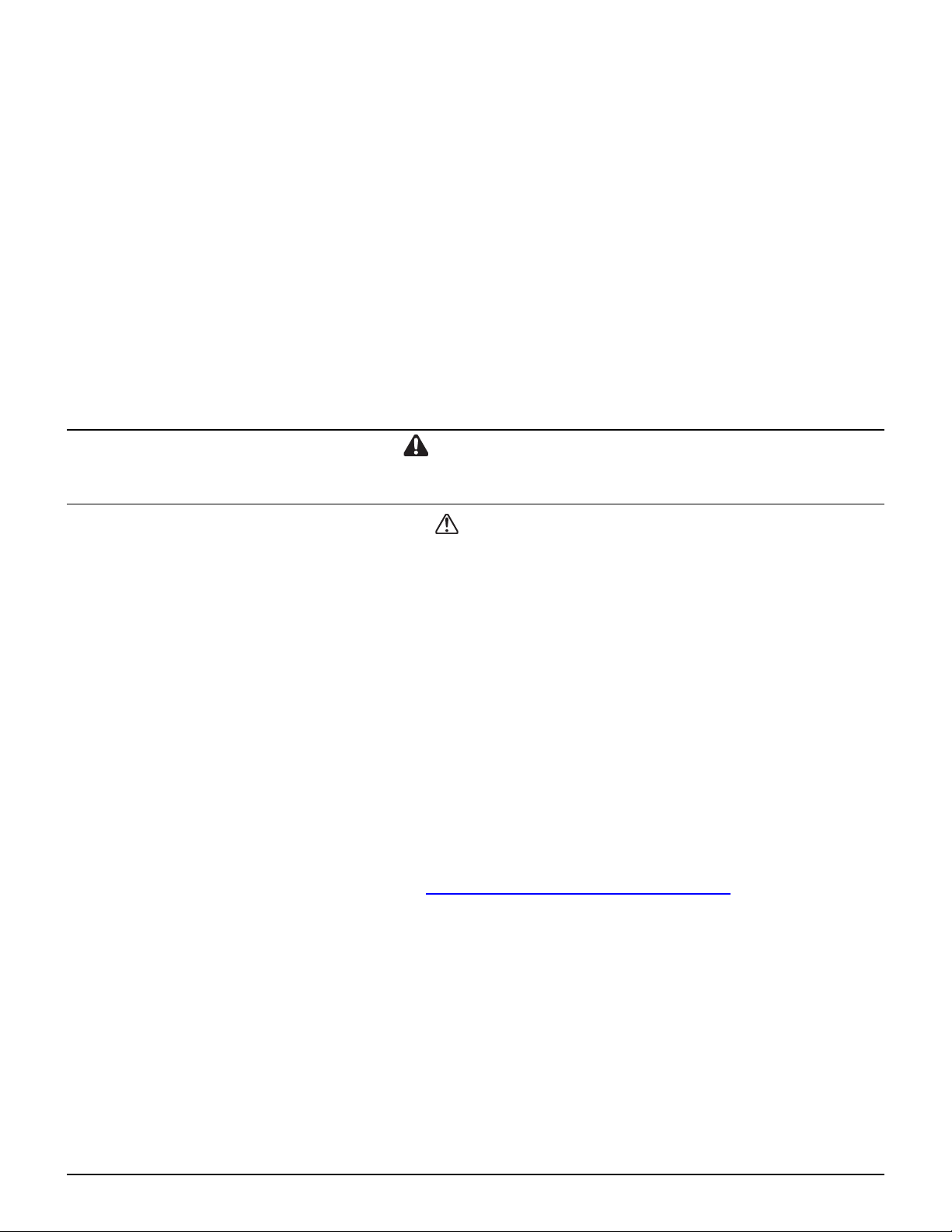
COMPONENT INSTALLATION –SINGLE AWNING
Switch Installation
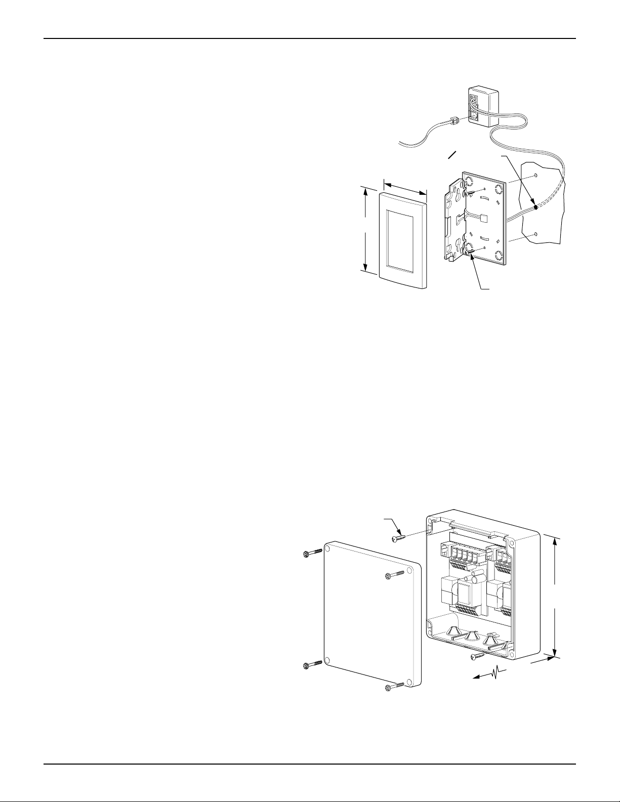
1. At the switch location, cut a rectangular hole 4” x 3
3/4”. The mounting box is able to clamp to
thicknesses from 1/4” to 1”.
2. Insert the mounting box and tighten the latch tab
screws. The tabs will automatically rotate to
clamp on the back side of the mounting surface.
Do not over tighten the clamp screws.
3. Mount the Patio Switch and Wind Speed Switch in
the mounting box.
4. Mount the faceplate onto the switches. It may be
necessary to slightly loosen the switches to align
the faceplate and switches.
5. Connect the switch cable to the patio switch and
route to the location of the control box.
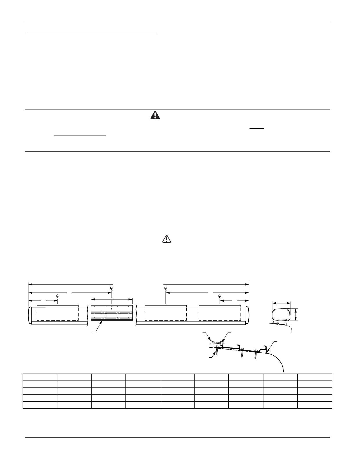
Control Box Installation
(refer to wiring diagram on page 9)
1. Determine the location of the control box.
2. Remove the lid from the control box.
3. Attach the box using a minimum of two (2) #8 x
3/4 screws. The screws must be mounted in
opposite corners.
4. Route a 2-conductor 14AWG NM wire w/
ground from the AC power source to the box. It
is recommended that the installer provide a
dedicated AC circuit that is protected by an
appropriate sized fuse/circuit breaker. Each
patio awning draws a maximum of 3 amps.
Connect wires to the control box as shown in
the wiring diagram on page 11.
5. Splice the awning motor wires to a 3-conductor 14AWG NM wire w/ ground. (Refer to note 1 on the
wiring diagram on page 11)
6. Route the cable wire from the motor to the control box and attach the wires to the terminals as shown.
NOTE: For LH motor configurations:
RED WIRE goes to terminal (1) RED; BLACK WIRE goes to terminal (1) BLACK.
For RH motor configurations:
BLACK WIRE goes to terminal (1) RED: RED WIRE goes to terminal (1) BLACK.
7. Connect the cable from the switch panel to “ACC” in the control box.
8. Connect the cable from the motion sensor to “SHAKE” in the control box.
NOTE: Use the slot cutouts in the box to route the phone cables.
For RF Remote installation, go to page 10.
For optional ignition lock-out installation, go to page 9.
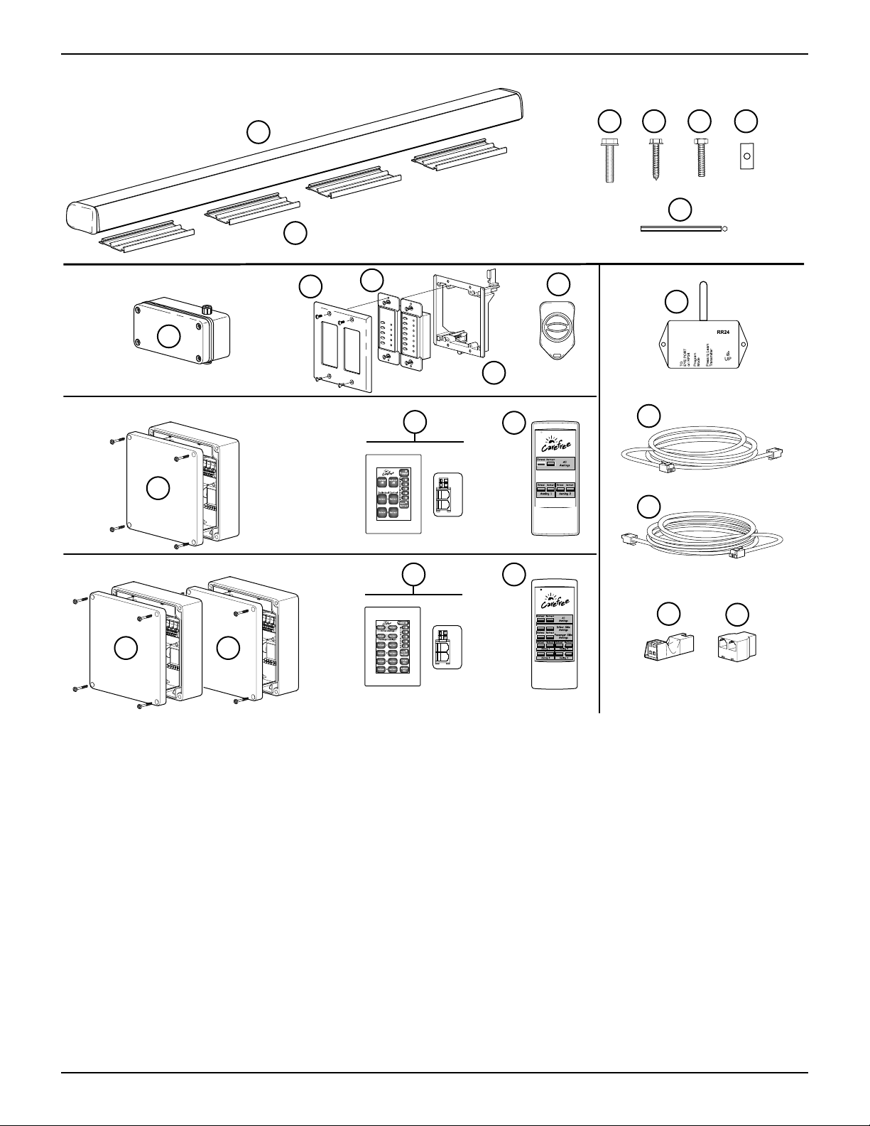
MIRAGE022a
4”
3 3/4”
Face Plate
Wind Speed
Switch
Patio
Switch
Mounting Box
Switch Cable to
Control Box
Latch Tab
Figure 3. Switch Installation.
#8 x 3/4 Screw (2)
RTA033
3”
2 1/2”
6 1/2”
Figure 4. Control Box.