Blue Giant STRONGARM ML10 User manual

OWNER’S MANUAL
STRONGARM™ ML10 VEHICLE RESTRAINT
ISSUE DATE: SEPTEMBER 29, 2014 REV.0 (PART # 038-538E)
WARNING
Do not operate or service this product unless you have
read and fully understand the entire contents of this
manual. Failure to do so may result in property damage,
bodily injury or death.
ACTUAL PRODUCT MAY NOT APPEAR EXACTLY AS SHOWN
STARTING FROM AUGUST, 2013 / SERIAL # 376630

2
STRONGARM™ ML10 VEHICLE RESTRAINT—OWNER’S MANUAL
ISSUE DATE: SEPTEMBER 29, 2014 REV.0 (PART # 038-538E)
TABLE OF CONTENTS
1.0 ABOUT THE STRONGARM™ ML10 WITH OPTIONAL TLC24 CONTROLS 3
1.1 OWNER’S PURCHASE RECORD 3
2.0 INTRODUCTION 4
2.1 WARRANTY INFORMATION 4
2.2 EXCLUSION OF LIABILITY 4
2.3 MANUFACTURER’S NOTE 4
2.4 OWNER’S RESPONSIBILITY 5
3.0 SAFETY MESSAGE COLOR IDENTIFICATION 6
3.1 OPERATIONAL SAFETY WARNINGS 6
4.0 LOCKOUT / TAGOUT PROCEDURE AND RULES 7
5.0 OPERATING INSTRUCTIONS - STANDALONE STRONGARM™ ML10 8
5.1 FUNCTIONAL DESCRIPTION 8
5.2 PRIOR TO USE: EQUIPMENT IN HOME POSITION 9
5.3 TRAILER AT BAY 9
5.4 ENGAGING RESTRAINT 9
5.5 RELEASING THE RESTRAINT ARM 10
6.0 PLANNED MAINTENANCE (PM) CHECK LIST – VEHICLE RESTRAINT – BASED ON CYCLES 11
7.0 RECOMMENDED SPARE PARTS 12
7.1 STANDARD OPERATIONAL COMPONENTS 12
7.2 PROTECTIVE COMPONENTS 13
7.3 TLC24 COMPONENTS (OPTIONAL) 13
8.0 DECAL IDENTIFICATION AND LOCATION 14
9.0 EQUIPMENT COMPONENT ILLUSTRATIONS 15
9.1 COMPONENTS AS SHIPPED CHECK LIST 15
9.2 MECHANICAL ASSEMBLY - 52-011130 16
9.3 GENERAL DIMENSIONS 17
10.0 OPERATING INSTRUCTIONS - STRONGARM™ ML10 WITH TLC24 CONTROLS (AUTOMATIC & MANUAL) 18
10.1 PRIOR TO USE: EQUIPMENT IN HOME POSITION 18
10.2 TRAILER AT BAY 18
10.3 ENGAGING RESTRAINT 19
10.4 RELEASING THE RESTRAINT ARM 19
10.5 MANUAL OVERRIDE MODE (TLC24-A) 20
10.6 TLC24 CONTROLS 21
11.0 OPERATING INSTRUCTIONS - STRONGARM™ ML10 WITH BLUE GENIUS™ CONTROLS 22
11.1 TRAILER AT BAY 22
11.2 ENGAGING RESTRAINT 22
11.3 RELEASING THE RESTRAINT ARM 23
11.4 MANUAL OVERRIDE MODE 23
11.5 BLUE GENIUS™ CONTROLS 24
12.0 EXTERIOR TRAFFIC LIGHT / MIRROR IMAGE SIGN 25
13.0 VEHICLE RESTRAINT TROUBLESHOOTING 26
14.0 WIRING DIAGRAMS 28
14.1 WIRING DIAGRAM—TLC24-A 115V AND 230V SINGLE PHASE 28
14.2 WIRING DIAGRAM—TLC24-M 115V AND 230V SINGLE PHASE 29
14.3 WIRING DIAGRAM— BLUE GENIUS™ 115V SINGLE PHASE 30
3
STRONGARM™ ML10 VEHICLE RESTRAINT—OWNER’S MANUAL
ISSUE DATE: SEPTEMBER 29, 2014 REV.0 (PART # 038-538E)
1.0 ABOUT THE STRONGARM™ ML10 WITH OPTIONAL TLC24 CONTROLS
The manufacturer offers a full line of dock levelers, dock safety equipment, accessories, ergonomic and scissor lift equipment, seals and
shelters, and industrial trucks. Concurrent with a continuing product improvement program, specifications are subject to change without
notice (see section 2.2 of this manual). Please contact the manufacturer for latest information. Some features illustrated may be optional
in certain market areas.
1.1 OWNER’S PURCHASE RECORD
OWNER’S PURCHASE RECORD
Please record information for future inquiries and to validate warranty. (See Section 2.1 for warranty validation)
Dealer: Date in Service:
Number of Units:
Serial Number: Door #:
Serial Number: Door #:
Serial Number: Door #:
Serial Number: Door #:
Serial Number: Door #:
Serial Number: Door #:
Serial Number: Door #:
Serial Number: Door #:
Serial Number: Door #:
The StrongArm™ ML10 Mechanical Vehicle Restraint is a high-performance yet low-cost solution for loading docks worldwide. With a
vertical restraining range of 11" to 26" (279 mm to 660 mm) above ground and horizontal reach of 13" (330 mm), the ML10 is compatible
with virtually all modern trucks and trailers, even those with air-ride suspension systems. 30,000 lb (13,636 kg) of restraining force
prevents premature truck departure during loading and unloading. Easy and ergonomic to operate, the unit is engaged and released by
a single detachable control rod.
This manual also incorporates operating instructions for the TLC24-A (automatic) and TLC24-M (manual) lights communication
packages, which are optional and recommended add-ons to the ML10. Both control stations feature a keyed selector switch, red and
green indicator lights, high-visibility LED traffic lights, and mirror-image driver warning signs.
See section 8.0 Decal Identification and Location, item #4 for serial number location.
NOTICE

4
STRONGARM™ ML10 VEHICLE RESTRAINT—OWNER’S MANUAL
ISSUE DATE: SEPTEMBER 29, 2014 REV.0 (PART # 038-538E)
2.0 INTRODUCTION
The following is a quick reference to important procedures that
must be followed while using the Vehicle Restraint System. It is
not intended to cover, or suggest that it does cover, all procedures
necessary to ensure safe operation. All operators should be aware
of and abide by all workplace safety regulations applicable to
the operation of the Vehicle Restraint System. These laws and
regulations include but are not limited to:
• TheOccupationalSafetyandHealthAct
• CanadaOccupationalHealthandSafetyRegulations
• Occupational Safety and Health Acts for Individual States
(USA)
For additional information on these regulations as well as industry
standards that may apply to this product, please contact:
American National Standards Institute (ANSI)
1430 Broadway
New York, NY 10018
Telephone: 212.642.4900
www.ansi.org
Also a member of:
Loading Dock Equipment Manufacturers
A Product Section of Material Handling Industry of America
A Division of Material Handling Industry
8720 Red Oak Blvd, Suite 201
Charlotte, NC, 28217-3992
Telephone: 704.676.1190
www.mhi.org/lodem
2.2 EXCLUSION OF LIABILITY
The manufacturer assumes no liability for damage or injury to
persons or property which occur as a result of defects or faults in
or incorrect use of the Vehicle Restraint System. The manufacturer
also assumes no liability for lost profits, operating downtimes, or
similar indirect losses incurred by the purchaser. Injury to third
parties, irrespective of its nature, is not subject to compensation.
The manufacturer reserves the right to make changes at any time
to the modules, components, and accessories, concurrent with
its continuing product improvements and development program.
Specifications, operating instructions, and illustrations included in
this manual are subject to change without notice. Please contact
manufacturer for the latest information.
2.3 MANUFACTURER’S NOTE
The Vehicle Restraint has been carefully inspected and tested at
the manufacturer’s plant prior to shipment, but should be checked
upon receipt for transport damage. Any observed transport
damage is to be listed on the signed copy of the freight document.
Notify the freight forwarder of any damage WITHIN 48 HOURS.
2.1 WARRANTY INFORMATION
Thank you for purchasing Blue Giant products. We appreciate your
business, and are confident that our product will serve you for
many years to come. In the event that you experience a problem
with our product, our Warranty Center is here to support the
Blue Giant Product(s) that you have purchased.
To validate warranty on recently purchased equipment,
please complete and submit your information with our
online Warranty Registration at www.BlueGiant.com.
For more information about Blue Giant Warranty Support, please
contact your local Blue Giant Equipment dealer, representative or
authorized partner near you. You may also visit www.BlueGiant.
com or phone 1.905.457.3900.
DEALER INFORMATION
Name:
Contact:
Telephone:
* NOTE that failure to validate warranty at the time of receipt can
seriously affect the outcome of any claim.

5
STRONGARM™ ML10 VEHICLE RESTRAINT—OWNER’S MANUAL
ISSUE DATE: SEPTEMBER 29, 2014 REV.0 (PART # 038-538E)
2.4 OWNER’S RESPONSIBILITY
1. The owner should recognize the inherent danger of the
interface between the dock and the freight carrier. The owner
should, therefore, train and instruct operators in the safe use
of the dock equipment and accessories in accordance with the
manufacturer’s recommendations.
2. The owner should thoroughly familiarize themselves with
the following procedures and specifications, and request
immediate replacement of all manufacturer-supplied
documents that are missing, damaged, or otherwise illegible.
• Installationinstructions
• Operatinginstructions
• Plannedmaintenanceprocedures
• Inspectionsprocedures
• Replacementpartslists
Upon receipt of any newly purchased dock equipment, the
owner shall verify the presence of owner’s manuals, operating
placards, and any other documentation necessary for
training dock personnel how to use the equipment safely and
effectively.
3. Manufacturer’s recommended periodic maintenance and
inspection procedures shall be followed, and written records
of the performance of these procedures should be kept as per
warranty guidelines.
4. Dock equipment that is structurally damaged, experiencing
performance irregularities, or has been potentially
compromised (i.e. sudden loss of support due to premature
truck departure) shall be removed from service until a trained
and authorized manufacturer’s representative can conduct an
inspection and perform any necessary repairs.
5. As with any piece of machinery, dock equipment requires
routine maintenance, lubrication, and adjustments. Your
local Blue Giant®representative offers owners the option
of a Planned Maintenance Program (P.M.P.). As part of this
service, your local Blue Giant®representative will do all routine
maintenance, lubrication, and adjustments.
6. The owner shall ensure that all nameplates, caution/
instruction markings or labels are in place and legible, and
that the appropriate operating/maintenance manuals are
provided to authorized users. Replacement name plates,
caution/instruction labels, and manuals containing operating
and maintenance instructions are available through the
Blue Giant Aftermarket Department.
7. Modifications or alterations of dock equipment shall be made
only with written permission of the original manufacturer. These
changes shall also satisfy all safety recommendations of the
original equipment manufacturer for the particular application
of the dock equipment.
8. The owner or a trained and authorized representative shall
verify that all freight carrier brakes have been applied and a
vehicle restraint and/or wheel chocks properly engaged before
cross-docking procedures such as loading and unloading
begin.
9. Unless specifically agreed to in writing by Blue Giant
Equipment Corporation at the time of order (and prior to
manufacture), all Blue Giant Dock equipment is sold as a
complete offering, and must not be altered or added to in
any manner (which includes configuration and function)
without written permission from an authorized manufacturer’s
representative.
10. If, at the request of the owner, Blue Giant does not supply
all or some of the dock equipment power unit and/or control
station components, the owner shall assume responsibility for
any and all operational and safety issues associated with the
resulting configuration.

PELIGRO
6
STRONGARM™ ML10 VEHICLE RESTRAINT—OWNER’S MANUAL
ISSUE DATE: SEPTEMBER 29, 2014 REV.0 (PART # 038-538E)
DANGER
DANGER
DANGER
DANGER
3.0 SAFETY MESSAGE COLOR IDENTIFICATION
This manual includes color-coded safety messages that clarify instructions and specify areas where potential hazard exists. To prevent
the possibility of equipment damage and serious injury or death, please observe strictly the instructions and warnings contained in
the messages. If warning decals become damaged or missing, replace them immediately. Avoid accidents by recognizing dangerous
procedures or situations before they occur.
Serious injury or death will likely occur if the
instructions are not followed.
Serious injury or death may occur if the
instructions are not followed.
Procedures marked notice must be followed in order
to prevent damage to machinery.
Instructions marked caution concern safe operating procedure.
Failure to comply may result in personal injury.
3.1 OPERATIONAL SAFETY WARNINGS
1. Installation must be performed only by trained and authorized personnel.
2. Prior to installation, place adequate barriers to prevent vehicle traffic from entering the work area.
3. During installation, anchors must be properly torqued to achieve the necessary anchoring strength. DO NOT USE IMPACT DRIVERS.
4. Any electrical work must be performed by qualified personnel only.
5. Do not remove the wheel chocks until loading /unloading is finished and the truck is cleared for departure or the vehicle restraint has been
released and the lights have changed to RED inside and GREEN outside.
WARNING
DANGER 1. Do not operate the dock equipment while anyone is standing in its path.
2. Lift the dock equipment with suitable hoisting equipment only. Do not
stand under the dock equipment or any heavy object while it is being
hoisted.
3. BEFORE BEGINNING ANY SERVICE PROCEDURES:
Disconnect the power and follow all lockout / tagout procedures outlined
in this manual.
Keep hands and feet away from operating space of the
restraint apparatus.
CRUSH
HAZARD
1. Only trained personnel should operate or service this equipment.
2. Do not operate the dock equipment until the transport vehicle is parked against the dock bumpers.
3. Always park the dock equipment after use.
4. Conduct routine inspections and maintenance. Failure to do so could cause equipment damage and or personal injury.
5. Always call your authorized service representative or manufacturer immediately if a malfunction occurs.
6. Always return the restraint arm to the parked position after use.
1. Do not ground welding equipment to any electrical components.
2. Do not allow the drill to go too deeply into the control box, as damage may occur to the control systems.
3. Never use air to blow debris from the control box. Use a vacuum to perform any necessary cleaning.
4. Do not connect green ground lead into control box or junction box until all welding has been completed.
5. If an extension plate / box is required, securely mount it on the restraint with hardware provided before shimming and drilling.
6. Improper adjustments and / or lubrication may cause operational problems with equipment.
DANGER NOTICE
CAUTIONWARNING
DANGER
NOTICE
CAUTION
1. Installation must be performed only by trained and authorized personnel.
2. Prior to installation, place adequate barriers to prevent vehicle traffic from entering the work area.
3. During installation, anchors must be properly torqued to achieve the necessary anchoring strength. DO NOT USE IMPACT DRIVERS.
4. Any electrical work must be performed by qualified personnel only.
5. Do not remove the wheel chocks until loading /unloading is finished and the truck is cleared for departure or the vehicle restraint has been
released and the lights have changed to RED inside and GREEN outside.

XXXXXXXXXXXX
XXXXXXXXXXX
OPERATE
DO NOT
7
STRONGARM™ ML10 VEHICLE RESTRAINT—OWNER’S MANUAL
ISSUE DATE: SEPTEMBER 29, 2014 REV.0 (PART # 038-538E)
WARNING
Always lockout and tagout any power source before performing any
work on any electrical devices or electrical controls according to
OSHA regulations and approved local electrical codes.
Approved way to lockout / tagout.
4.0 LOCKOUT / TAGOUT PROCEDURE AND RULES
In accordance with the rules and regulations of the Occupational
Safety and Health Administration (OSHA), all affected employees
must be notified that the machine or equipment will be shut down
and locked out to perform repair or maintenance work. The work
area must be checked to ensure that all personnel have been
removed or safely repositioned. The machine or equipment power
supply shall be locked in the OFF position or disconnected from
the energy source. Blue Giant® strongly recommends that only
OSHA-approved lockout devices and procedures be utilized.
The energy isolating device must bear a prominent warning tag
indicating that work is being done on the equipment and the
name of the authorized employee responsible for the lockout. It is
mandatory that tagout notices not be susceptible to deterioration
or illegibility due to weather conditions or exposure to chemicals
and moisture.

8
STRONGARM™ ML10 VEHICLE RESTRAINT—OWNER’S MANUAL
ISSUE DATE: SEPTEMBER 29, 2014 REV.0 (PART # 038-538E)
5.0 OPERATING INSTRUCTIONS - STANDALONE STRONGARM™ ML10
ML10 operation placard—part # 038-759E.
WARNING
5.1 FUNCTIONAL DESCRIPTION
The StrongArm™ ML10 mechanical vehicle restraint is used to
restrain a trailer at the loading dock. When engaged, it secures
a vehicle’s under-ride guard (ICC bar), restricting forward
movement caused by vehicle creep or unscheduled departure.
It is mechanically engaged and disengaged using a control rod
(782-371). For added safety, Blue Giant recommends the use
of a lights communication package (TLC24-A or TLC24-M) in
conjunction with the ML10.
Do not operate this vehicle restraint unless you have been trained and
authorized to do so, and have read and understood all of the safety
information and instructions contained in this manual.
Do not operate this restraint until you have checked its condition.
Report the need for repairs to your supervisor immediately and do not
operate the unit until repairs are made.
Never try to lift or move any part of the vehicle restraint manually. Keep
hands and feet clear of vehicle restraint pinch points.
It is the responsibility of the owner / operator of truck / vehicle to
(whenever possible) exhaust the air from air-ride suspension systems
prior to performing loading or unloading.
Because ICC bars differ in strength and construction, review the need
to use wheel chocks in conjunction with the vehicle restraint.
This vehicle restraint is designed for rear impact guards (RIG)
and rear impact protection (ICC Bar) that follow the Federal
Motor Carrier Safety Administration guidelines (FMCSA
section 571.223 and 571.224) + NHTSA (National Highway
Traffic Safety Administration) guidelines.
Truck / Vehicle Dock Bumper Dock Leveler (Typical)
Vehicle
ICC Bar Dock Face
Vehicle Restraint
(Arm Released)
WARNING
TLC24-A TLC24-M
OUTSIDE TRAFFIC
LIGHT STATUS
INSIDE COMMUNICATION
LIGHTS & CONTROL STATION
ENGAGE RESTRAINT
Activate the ML10 by using the control rod to
press down on the engagement arm until the
restraint arm is in the fully vertical position,
holding the ICC bar in place.
TLC24-A: The control station light will turn
GREEN and the outside trafc light will turn
RED.
TLC24-M: Turn the key switch to the
‘Interlocked’ position (green LED). The
outside trafc light changes to RED while
GREEN light on the control station comes on.
TLC24-A TLC24-M
OUTSIDE TRAFFIC
LIGHT STATUS
INSIDE COMMUNICATION
LIGHTS & CONTROL STATION
OPPOSITE
SIDE
NOTE: The truck / trailer is NOT restrained if the arm is not fully vertical and
the communication lights do not change colour as described above. Do a visual
inspection to conm that the ICC bar is securely restrained before proceeding with
loading / unloading.
OPERATING INSTRUCTIONS
Only for the ML10 and TLC24-A (Automatic) or TLC24-M (Manual)
1. Only trained and authorized personnel may operate this vehicle
restraint.
2. Read, understand, and follow the instructions on this document and
included manual
3. Prior to using the vehicle restraint:
• Ensure that the vehicle restraint is free and clear of all debris, snow,
and ice.
• Ensure that all personnel near the vehicle restraint are aware that it
is being operated.
• Operate the vehicle restraint through one complete cycle to conrm
that it is functioning properly. If the vehicle restraint is equipped with
a communications package, conrm that the lights are working as
required.
• Inspect unit for signs of structural damage or mechanical
malfunction. If damage is observed or the restraint fails to operate
properly, remove it from service and notify maintenance personnel
immediately.
4. Before attempting to restrain a transport vehicle:
• Ensure that the vehicle is parked rmly against the dock bumpers.
• If the dock leveler is equipped with a light communication package,
load and unload on green only.
• Do not exceed the rated capacity as indicated on the serial plate.
• Do not leave equipment or material unattended on the dock leveler.
• Keep a safe distance from both edges.
• If either the dock leveler or vehicle restraint fail to operate as
outlined in the accompanying manual’s operating instructions, refer
to the Troubleshooting section.
5. If service or maintenance is required:
• Only authorized service personnel shall maintain or service the
units.
APPLIES TO ALL DOCK LEVELER AND VEHICLE RESTRAINT
COMBINATIONS
RELEASE RESTRAINT
After loading / unloading has been completed
and the dock leveler is safely parked, release
the restraint arm by pulling up on it quickly
and rmly using the control rod. The arm will
return to the parked position.
TLC24-A: The control station light will turn
RED and the outside trafc light will turn
GREEN.
TLC24-M: Turn the key switch to the ‘No
Trafc’ position (red LED). The outside trafc
light changes to GREEN and the control
station light turns RED.
038-759Ewww.BlueGiant.com
NOTE: If the ICC bar is applying pressure to the restraint arm, it may be necessary
to have the driver back up the vehicle before releasing the arm.
9
STRONGARM™ ML10 VEHICLE RESTRAINT—OWNER’S MANUAL
ISSUE DATE: SEPTEMBER 29, 2014 REV.0 (PART # 038-538E)
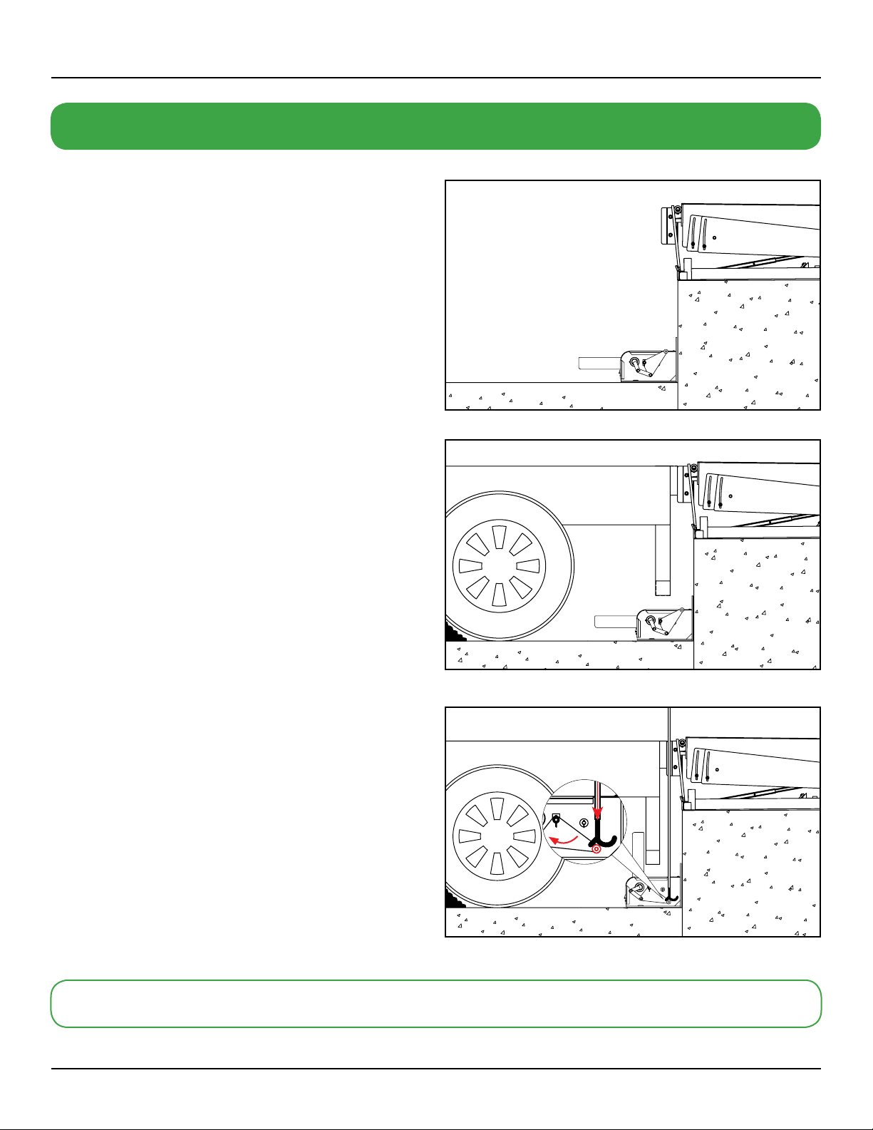
5.3 TRAILER AT BAY
The truck reverses into position against the dock leveler bumpers.
After the truck is correctly parked, chock wheels securely.
STANDARD OPERATION PROCEDURES
5.4 ENGAGING RESTRAINT
Activate the ML10 by using the control rod (Blue Giant part
# 782-371) to press down on the engagement arm until the
restraint arm is in the fully vertical locked position, which now
holds the ICC bar in place.
NOTE: The truck / trailer is NOT restrained if the arm is not fully
vertical. Do a visual inspection to confirm that the ICC bar is
securely restrained before proceeding with loading / unloading.
RESTRAINT
ARM IN HOME
POSITION
5.2 PRIOR TO USE: EQUIPMENT IN HOME
POSITION
The restraint apparatus is in the home position and the dock leveler
lip is parked safely in the lip keepers.
PERFORM LOADING AND UNLOADING
10
STRONGARM™ ML10 VEHICLE RESTRAINT—OWNER’S MANUAL
ISSUE DATE: SEPTEMBER 29, 2014 REV.0 (PART # 038-538E)
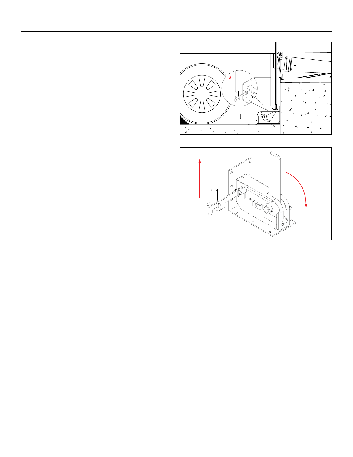
5.5 RELEASING THE RESTRAINT ARM
After loading / unloading has been completed and the dock leveler
is safely parked, release the restraint arm by pulling up on it quickly
and firmly using the control rod (Blue Giant part # 782-371). The
arm will return to the parked position.
NOTE: If the ICC bar is applying pressure to the restraint arm, it
may be necessary to have the driver back up the vehicle before
releasing the arm.
Control rod (part # 782-371) releasing the restraint arm.
11
STRONGARM™ ML10 VEHICLE RESTRAINT—OWNER’S MANUAL
ISSUE DATE: SEPTEMBER 29, 2014 REV.0 (PART # 038-538E)
INSPECTED BY: DATE:
Forward checklist to the person responsible for Vehicle Restraint maintenance.
6.0 PLANNED MAINTENANCE (PM) CHECK LIST – VEHICLE RESTRAINT – BASED ON CYCLES
INSTRUCTIONS FOR USE: Photocopy this page and indicate “OK for USE” with a check mark in the appropriate box of each
inspection point.
EVERY DAY:
Remove any debris that may have accumulated inside the restraint.
Check that the operating hazards placard is present and legible.
Verify complication-free operation of the restraint and the interior and exterior lights system.
Check for missing or damaged dock bumpers.
Verify complication-free operation of the TLC24-A / TLC24-M and exterior lights (if applicable).
EVERY THREE MONTHS:
Lubricate all bushings.
Check wall or floor anchors.
Check safety warning decals and replace if necessary.
Explain faults briefly in the space provided below:
DANGER WARNING
DANGER
DANGER
Prior to repairs, place adequate barriers to prevent unauthorized
personnel and vehicle traffic from entering the work area.
All repairs and maintenance work are to be conducted by trained
and authorized personnel ONLY.
When repairing or conducting maintenance procedures on electrical components, perform lockout / tagout steps according to OSHA
regulations and approved electrical codes.
8
5
46
7 9
1 2 3
12
STRONGARM™ ML10 VEHICLE RESTRAINT—OWNER’S MANUAL
ISSUE DATE: SEPTEMBER 29, 2014 REV.0 (PART # 038-538E)
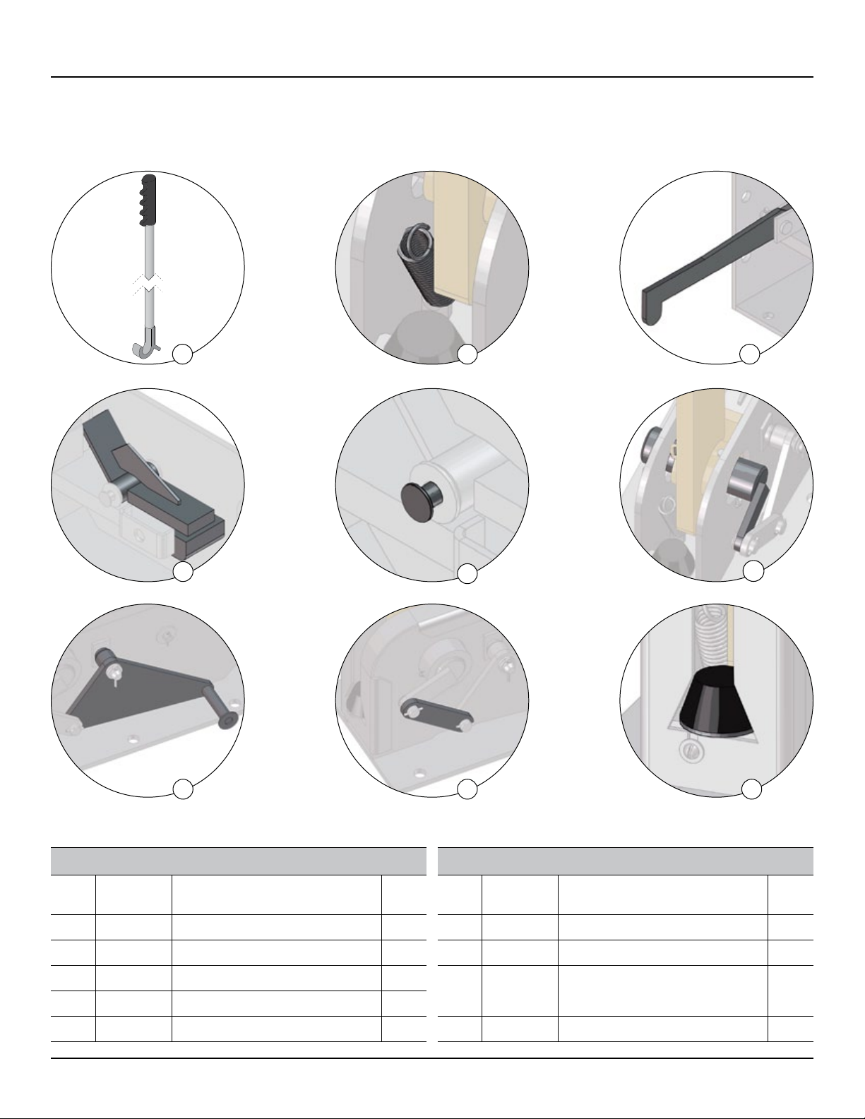
7.0 RECOMMENDED SPARE PARTS
7.1 STANDARD OPERATIONAL COMPONENTS
RSP FOR ML10 – STD OPERATIONAL COMPONENTS
ITEM
NO. PART NO. DESCRIPTION QTY
REQ’D
1 782-371 Control Rod 1
2 017-012 Return Spring 1
3 522-0000 Arm, Release Lever 1
4522-5001 Lock Weldment 1
5 210-0005 Pin, Lock Weldment 1
RSP FOR ML10 – STD OPERATIONAL COMPONENTS
ITEM
NO. PART NO. DESCRIPTION QTY
REQ’D
6 522-5005 Arm, Pivot Shaft Assembly 1
7 522-5006 Arm, Engagement Lever 1
8 522-0010 Arm Engagement Link
1 1/4" x 5 5/8" (32mm x 143 mm) 1
9 091-041 Bumper 1

3
6
4 5
1 2
10
13
STRONGARM™ ML10 VEHICLE RESTRAINT—OWNER’S MANUAL
ISSUE DATE: SEPTEMBER 29, 2014 REV.0 (PART # 038-538E)
7.2 PROTECTIVE COMPONENTS
RSP FOR ML10 – PROTECTIVE COMPONENTS
ITEM NO. PART NO. DESCRIPTION QTY
REQ’D
10 52-011187 Top Cover 1
7.3 TLC24 COMPONENTS (OPTIONAL)
RSP FOR TLC24
ITEM
NO. PART NO. DESCRIPTION QTY
REQ’D
4 026-G206 24V Monoblock LED Indicator- Green 1
5026-G014-
1115
Traffic Lights Controller Board
(1PH 115V TLC) 1
6026-G014-
1230
Traffic Lights Controller Board
(1PH 230V TLC) 1
RSP FOR TLC24 COMPONENTS (OPTIONAL)
ITEM
NO. PART NO. DESCRIPTION QTY
REQ’D
1 026-G202 Normal-Open Contact Block 1
2 026-G203 Normal-Closed Contact Block 1
3 026-G205 24V Monoblock LED
Indicator- Red 1

BLUE GIANT EQUIPMENT
CORPORATION
MODEL/
MODELO
SERIAL NO./
NO. DE SERIE
TEST LOAD/
PRUEBA DE CARGA
MFG / FAB
COMPLIES WITH ANSI MH30.3
“REFER TO SAFETY AND OPERATING
INSTRUCTIONS IN YOUR OWNERS
MANUAL” /
“A SEGURESE DE HABER LEIDO LAS
PROVISIONES DE OPERACION Y
SEGURIDAD EN EL MANUAL DEL
PROPIETANO.”
lbs.
kg.
www.BlueGiant.com
MADE IN CANADA
HECHO EN CANADA
038-299ES
ML10
371381
01/14
22,500
10,206
(MM / YYYY)
3
4
038-240
VehicleRestraint
1
1
2
4
3
2
14
STRONGARM™ ML10 VEHICLE RESTRAINT—OWNER’S MANUAL
ISSUE DATE: SEPTEMBER 29, 2014 REV.0 (PART # 038-538E)
ITEM # QTY PART NO. DESCRIPTION
1 1 038-859E Decal - BG StrongArm™ ML10
2 1 038-240 Decal - StrongArm™ - Vehicle Restraint
3 1 038-243E Decal - Crush Hazard
4 1
038-299EF Decal - Serial Plate - English / French
038-299ES Decal - Serial Plate - English / Spanish
8.0 DECAL IDENTIFICATION AND LOCATION
Keep Hands and Feet away
from operating space of the
Restraint Arm. CRUSH HAZARD
038-243E
CAUTION
3
1‡
2*
5
4
15
STRONGARM™ ML10 VEHICLE RESTRAINT—OWNER’S MANUAL
ISSUE DATE: SEPTEMBER 29, 2014 REV.0 (PART # 038-538E)
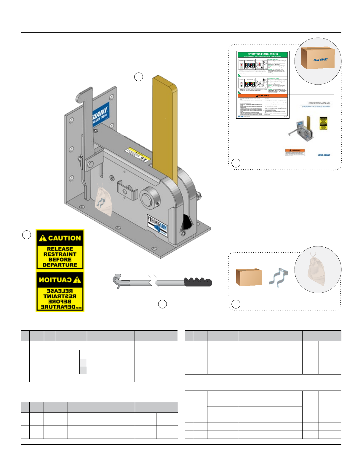
9.0 EQUIPMENT COMPONENT ILLUSTRATIONS
9.1 COMPONENTS AS SHIPPED CHECK LIST
MOUNTING
BRACKET
‡ NOTE: The arm is shown in the shipping
position and will need to be installed correctly.
ANCHORS
ITEM QTY PART NO. DESCRIPTION APPROX. WEIGHT
1 1 52-011130 ML10 Body 150 lb 68 kg
2 1 038-224/5
EExterior Driver Warning
Sign (English / French /
Spanish)
0.7 lb 0.32 kgF
S
3 1 782-371 Control Rod 7 lb 3.2 kg
ITEM # 5 - CONTROLS (OPTIONAL)
1
TLC24-A
See Sec 10.0
Automatic Lights Communication
Package (optional)
5 lb 2.27 kg
TLC24-M
See Sec 10.0
Manual Lights Communication
Package (optional)
1032-461 Exterior Traffic Light (optional) 1.3 lb 0.6 kg
1038-759E Operation Placard — —
ITEM # 4 - HARDWARE INCLUDED:
QTY PART NO. DESCRIPTION APPROX. WEIGHT
6010-108 5/8" dia. x 6" / 152mm Anchor
Wedge .15 lb .06 kg
1035-288 Mounting Bracket — —
ITEM # 5 - COMPONENTS
QTY PART NO. DESCRIPTION APPROX. WEIGHT
1038-538E ML10 Owner's Manual — —
1038-759E Operation Placard — —
OPTIONAL
CONTROLS
*NOTE: For sign specifications, see section 7.7
WARNING
TLC24-A TLC24-M
OUTSIDETRAFFIC
LIGHTSTATUS
INSIDECOMMUNICATION
LIGHTS& CONTROL STATION
ENGAGE RESTRAINT
Activate the ML10 by using the control rod to
press down on the engagement arm until the
restraint arm is in the fully vertical position,
holding the ICC bar in place.
TLC24-A: The control station light will turn
GREEN and the outside trafc light will turn
RED.
TLC24-M: Turn the key switch to the
‘Interlocked’ position (green LED). The
outside trafc light changes to RED while
GREEN light on the control station comes on.
TLC24-A TLC24-M
OUTSIDETRAFFIC
LIGHTSTATUS
INSIDECOMMUNICATION
LIGHTS& CONTROL STATION
OPPOSITE
SIDE
NOTE: The truck / trailer is NOT restrained if the arm is not fully vertical and
the communication lights do not change colour as described above. Do a visual
inspection to conm that the ICC bar is securely restrained before proceeding with
loading / unloading.
OPERATING INSTRUCTIONS
Only for the ML10 and TLC24-A (Automatic) or TLC24-M (Manual)
1. Only trained and authorized personnel may operate this vehicle
restraint.
2. Read, understand, and follow the instructions on this document and
included manual
3. Prior to using the vehicle restraint:
• Ensure that the vehicle restraint is free and clear of all debris, snow,
and ice.
• Ensure that all personnel near the vehicle restraint are aware that it
is being operated.
• Operate the vehicle restraint through one complete cycle to conrm
that it is functioning properly.If the vehicle restraint is equipped with
a communications package, conrm that the lights are working as
required.
• Inspect unit for signs of structural damage or mechanical
malfunction. If damage is observed or the restraint fails to operate
properly,remove it from service and notify maintenance personnel
immediately.
4. Before attempting to restrain a transport vehicle:
• Ensure that the vehicle is parked rmly against the dock bumpers.
• If the dock leveler is equipped with a light communication package,
load and unload on green only.
• Do not exceed the rated capacity as indicated on the serial plate.
• Do not leave equipment or material unattended on the dock leveler.
• Keep a safe distance from both edges.
• If either the dock leveler or vehicle restraint fail to operate as
outlined in the accompanying manual’s operating instructions, refer
to the Troubleshooting section.
5. If service or maintenance is required:
• Only authorized service personnel shall maintain or service the
units.
APPLIES TO ALLDOCK LEVELER AND VEHICLE RESTRAINT
COMBINATIONS
RELEASE RESTRAINT
After loading / unloading has been completed
and the dock leveler is safely parked, release
the restraint arm by pulling up on it quickly
and rmly using the control rod. The arm will
return to the parked position.
TLC24-A: The control station light will turn
RED and the outside trafc light will turn
GREEN.
TLC24-M: Turn the key switch to the ‘No
Trafc’ position (red LED). The outside trafc
light changes to GREEN and the control
station light turns RED.
038-759Ewww.BlueGiant.com
NOTE: If the ICC bar is applying pressure to the restraint arm, it may be necessary
to have the driver back up the vehicle before releasing the arm.
1 611222120 1612
4
3
25
23
18
18
26
27
19
24
20 21
7
8
13
5
17
2
14
15
9
10
23
29
28
16
STRONGARM™ ML10 VEHICLE RESTRAINT—OWNER’S MANUAL
ISSUE DATE: SEPTEMBER 29, 2014 REV.0 (PART # 038-538E)
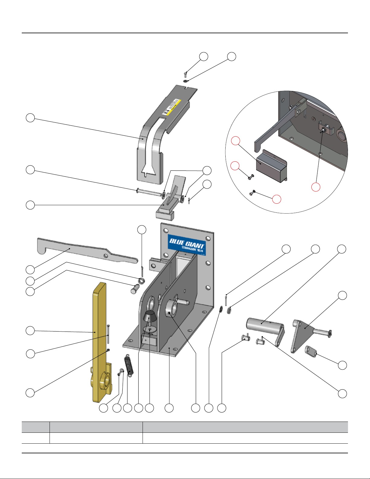
9.2 MECHANICAL ASSEMBLY - 52-011130
OPTIONAL: AUTOMATIC LIGHT PACKAGE
NOTE PART NO. DESCRIPTION
52-011131 Automatic light package includes parts highlighted
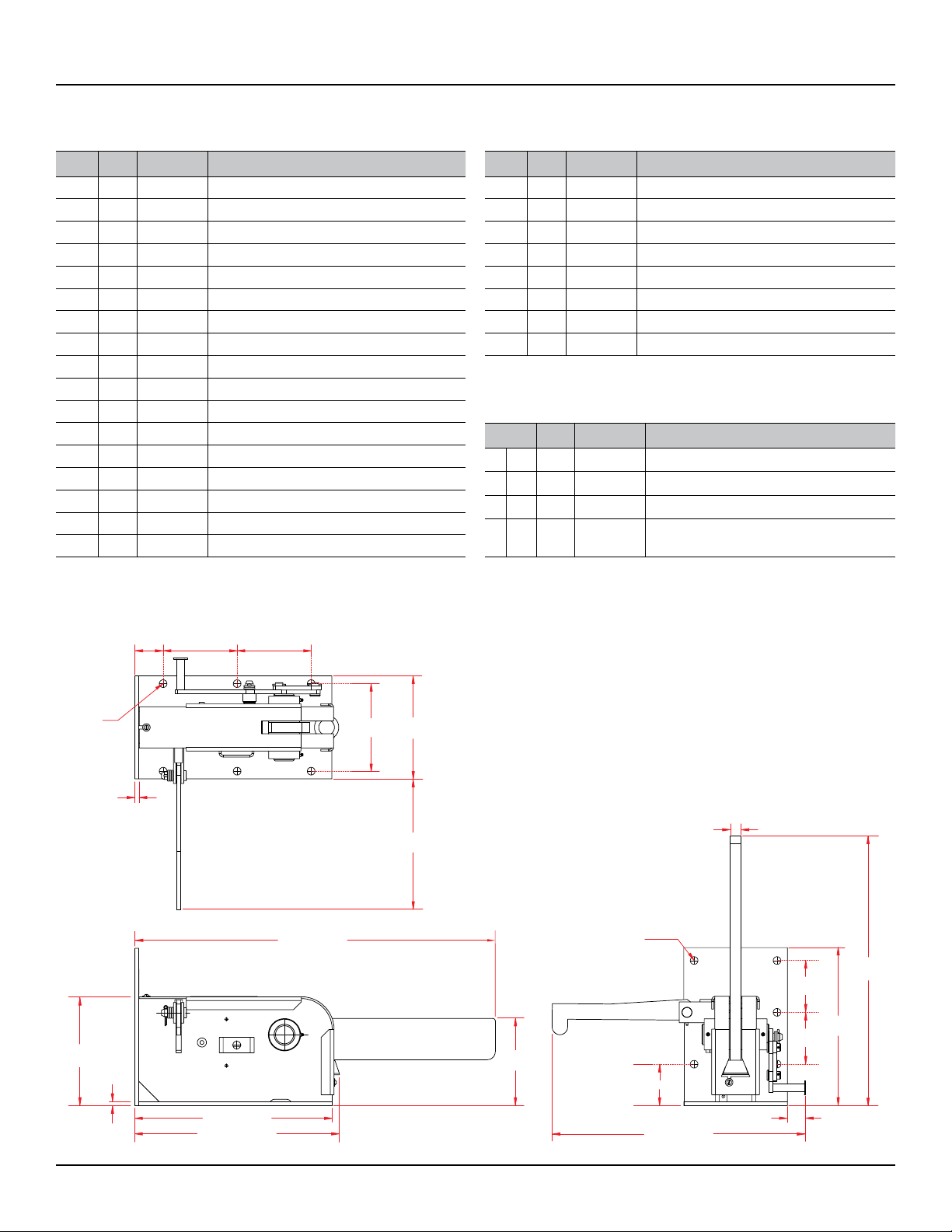
8 3/8"
(213mm)
10 1/2"
(267mm)
19 13/16" (503mm)
19 1/8" (486mm)
3/8"
(10mm)
33 5/8" (854mm)
15 1/4"
(387mm)
26"
(660mm)
5"
(127mm)
4" (101mm)
1" (25.4mm)
24.3" (618mm)
6 x 3/4" Ø
(19mm)
5"
(127mm)
10"
(254mm)
8 1/2"
(216mm)
12 3/4"
(323mm)
3/8"
(10mm)
2 3/4"
(70mm)
7 3/16"
(183mm)
6 x 3/4" Ø
(19mm)
7 3/16"
(183mm)
1 1/2"
(38mm)
17
STRONGARM™ ML10 VEHICLE RESTRAINT—OWNER’S MANUAL
ISSUE DATE: SEPTEMBER 29, 2014 REV.0 (PART # 038-538E)
9.2 MECHANICAL ASSEMBLY - 52-011130
AUTOMATIC LIGHT PACKAGE MECHANICAL
ASSEMBLY - 52-011131 (INCLUDES PART # 52-011130)
ITEM QTY PART NO. DESCRIPTION
18 2 013-025 Cotter Pin 3/16" x 1 ½" (38mm)
19 1 013-018 Cotter Pin 3/32" x 1" (25mm)
20 2 011-020 Round Head Slotted Screws (U.S.)
21 2 012-211 Flat Washer Type B Narrow 3/8"
22 1 017-012 Tension Spring
23 5 106-046 Ring, Split
24 3 012-212 Washer, Zinc-Plated ½"
25 1 105-879 Flat Washer ¾" x 1-3/16" x 1/16"
ITEM QTY PART NO. DESCRIPTION
26 1 52-011115 Sensor Cover
27 2 010-036 Cap Screw 5/16-18 x 1/2 HH GR. 5 ZC
28 2 012-200 Spring Lock Washers 5/16"
29 1 028-212 Proximity Sensor 18mm w/ 5m cable + 2
jamb nuts
ITEM QTY. PART NO. DESCRIPTION
1 1 52-011160 Body Weldment
2 1 52-012731 Restraint Arm 26" (660mm)
3 1 522-5005 Shaft Arm Pin
4 1 522-5006 Engagement Arm Weldment
5 1 522-0010 Actuator Linkage
6 2 119-278 Pivot Pin
7 1 522-5001 Lock Weldment
8 1 210-0005 Lock Roller Pin Assembly
9 1 522-0000 Release Arm
10 1 107-196 Clevis Pin
11 1 107-046 Washer Spacer
12 1 091-041 Rubber Bumper
13 1 52-011187 Truck Latch Cover
14 1 011-141 Cap Screw ¼" - 20 x 3 ½"(89mm) HH
15 1 011-506 Nuts Hex ¼" - 20 PLTD
16 2 019-500 Nipple Straight Grease ¼"
17 2 013-066 5/32" dia. Spring Pin 5/32" x 1 1/4" (32mm)
9.3 GENERAL DIMENSIONS
18
STRONGARM™ ML10 VEHICLE RESTRAINT—OWNER’S MANUAL
ISSUE DATE: SEPTEMBER 29, 2014 REV.0 (PART # 038-538E)
RESTRAINT
ARM IN HOME
POSITION
TLC24-A
TLC24-A
TLC24-M
TLC24-M
DOCK LEVELER
LIP PARKED
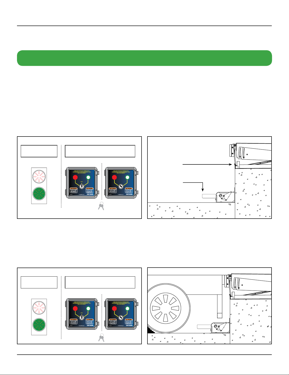
10.0 OPERATING INSTRUCTIONS - STRONGARM™ ML10 WITH TLC24 CONTROLS (AUTOMATIC & MANUAL)
10.1 PRIOR TO USE: EQUIPMENT IN HOME
POSITION
The restraint apparatus is in the home position and the dock leveler
lip is parked safely in the lip keepers.
OUTSIDE TRAFFIC
LIGHT STATUS
OUTSIDE TRAFFIC
LIGHT STATUS
INSIDE COMMUNICATION
LIGHTS & CONTROL STATION
STANDARD OPERATION PROCEDURES
INSIDE COMMUNICATION
LIGHTS & CONTROL STATION
AUTOMATIC MANUAL
The TLC24-M has interior and exterior LED light signals (red / green) that are manually controlled to communicate safety conditions to
both dock workers and truck drivers. The TLC24-A, when operating in automatic mode, detects the position of the interlocked restraint
or dock lip via a sensor, allowing the lights to automatically change according to the relevant safety conditions. It may also be operated
in manual mode if necessary.
10.2 TRAILER AT BAY
The truck reverses into position against the dock leveler bumpers.
The outside traffic light is GREEN and the control station light
is RED. Chock the wheels and release the air from the air ride
suspension system (if applicable).

19
STRONGARM™ ML10 VEHICLE RESTRAINT—OWNER’S MANUAL
ISSUE DATE: SEPTEMBER 29, 2014 REV.0 (PART # 038-538E)
10.3 ENGAGING RESTRAINT
Activate the ML10 by using the control rod to press down on
the engagement arm until the restraint arm is in the fully vertical
position, holding the ICC bar in place.
TLC24-A: The control station light will turn GREEN and the outside
traffic light will turn RED in auto mode.
TLC24-M: Turn the key switch to the 'Interlocked' position (green
LED light). The outside traffic light changes to RED while GREEN
light on the control station comes on.
NOTE: The truck / trailer is NOT restrained if the arm is not fully
vertical. Do not switch the TLC24-M to green until you have
confirmed the restraint arm is fully deployed and locked in.
TLC24-A TLC24-M
OUTSIDE TRAFFIC
LIGHT STATUS
INSIDE COMMUNICATION
LIGHTS & CONTROL STATION
PERFORM LOADING AND UNLOADING
10.4 RELEASING THE RESTRAINT ARM
After loading / unloading has been completed and the dock leveler
is safely parked, release the restraint arm by pulling up on it quickly
and firmly using the control rod. The arm will return to the parked
position.
TLC24-A: The control station light will turn RED and the outside
traffic light will turn GREEN in auto mode.
TLC24-M: turn the key switch to the 'No Traffic' (red LED light)
position. The outside traffic light changes to GREEN and the
control station light turns RED.
NOTE: If the ICC bar is applying pressure to the restraint arm, it
may be necessary to have the driver back up the vehicle before
releasing the arm.
TLC24-A TLC24-M
OUTSIDE TRAFFIC
LIGHT STATUS
INSIDE COMMUNICATION
LIGHTS & CONTROL STATION
OPPOSITE SIDE

20
STRONGARM™ ML10 VEHICLE RESTRAINT—OWNER’S MANUAL
ISSUE DATE: SEPTEMBER 29, 2014 REV.0 (PART # 038-538E)
OVERRIDE FEATURES
OUTSIDE TRAFFIC
LIGHT STATUS
INSIDE COMMUNICATION
LIGHTS & CONTROL STATION
LEVELER PARKED
IN HOME POSITION
Under these circumstances, a supervisor or designated authority
may operate the TLC24-A in manual override mode by using the
key switch to operate the lights manually.
10.5 MANUAL OVERRIDE MODE (TLC24-A)
Situations may arise that require the TLC24-A to be operated
manually. For example:
• ThetruckICCbarisbent,damaged,ormissing
• Theinterlocksensorisbrokenorotherwiseinoperable
REASON AND OPERATION OF KEYS
• Supervisorusage
• Automodeisstandard
• Keysrequiredtoswitchselectortoanyothermode/position
Table of contents
Other Blue Giant Jack manuals


 operating instructions")


