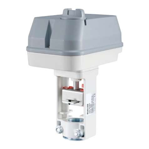
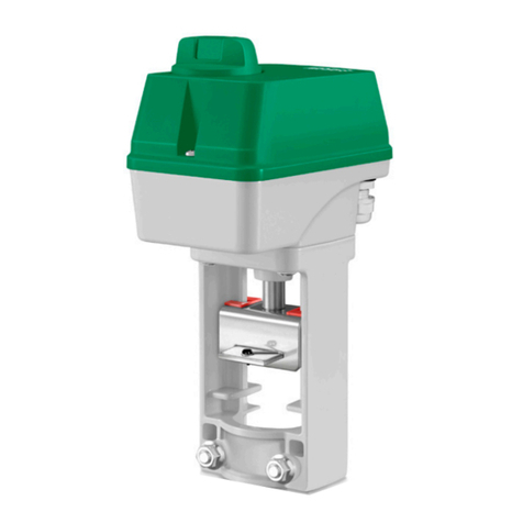
Regin RVAB4-24 User manual

EN INSTRUCTION
RVAB4/RVAB5
IN20011 REV. C, 2021-03-09
CCaauuttiioonn!! Rea an un erstan the instruction before using the pro uct.
CCaauuttiioonn!! Ensure that the installation complies with local safety
regulations.
WWaarrnniinngg!! Before installation or maintenance, the power supply must first
be isconnecte in or er to prevent potentially lethal electric shocks! In-
stallation or maintenance of this unit shoul only be carrie out by quali-
fie personnel. The manufacturer is not responsible for any eventual
amage or injury cause by ina equate skills uring installation, or through
removal of or eactivation of any security evices.
Technical Data
Ambient temperature -5…+50 °C
Storage temperature -30…+70 °C
Ambient humidity Max. 90 % RH (non-condensing)
Protection class IP54
Working angle 90°
Connection, actuator Square 9 mm hole with M5 screw
Mo els
Article Supply
voltage
Power
con-
sump-
tion
Control
signal
Torque Running
time,
actuator
Valve
RVAB4-24 24 V AC 3 VA Floating
or On/off
(3-wire)
≥ 4 Nm 45 s / 90° BV2/BV3
DN15…
DN25
RVAB4-24A 24 V AC 4 VA 0(2)…10
V DC or 0
(4)…20
mA
≥ 4 Nm 45 s / 90° BV2/BV3
DN15…
DN25
RVAB4-230 230 V ~ 5 VA Floating
or On/off
(3-wire)
≥ 4 Nm 45 s / 90° BV2/BV3
DN15…
DN25
RVAB5-24 24 V AC 3 VA Floating
or On/off
(3-wire)
≥ 5 Nm 50 s / 90° BV2/BV3
DN32…
DN50
RVAB5-24A 24 V AC 4 VA 0(2)…10
V DC or 0
(4)…20
mA
≥ 5 Nm 50 s / 90° BV2/BV3
DN32…
DN50
RVAB5-230 230 V ~ 5 VA Floating
or On/off
(3-wire)
≥ 5 Nm 50 s / 90° BV2/BV3
DN32…
DN50
Installation
The valve and actuator should never be mounted at an angle of more
than 90°.
90º
90º
min. 100 mm
Mounting the actuator on the valve
A justing the limit
1
2
3
4
A
To reach the limit adjuster (A):
1. Unscrew the screw that holds the lever
. Unscrew the screws that holds the cover of the actuator
3. Remove the lever
4. Remove the cover
RVAB4/RVAB5 1

Wiring
1 32
M
SW1 SW2
Figure 1 Floating / On/off (3-wire)
Power supply Rotate to
1-2 0°
2-3 90°
M
PCB
1 2 3(+) 4(+)
Figure 2 0…10 V DC
Terminal Colour Description
1 Red Supply voltage 24 V AC
2 Blue System neutral
3 Yellow Control signal 0(2)…10 V DC or 0(4)…20 mA
4 Green Signal feedback 0…10 V DC
Input control signal DA Input control signal RA Actuator stem
Increase Decrease To 90°
Decrease Increase To 0°
PCB settings
0 00
0 0 0
SW1
SW2
SW3
NC
NO
JP1
OFF ON
1 2 3 4
P1
1 2 3 4
LED1
Figure 3 PCB RVAB4
SW3
NC
NO
0 00
SW2
OFF ON
1 2 3 4
0 0 0
NO NC
SW1
JP1
1 2 3 4
LED1
Figure 4 PCB RVAB
Stu y status
After the power is switched on, set the JP1 switch as desired, see Table 1
JP1 switch setting.
1. Set switch 4 of JP1 to position ON.
. Press the SW1 button.
The power light (LED1) will start to flash and the actuator stem will
rotate to the end of the stroke. Then it will rotate back to the initial
position and the power light will stop flashing and be turned on to
indicate that study status is over. The actuator will keep the data in
memory even when the power is turned off.
3. Set switch 4 of JP1 back to position OFF to change to running status.
Running status
The actuator will return to fully closed position every time when the
power is on. It will first close the valve, and then the power light (LED1)
will be turned on to indicate that the actuator is ready for control signal.
Switching between stu y status an running status
To switch between study/running status, make sure that JP1 has been set
correctly, then press the SW1 button. There is no need to turn off the
power.
Table 1 JP1 switch setting
Status switch Control signal
0…10 V DC 2…10 V DC 0…20 mA 4…20 mA
Running status
DA
OFF ON
1 2 3 4
OFF ON
1 2 3 4
OFF ON
1 2 3 4
OFF ON
1 2 3 4
Running status
RA
OFF ON
1 2 3 4
OFF ON
1 2 3 4
OFF ON
1 2 3 4
OFF ON
1 2 3 4
Study status
DA
OFF ON
1 2 3 4
OFF ON
1 2 3 4
OFF ON
1 2 3 4
OFF ON
1 2 3 4
Study status
RA
OFF ON
1 2 3 4
OFF ON
1 2 3 4
OFF ON
1 2 3 4
OFF ON
1 2 3 4
DA = Direct action, RA = Reverse action
This product carries the CE-mark. More information is available at
www.regincontrols.com.
Documentation
All documentation can be downloaded from www.regincontrols.com.
Contact
AB Regin, Box 116, 4 8 Kållered, Sweden
Tel: +46 31 7 0 0 00, Fax: +46 31 7 0 0 50
www.regincontrols.com, [email protected]
RVAB4/RVAB5 2

SE INSTRUKTION
RVAB4/RVAB5
OObbsseerrvveerraa!! Läs och förstå instruktionen innan u använ er pro ukten.
OObbsseerrvveerraa!! Se till att installationen uppfyller lokala
säkerhetsbestämmelser.
VVaarrnniinngg!! Innan installation eller un erhåll måste matningsspänningen först
kopplas från för att un vika potentiellt ö liga elstötar! Installation eller
un erhåll av enna enhet ska en ast utföras av kvalificera personal. Till-
verkaren är inte ansvarig för eventuella ska or som orsakas av felaktig in-
stallation och/eller inaktivering eller borttagning av säkerhetsanor ningar.
Tekniska ata
Omgivningstemperatur -5…+50 °C
Lagringstemperatur -30…+70 °C
Omgivande luftfuktighet Max. 90 % RH, icke-kondenserande
Skyddsklass IP54
Arbetsvinkel 90°
Anslutning, ställdon 9 mm kvadratiskt hål med M5-skruv
Mo eller
Artikel Mat-
nings-
spän-
ning
Ström-
förbruk-
ning
Styrsig-
nal
Vridmo-
ment
Gångtid,
ställdon
Ventil
RVAB4-24 24 V AC 3 VA 3-punkt
eller on/
off (3
kablar)
≥ 4 Nm 45 s / 90° BV2/BV3
DN15…
DN25
RVAB4-24A 24 V AC 4 VA 0(2)…10
V DC el-
ler 0(4)…
20 mA
≥ 4 Nm 45 s / 90° BV2/BV3
DN15…
DN25
RVAB4-230 230 V ~ 5 VA 3-punkt
eller on/
off (3
kablar)
≥ 4 Nm 45 s / 90° BV2/BV3
DN15…
DN25
RVAB5-24 24 V AC 3 VA 3-punkt
eller on/
off (3
kablar)
≥ 5 Nm 50 s / 90° BV2/BV3
DN32…
DN50
Artikel Mat-
nings-
spän-
ning
Ström-
förbruk-
ning
Styrsig-
nal
Vridmo-
ment
Gångtid,
ställdon
Ventil
RVAB5-24A 24 V AC 4 VA 0(2)…10
V DC el-
ler 0(4)…
20 mA
≥ 5 Nm 50 s / 90° BV2/BV3
DN32…
DN50
RVAB5-230 230 V ~ 5 VA 3-punkt
eller on/
off (3
kablar)
≥ 5 Nm 50 s / 90° BV2/BV3
DN32…
DN50
Installation
Ventilen och ställdonet ska aldrig monteras i en vinkel som överskrider
90°.
90º
90º
min. 100 mm
Montering av ställ on på ventil
Justera begränsning
1
2
3
4
A
För att komma åt begränsaren (A):
1. Skruva loss skruven som håller vredet
. Skruva loss skruven som håller ställdonets kåpa
3. Ta av vredet
4. Ta av kåpan
RVAB4/RVAB5 3

Inkoppling
1 32
M
SW1 SW2
Figur 1 3-punkt / On/off (3 kablar)
Strömförsörjning Rotera till
1-2 0°
2-3 90°
M
PCB
1 2 3(+) 4(+)
Figur 2 0…10 V DC
Plint Färg Beskrivning
1 Röd Matningsspänning 24 V AC
2 Blå Systemnoll
3 Gul Styrsignal 0(2)…10 V DC eller 0(4)…20 mA
4 Grön Återkopplingssignal 0…10 V DC
Ingång styrsignal DA Ingång styrsignal RA Ställdonsaxel
Öka Minska Till 90°
Minska Öka Till 0°
PCB-inställningar
0 00
0 0 0
SW1
SW2
SW3
NC
NO
JP1
OFF ON
1 2 3 4
P1
1 2 3 4
LED1
Figur 3 PCB RVAB4
SW3
NC
NO
0 00
SW2
OFF ON
1 2 3 4
0 0 0
NO NC
SW1
JP1
1 2 3 4
LED1
Figur 4 PCB RVAB
Än lägestest
När strömmen är påslagen, ställ JP1-brytarna enl. önskemål, se Tabell 1
JP1 brytarinställningar.
1. Sätt JP1 brytare 4 till läge ON.
. Tryck på SW1-knappen.
Strömindikatorn (LED1) börjar att blinka och ställdonsaxeln roterar
till ändläget. Därefter roterar den tillbaka till startpositionen och
strömindikatorn slutar att blinka och slås på för att indikera att
ändlägestestet är klart. Ställdonet sparar datat i minnet även när
strömmen är avstängd.
3. Ställ JP1 brytare 4 till läge OFF för att ändra till normalt körläge.
Normalt körläge
Ställdonet återgår till helt stängt läge varje gång strömmen slås på. Först
stänger det ventilen, därefter slås strömindikatorn (LED1) på för att
indikera att ställdonet är redo för styrsignal.
Byte mellan än lägestest och normalt körläge
För att byta mellan ändlägestest och normalt körläge, säkerställ att JP1 är
korrekt inställd och tryck därefter på SW1-knappen. Strömmen behöver
inte slås av.
Tabell 1 JP1 brytarinställningar
Statusbrytare Styrsignal
0…10 V DC 2…10 V DC 0…20 mA 4…20 mA
Normalt körlä-
ge DA
OFF ON
1 2 3 4
OFF ON
1 2 3 4
OFF ON
1 2 3 4
OFF ON
1 2 3 4
Normalt körlä-
ge RA
OFF ON
1 2 3 4
OFF ON
1 2 3 4
OFF ON
1 2 3 4
OFF ON
1 2 3 4
Ändlägestest
DA
OFF ON
1 2 3 4
OFF ON
1 2 3 4
OFF ON
1 2 3 4
OFF ON
1 2 3 4
Ändlägestest
RA
OFF ON
1 2 3 4
OFF ON
1 2 3 4
OFF ON
1 2 3 4
OFF ON
1 2 3 4
DA = Direkt verkan, RA = Omvänd verkan
Produkten är CE-märkt. Mer information finns på www.regincontrols.
com.
Dokumentation
All dokumentation kan laddas ner från www.regincontrols.com.
Kontakt
AB Regin, Box 116, 4 8 Kållered, Sverige
Tel: +46 31 7 0 0 00, Fax: +46 31 7 0 0 50
www.regincontrols.com, [email protected]
RVAB4/RVAB5 4

DE INSTALLATIONSANLEITUNG
RVAB4/RVAB5
VVoorrssiicchhtt Lesen Sie iese Montageanleitung vor Einsatz es Pro uktes
urch.
VVoorrssiicchhtt Vergewissern Sie sich, ass ie Installation ie lokalen Sicher-
heitsanfor erungen erfüllt.
WWaarrnnuunngg Vor er Installation o er er Wartung muss ie Stromversor-
gung getrennt wer en, um tö liche Stromschläge zu vermei en. Montage
un Wartung ieses Geräts ürfen nur von Fachkräften urchgeführt wer-
en. Der Hersteller haftet nicht für Schä en, ie urch mangeln e Fach-
kenntnisse bei er Installation un /o er Sicherheitsvorkehrungen, ie
entfernt o er manipuliert wur en, verursacht wer en.
Technische Daten
Umgebungstemperatur -5…+50°C
Lagerungstemperatur -30...+70°C
Umgebungsfeuchte Max. 90 % rel. F., (nicht kondensierend)
Schutzart IP54
Arbeitsbereich 90°
Anschluss Drehantrieb Quadratisches 9mm Loch mit M5 Schraube
Mo elle
Artikel Versor-
gungs-
span-
nung
Leis-
tungs-
aufnah-
me
Regel-
signal
Drehmo-
ment
Laufzeit,
Stellan-
trieb
Kugel-
hahn
RVAB4-24 24 V AC 3 VA Stetig
oder Auf/
Zu (3-
Draht)
≥ 4 Nm 45 s / 90
°
BV2/BV3
DN15...
DN25
RVAB4-24A 24 V AC 4 VA 0(2)…10
V DC
oder 0(4)
…20 mA
≥ 4 Nm 45 s / 90
°
BV2/BV3
DN15...
DN25
RVAB4-230 230 V ~ 5 VA Stetig
oder Auf/
Zu (3-
Draht)
≥ 4 Nm 45 s / 90
°
BV2/BV3
DN15...
DN25
RVAB5-24 24 V AC 3 VA Stetig
oder Auf/
Zu (3-
Draht)
≥ 5 Nm 50 s / 90
°
BV2/BV3
DN32...
DN50
Artikel Versor-
gungs-
span-
nung
Leis-
tungs-
aufnah-
me
Regel-
signal
Drehmo-
ment
Laufzeit,
Stellan-
trieb
Kugel-
hahn
RVAB5-24A 24 V AC 4 VA 0(2)…10
V DC
oder 0(4)
…20 mA
≥ 5 Nm 50 s / 90
°
BV2/BV3
DN32...
DN50
RVAB5-230 230 V ~ 5 VA Stetig
oder Auf/
Zu (3-
Draht)
≥ 5 Nm 50 s / 90
°
BV2/BV3
DN32...
DN50
Installation
Der Kugelhahn und der Drehmotor sollten niemals mit einem seitlichen
Neigungswinkel von mehr als 90° installiert werden.
90º
90º
min. 100 mm
Installation es Drehantriebs auf em Kugelhahn
Begrenzung einstellen
1
2
3
4
A
Um den Begrenzer (A) zu erreichen:
1. Lösen Sie die Schraube, die den Hebel festhält
. Lösen Sie die Schraube, die den Deckel festhält
3. Entfernen Sie den Hebel
4. Entfernen Sie den Deckel
RVAB4/RVAB5 5

Ver rahtung
1 32
M
SW1 SW2
Bild 1 Stetig oder Auf/Zu (3-Draht)
Stromversorgung Drehung nach
1-2 0°
2-3 90°
M
PCB
1 2 3(+) 4(+)
Bild 2 0…10 V DC
Klemme Farbe Beschreibung
1 Rot Versorgungsspannung 24 V AC
2 Blau Masse
3 Gelb Regelsignal 0(2)…10 V DC oder 0(4)…20 mA
4 Grün Rückführsignal 0…10 V DC
Eingangsregelsignal
DA
Eingangsregelsignal
RA
Drehantrieb Spindel
ERHÖHEN SENKEN auf 90°
SENKEN ERHÖHEN Auf 0°
PCB Einstellung
0 00
0 0 0
SW1
SW2
SW3
NC
NO
JP1
OFF ON
1 2 3 4
P1
1 2 3 4
LED1
Bild 3 PCB RVAB4
SW3
NC
NO
0 00
SW2
OFF ON
1 2 3 4
0 0 0
NO NC
SW1
JP1
1 2 3 4
LED1
Bild 4 PCB RVAB
Lernphase
Nachdem die Stromversorgung abgeschaltet wurde, setzen Sie die
Schalter von JP1 in die gewünschte Position, sieheTabelle 1
Schaltereinstellungen JP1.
1. Setzen Sie Schalter 4 von JP1 auf die Position ON.
. Drücken Sie den SW1-Knopf.
Sie Stromversorgungsanzeige (LED1) beginnt zu blinken und die
Spindel vom Dremotor dreht sich bis zum Ende. Danach dreht sie
zurück in die Anfangsposition und die LED für die
Stromversorgungsanzeige hört auf zu blinken und leuchtet
durchgängig, um anzuzeigen, dass die Lernphase vorüber ist. Der
Drehmotor behält die Positionen gespeichert, auch wenn die
Stromzufuhr unterbrochen ist.
3. Setzen Sie Schalter 4 von JP1 zurück auf die Position OFF, um in
den Betriebsmodus zu gelangen.
Betriebsmo us
Der Drehmotor fährt in die "komplett geschlossen" Position, wenn die
Stromversorgung eingeschaltet wird. Nachdem der Kugelhahn
geschlossen ist leuchtet die Stromversorgungsanzeige (LED1) auf, um
anzuzeigen, dass der Drehmotor bereit für ein Regelsignal ist.
Wechseln zwischen Lernphase un Betriebsmo us
Um zwischen Lernphase und Betriebsmodus zu wechseln stellen Sie
sicher, dass die Schalter von JP1 richtig eingestellt sind und drücken Sie
dann den SW1 Knopf. Die Stromversorgung braucht nicht abgeschaltet
zu werden.
Tabelle 1 Schaltereinstellungen JP1
Statusschal-
ter
Regelsignal
0…10 V DC 2...10 V DC 0...20 mA 4...20 mA
Betriebsmo-
dus DA
OFF ON
1 2 3 4
OFF ON
1 2 3 4
OFF ON
1 2 3 4
OFF ON
1 2 3 4
Betriebsmo-
dus RA
OFF ON
1 2 3 4
OFF ON
1 2 3 4
OFF ON
1 2 3 4
OFF ON
1 2 3 4
Lernphase DA
OFF ON
1 2 3 4
OFF ON
1 2 3 4
OFF ON
1 2 3 4
OFF ON
1 2 3 4
Lernphase RA
OFF ON
1 2 3 4
OFF ON
1 2 3 4
OFF ON
1 2 3 4
OFF ON
1 2 3 4
DA = Direkte Wirkung, RA = Reversierte Wirkung
Dieses Produkt trägt das CE-Zeichen. Mehr Information können Sie auf
www.regincontrols.de finden.
Dokumentation
Alle Dokumente können auf www.regincontrols.de runtergeladen
werden.
Kontakt
Regin Controls Deutschland GmbH, Haynauer Str. 49, 1 49 Berlin,
Deutschland,
Tel: +49 30 77 99 4-0, Fax: +49 30 77 99 4-13,
www.regincontrols.de, [email protected]
RVAB4/RVAB5 6

FR INSTRUCTION
RVAB4/RVAB5
AAtttteennttiioonn !! Veuillez lire attentivement les instructions avant ’utiliser le
pro uit.
AAtttteennttiioonn !! Assurez-vous que l'installation est conforme aux normes e
sécurité locales.
AAvveerrttiisssseemmeenntt !! Avant e procé er à l'installation ou à la maintenance
e l'appareil, il convient e couper l'alimentation afin 'éviter tout risque
e choc électrique. Les opérations 'installation et e maintenance oi-
vent être effectuées par un professionnel qualifié. Le fabricant ne pourra
être tenu responsable 'éventuels ommages ou blessures causés par une
installation éfectueuse u pro uit, ou par la ésactivation es ispositifs
e sécurité.
Caractéristiques techniques
Température ambiante -5…+50 °C
Température de
stockage
-30…+70 °C
Humidité ambiante Max. 90 % HR (sans condensation)
Indice de protection IP54
Angle de travail 90°
Raccordement,
actionneur
Trou carré de 9 mm avec vis M5
Mo èles
Article Tension
d’ali-
menta-
tion
Puissan-
ce
consom-
mée
Signal
de
com-
mande
Couple Temps
de
course,
moteur
Vanne
RVAB4-24 24 VCA 3 VA Flottant
ou tout
ou rien (3
fils)
≥ 4 Nm 45 s. /
90°
BV2/BV3
DN15…
DN25
RVAB4-24A 24 VCA 4 VA 0(2)…
10 VCC
ou 0(4)…
20 mA
≥ 4 Nm 45 s. /
90°
BV2/BV3
DN15…
DN25
RVAB4-230 230 V ~ 5 VA Flottant
ou tout
ou rien (3
fils)
≥ 4 Nm 45 s. /
90°
BV2/BV3
DN15…
DN25
Article Tension
d’ali-
menta-
tion
Puissan-
ce
consom-
mée
Signal
de
com-
mande
Couple Temps
de
course,
moteur
Vanne
RVAB5-24 24 VCA 3 VA Flottant
ou tout
ou rien (3
fils)
≥ 5 Nm 50 s. /
90°
BV2/BV3
DN32…
DN50
RVAB5-24A 24 VCA 4 VA 0(2)…
10 VCC
ou 0(4)…
20 mA
≥ 5 Nm 50 s. /
90°
BV2/BV3
DN32…
DN50
RVAB5-230 230 V ~ 5 VA Flottant
ou tout
ou rien (3
fils)
≥ 5 Nm 50 s. /
90°
BV2/BV3
DN32…
DN50
Installation
La vanne et l'actionneur ne doivent jamais être installés avec un angle de
plus de 90°.
90º
90º
min. 100 mm
Montage e l’actionneur sur la vanne
Réglage e la limite
1
2
3
4
A
Pour atteindre le réglage limite (A) :
1. Desserrer la vis de maintien du levier
. Desserrer les vis du capot de l’actionneur
3. Retirer le levier
4. Retirer le capot
RVAB4/RVAB5 7

Raccor ement
1 32
M
SW1 SW2
Fig. 1 Flottant / tout ou rien (3 fils)
Alimentation électrique Tourner à
1-2 0°
2-3 90°
M
PCB
1 2 3(+) 4(+)
Fig. 2 0 à 10 VCC
Entrée
physique
Couleur Description
1 Rouge Tension d’alimentation 24 VCA
2 Bleu Neutre
3 Jaune Signal de commande 0(2)…10 VCC ou 0(4)…
20 mA
4 Vert Signal de recopie 0…10 VCC
Signal de commande
d’entrée DA
Signal de commande
d’entrée RA
Tige d’actionnement
Augmenter Diminuer À 90°
Diminuer Augmenter À 0°
Réglages PCB
0 00
0 0 0
SW1
SW2
SW3
NC
NO
JP1
OFF ON
1 2 3 4
P1
1 2 3 4
LED1
Fig. 3 PCB RVAB4
SW3
NC
NO
0 00
SW2
OFF ON
1 2 3 4
0 0 0
NO NC
SW1
JP1
1 2 3 4
LED1
Fig. 4 PCB RVAB
État e l’initialisation
À la mise sous tension, régler l’interrupteur JP1 comme souhaité, voir
Tableau 1 Réglage de l’interrupteur JP1.
1. Régler l’interrupteur 4 du JP1 sur la position ON.
. Appuyer sur le bouton SW1.
Le témoin d’alimentation (LED1) commence à clignoter et la tige
d’actionnement tourne jusqu’en fin de course. Ensuite, elle retourne
à sa position initiale et le témoin lumineux s’arrête de clignoter et
reste allumé pour indiquer que l'initialisation est terminée.
L’actionneur conserve les données en mémoire même en cas de mise
hors tension.
3. Remettre l’interrupteur 4 du JP1 à la position OFF pour modifier
l’état de fonctionnement.
État e fonctionnement
L’actionneur retourne en position entièrement fermée à chaque mise
sous tension. Il ferme d’abord la vanne, puis le témoin lumineux (LED1)
s’allume pour indiquer que l’actionneur est opérationnel.
Commutation entre l’initialisation et l’état e fonctionnement
Pour commuter entre l’initialisation et l’état de fonctionnement,
s’assurer que JP1 a été réglé correctement, puis appuyer sur le bouton
SW1. Il n’est pas nécessaire de couper le courant.
Tableau 1 Réglage de l’interrupteur JP1
Interrupteur
d’état
Signal de commande
0 à 10 VCC 2 à 10 VCC 0 à 20 mA 4 à 20 mA
État de fonc-
tionnement DA
OFF ON
1 2 3 4
OFF ON
1 2 3 4
OFF ON
1 2 3 4
OFF ON
1 2 3 4
État de fonc-
tionnement RA
OFF ON
1 2 3 4
OFF ON
1 2 3 4
OFF ON
1 2 3 4
OFF ON
1 2 3 4
Initialisation
DA
OFF ON
1 2 3 4
OFF ON
1 2 3 4
OFF ON
1 2 3 4
OFF ON
1 2 3 4
Initialisation
RA
OFF ON
1 2 3 4
OFF ON
1 2 3 4
OFF ON
1 2 3 4
OFF ON
1 2 3 4
DA = action directe, RA = action inverse
Ce produit porte le marquage CE. Pour plus d'information, veuillez
consulter le site web www.regincontrols.com.
Documentation
Toute la documentation est disponible sur notre site www.regin.fr.
Contact
Regin France, 3 Rue Delizy, 93694 Pantin
Tél. : +33 (0) 1 41 83 0 0 , Fax : +33 (0) 1 57 14 95 91
www.regincontrols.fr, [email protected]
RVAB4/RVAB5 8
This manual suits for next models
5
Table of contents
Languages:
Other Regin Controllers manuals

Regin
Regin RVAZ4-24 User manual

Regin
Regin RVAN10-230 User manual

Regin
Regin AQUA230T User manual

Regin
Regin RDAS7S Series User manual

Regin
Regin ALC230A User manual

Regin
Regin RVAZ4-24A User manual

Regin
Regin TTC25 User manual

Regin
Regin TT-S4/D User manual

Regin
Regin RVAN5-24A User manual

Regin
Regin RVAPC-230 User manual

Regin
Regin Corrigo U10 Series User manual

Regin
Regin TT-S4/D User manual

Regin
Regin EXOCLEVER EC-PU4-2 User manual

Regin
Regin ED-RUD User manual

Regin
Regin ED-RU-FO User manual

Regin
Regin RVAZ2-24 User manual

Regin
Regin Regio Midi User manual

Regin
Regin PULSER-M User manual

Regin
Regin RVAR5-230 User manual

Regin
Regin RVAZ4L1-24A User manual