Installation
6
Blue Seal Evolution Series Gas Pasta Cooker G47 © Moffat Ltd, January 007
Revision 1/
Gas Connection
NOTE: ALL GAS FITTING MUST ONLY BE CARRIED OUT BY A QUALIFIED SERVICE PERSON.
1. Blue Seal Pasta Cookers do not require an electrical connection, they function totally on the gas
supply only.
. It is essential that the gas supply is correct for the appliance to be installed and that adequate
supply pressure and volume are available. The following checks should therefore be made before
installation:-
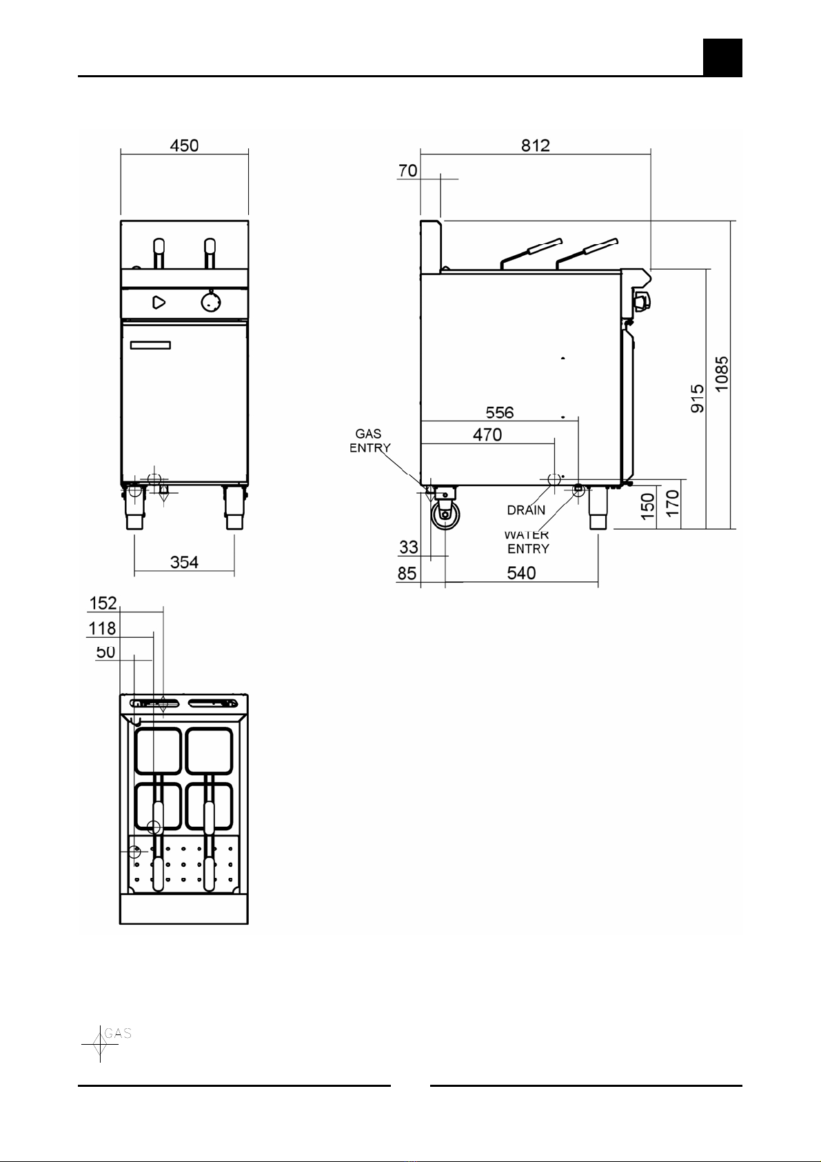
a. The Gas Type the appliance has been supplied for is shown on
coloured stickers located above the gas entry point and next to
the rating plate. Check that this is correct for the gas supply
the appliance is being installed for. The gas conversion
procedure is detailed in this manual.
b. Supply Pressure required for this appliance is shown in the
“Specifications” section of this manual. Check the gas supply to
ensure that adequate supply pressure exists.
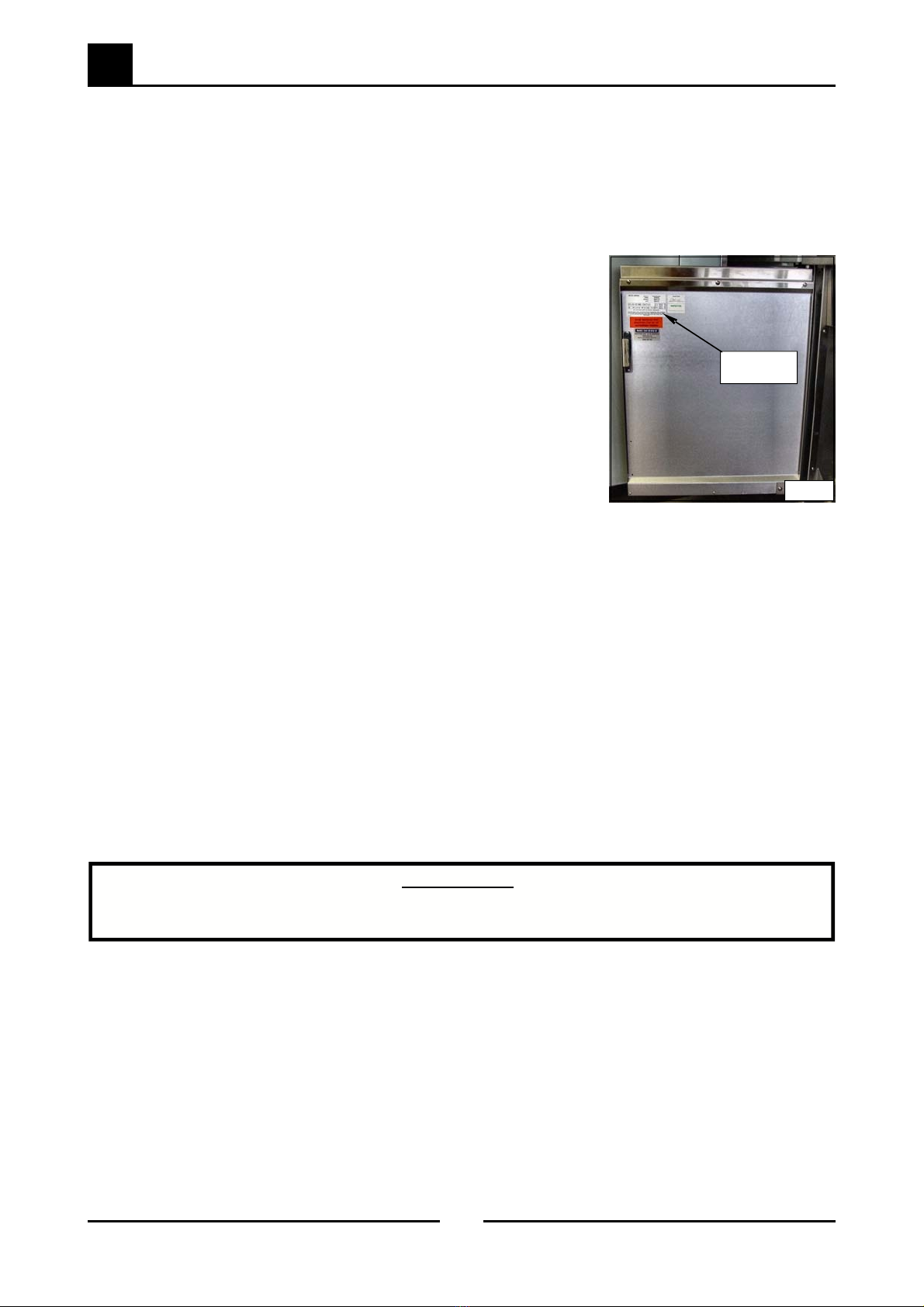
c. Input Rate of this appliance is also stated on the Rating Plate
fitted to the inside of the access door and in the
“Specifications” section of this manual. The input rate should
be checked against the available gas supply line capacity.
Particular note should be taken if the appliance is being
added to an existing installation.
NOTE: It is important that adequately sized piping runs directly to the connection joint on the
appliance, with as few tees and elbows as possible to give maximum supply volume.
3. A suitable joining compound which resists the breakdown action of LPG must be used on every gas
line connection, unless compression fittings are used.
The connection to the appliance is 3/4” BSP male.
NOTE: A Manual Isolation Valve must be fitted to the individual appliance supply line.
4. Correctly locate the appliance into its final operating position and using a spirit level, adjust the legs
so that the unit is level and at the correct height.
5. Connect the gas supply to the appliance.
6. Check gas operating pressure to as shown in the “Specifications” section. If the pressure is
incorrect, adjust the pressure by adjusting the regulator screw of the gas control valve as shown in
the ‘Gas Conversion and Specifications’ section.
7. Check all gas connections for leakages using soapy water or other gas detecting equipment.
NOTE: The operating pressure is to be measured at the Burner Operating Pressure test point
on the gas control valve, this is to be carried out with the burner operating at the 'High
Flame' setting. The operating pressure is ex-factory set, through the appliance
regulator and not to be adjusted, apart from when carrying out gas conversion, if
required. Refer to the ‘Gas Conversion and Specification’ Section for further details .
Rating Plate
Location
Fig .
WARNING:
DO NOT USE A NAKED FLAME TO CHECK FOR GAS LEAKAGES .