Blue Sky Network D411 User manual

D411
Installation Guide
Version 1.0
Part# 100505

D411 Installation Guide Notice
NOTICE
This guide is published and copyrighted by Blue Sky Network (BSN). All information and specifications in this
document are subject to change without notice. Nothing in this document is intended to create additional or
separate warranties or guarantees.
© 2014 Blue Sky Network, All Right Reserved.
Blue Sky Network, 5333 Mission Center Rd. Suite 220, San Diego, CA 92108
Phone: +1 858 551 3894 | Fax: +1 858 225 0794
E: support@blueskynetwork.com | W: www.blueskynetwork.com
100505 Page 2of 19

D411 Installation Guide Table of Contents
TABLE OF CONTENTS
Notice ..............................................................................................................................2
Table of Contents ............................................................................................................3
Introduction......................................................................................................................5
D411.................................................................................................................................................................5
SkyRouter ........................................................................................................................................................6
Technical Specifications ..................................................................................................................................7
Features ...........................................................................................................................................................7
Connectors.......................................................................................................................................................7
Getting Started ................................................................................................................8
Activate ............................................................................................................................................................8
Installation .......................................................................................................................9
Mounting ..........................................................................................................................................................9
Installing Cables...............................................................................................................................................9
Power Cable - 100504 ...................................................................................................................................10
Cigarette Lighter Adapter - 100297................................................................................................................11
Fixed Installation (vehicle) ..............................................................................................................................11
Power Cable Wiring Diagram.........................................................................................................................12
Connecting the Antenna – AN100107 ...........................................................................................................13
Antenna Positioning .......................................................................................................................................13
Antenna specifications ...................................................................................................................................14
Antenna Cable Specifications ........................................................................................................................14
Quick Position Switch.....................................................................................................................................15
Configure....................................................................................................................... 16
Parameters.....................................................................................................................................................16
SkyRouter Parameter Update Screen .......................................................................................................16
D411 Parameter Explanation .....................................................................................................................16
Appendix .......................................................................................................................17
100505 Page 3of 19

D411 Installation Guide Table of Contents
Appendix A – Revision History.......................................................................................................................17
Appendix B – Power Up Test.........................................................................................................................18
Support..........................................................................................................................19
100505 Page 4of 19

D411 Installation Guide Introduction
INTRODUCTION
This guide is applicable to the following components:
•100505 - D411 Iridium/GPS Vehicle Tracking Device
•AN-100107 - Iridium/GPS Antenna
•100504 - D411 16-pin Power Cable and QPos Assembly
•100297 - Cigarette Lighter Adapter (optional)
•CA-130210 - Coaxial cable SMA-SMA
NOTE: Information, drawings and wiring diagrams contained in this manual are intended as a
reference for engineering planning only. Drawings and wiring diagrams contained herein do not
represent any specific installation. It is the installer’s responsibility to create installation drawings
specific to the mobile asset.
D411
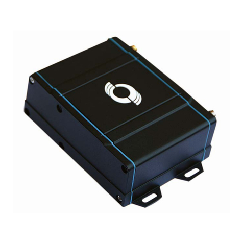
The Blue Sky Network’s D411 is an Iridium and GPS mobile tracking platform with 6-28 VDC input.
All data services are managed by the customer through our web-based SkyRouter portal. SkyRouter offers
global asset tracking, account management features, such as user authorization, asset settings, messaging
and billing information. For more information on SkyRouter please visit: http://www.blueskynetwork.com
Blue Sky Network D411
100505 Page 5of 19

D411 Installation Guide Introduction
SKYROUTER
The SkyRouter portal ties together Blue Sky Network data solutions in an integrated and user-friendly way.
By accessing the SkyRouter Web-site users can do the following:
Advanced device tracking on a global, layered map including satellite imagery and standard
street maps.
Event notification for emergency, take-off, landing, inactive unit, speeding, moving and not-
moving and more.
Playback past trips and view detailed reports.
2-way email messaging to and from devices in the field.
Update and request the current state of parameters on devices in the field.
Manage alert settings.
Management of a device fleet, including assignment of units to groups and creation of additional
user accounts.
Manage naming of the units and many other visual characteristics.
100505 Page 6of 19

D411 Installation Guide Introduction
TECHNICAL SPECIFICATIONS
Dimensions
103.0mm x 61.2mm x 194.6mm
Weight
1.4lb or 0.63Kg
Power Requirements
6-28 VDC (maximum 3W)
Current Draw
0.091A @ 28VDC
Operating Temperature Range
-20 degrees C to + 70 degrees C
Iridium Frequency
1616.0 MHz – 1626.5 MHz
GPS Frequency
L-Band (1575.42 MHz)
Antenna
Iridium and GPS combined
FEATURES
Iridium satellite link: The D411 communicates to SkyRouter using the Iridium network of 66 Low Earth
Orbit (LEO) satellites.
GPS: The D411 has an integrated GPS receiver – Position reporting interval can be
changed in SkyRouter.
Asset Tracking: Directly from our web-portal, SkyRouter (www.blueskynetwork.com), users can view
the location of assets.
CONNECTORS
The graphic below shows the D411 back panel and describes its connectors:
A. Iridium antenna connector (SMA Female)
B. GPS antenna connector (SMA Female)
C. 16-pin power connector (Male)
100505 Page 7of 19

D411 Installation Guide Getting Started
GETTING STARTED
ACTIVATE
Your D411 device must be activated prior to use.
By default all Blue Sky Network tracking devices are shipped to customers in an un-activated state. All
activation requests must be submitted by the Blue Sky Network SkyRouter Administrator on file.
An activation request can be submitted through our website, the link is shown below. You should receive an
immediate email confirmation that your request has been submitted and another email once the requested
services have been activated. Please make sure your contact details are accurate, this is how we contact
you if there are any problems processing your request.
http://www.blueskynetwork.com/
100505 Page 8of 19

D411 Installation Guide Installation
INSTALLATION
MOUNTING
Choose a convenient mounting location – possible locations include: the trunk, on the firewall for covert
installations or in the interior of a vehicle. Avoid locations that might expose the device to excessive heat or
moisture.
•Hold the D411 in place and mark the location for mounting screw holes.
•Using the markings as a guide, drill mounting holes in those positions.
•Align the D411 in the drilled holes and secure it with mounting screws.
The mounting holes are designed for number 10 screws. After the holes are drilled, loosely install the four
mounting screws, place the unit over the screws and slide to either the left of right to allow the screws to
engage the notches in the flange. Tighten all four screws.
INSTALLING CABLES
During installation, the following precautions will help ensure proper operation of the D411:
•Remove power from the D411 until all other connections have made and verified.
•Do not create loops, sharp bends or crimps in the cables
•All cables should be mounted in such a way as to reduce stress or wear caused by vibration generated
by moving vehicles
•Use proper terminations on all power cables to prevent electrical shorts.
100505 Page 9of 19

D411 Installation Guide Installation
POWER CABLE - 100504
BSN 100504 D411 Power Cable is supplied with the D411. This power cable includes a 16-pin power
connector (to D411), a 2-pin Molex power connector (to power source), and a Quick Position remote switch.
The D411 has an input voltage of 6-28 VDC.
•Use of the device outside of the specified voltage range may result in damage to the device and/or
undesirable results.
•Blue Sky Network is not liable for damage to the D411 caused by an improper installation.
•The D411 is designed to operate on 6-28 VDC. The user is responsible for ensuring the voltage
supplied to the D411 remains in this voltage range to include transient voltage spikes and load dump
voltages. Failure to comply with this warning may result in damage to the D411.
•The 16-pin Power Connector connects directly to the D411 Power Port. The connector must be
securely connected and screwed down using the black plastic bezel.
The D411 Power Cable:
A. QuickPosition Switch
B. 2-pin Molex connector (Male)
C. 16-pin Power Connector (Female)
100505 Page 10 of 19


D411 Installation Guide Installation
POWER CABLE WIRING DIAGRAM
100505 Page 12 of 19

D411 Installation Guide Installation
CONNECTING THE ANTENNA – AN100107
The user must supply the BSN AN-100107 Iridium/GPS antenna (available for purchase from
sales@blueskynetwork.com.) The proper antenna must have:
•A nominal impedance of 50 Ohms
•A VSWR less than 2.0:1
•A gain 0 – 3 dB for optimum performance
•An SMA female for Iridium and SMA female connector for GPS
•An active GPS antenna (3.3VDC)
The GPS antenna connector is labelled ‘GPS’. Make certain that the GPS cable is connected to the GPS
output on the antenna to the GPS input on the D411, and that the Iridium cable is connected to the
Iridium connector on both the D411 and the antenna. Failure to do so can damage both the antenna
and D411.
The antenna must be placed in an area where it can have an unrestricted direct view of the sky for better
GPS/Iridium reception. It is recommended that the antenna cables are connected prior to
supplying power to the D411 unit.
ANTENNA POSITIONING
For optimum performance, the antenna must be installed on the upper surface of the vehicle and with an
unrestricted view of the sky down to eight degrees above the horizon (similar to a GPS antenna).
Transmission from the antenna may be affected by, and can affect the operation of other systems and it
is the installer’s responsibility to evaluate the location for any possible RF interference. In particular, the
Iridium frequency is near the allocated GPS and Inmarsat band. The antenna should be at least 39 inches
(1 meter) from any L-band antennas, particularly GPS, TCAS and Transponder antennas.
Observe all appropriate sections of AC 43.13-1B and AC 43.13-2A.
Strict maximum attenuation requirements for the coax cable and connectors that link the Antenna to the
D411 Unit must be observed. The signal loss budget, including the antenna cable and all connector, from
the antenna to the D411 Unit is < 2dB @1626MHz.
100505 Page 13 of 19

D411 Installation Guide Installation
ANTENNA SPECIFICATIONS
BSN AN-100107 - High performance GPS antenna with high-gain, low noise amplifier with an integrated
passive Iridium antenna:
•Mounting screw with slot for easy through hole stud installations
•Low profile, waterproof
•Operating frequency: 1616.0-1626.5 MHz RX/TX (Iridium), 1575MHz (GPS)
•Operating temperature range: -40°C to +80°C / -40°F to +176°F
•Protection Class: IP66
•VSWR <=1.8
•GPS Gain: 2 dBic
•Dimensions: 124mm (L) x 80mm (W) x 21mm (H)
•Polarization: RHCP
It is ideal for those applications that require durability, compact size, covert installation and ruggedized
construction. DO NOT PAINT THE ANTENNA
BSN AN-100107 Antenna
ANTENNA CABLE SPECIFICATIONS
BSN CXTK24K-15 – 15ft Low loss, flexible SMA Male to SMA Male coaxial cable.
•Jacket color: Black
•Jacket material: Non-halogenated PE
•Impedance: 50 Ohms
•Operating temperature: -40 °C to +85 °C
/ -40 °F to +185 °F
•Minimum bend radius: 19.10 mm
•Attenuation (15ft @ 1575-1626.5MHz):
1.7-1.8 dB
100505 Page 14 of 19

D411 Installation Guide Installation
QUICK POSITION SWITCH
The D411 comes with an LED wired remote Quick Position switch. The Quick Position switch is already
wired into the supplied D411 harness.
When the Quick Position mode is enabled this causes the D411 to transmit a series of QPOS (Quick
Position) events to SkyRouter. The number of messages and the time between messages can be
configured from SkyRouter (see Configure section of this guide for further information.)
When the Quick Position switch is in the ON position the LED inside the switch is ON. When the Quick
Position switch is in the OFF position the LED inside the switch will be OFF.
D411 Quick Position cable and switch
100505 Page 15 of 19

D411 Installation Guide Configure
CONFIGURE
PARAMETERS
Before using your D411 it is recommended that you take time to check and update the parameters on the
device to prevent unexpected data usage. By default Blue Sky Network configures the D411 at the
factory default setting of 120 second reporting (reports once every 2 minutes.)
The D411 system parameters are all managed using the SkyRouter system. Administrators of
SkyRouter can customize the parameters from the SkyRouter interface and update devices remotely
(device must be powered on and have sufficient signals to receive the update.) Please consult your
SkyRouter user manual for more specific information about sending parameter updates.
Adjusting the parameters on your device will change the behavior of your device. Some parameters
control the frequency at which normal position reports are sent, and other will generate events that will be
sent in addition to your normal position reports.
SKYROUTER PARAMETER UPDATE SCREEN
The following images show the available D411 parameters as seen in the SkyRouter user interface, these
are the default settings:
D411 PARAMETER EXPLANATION
Normal Position Reports
GPS Position Reporting
Enabled
This option will enable or disable normal position reports to be generated
based upon a timer.
Time Based Interval
Normal position reports will be generated at this interval.
Event Reporting
Quick Position Events
Reporting Interval (sec): Reporting interval when Quick Position is activated.
Count Number of Quick Position messages to be sent.
100505 Page 16 of 19

D411 Installation Guide Appendix
APPENDIX
APPENDIX A – REVISION HISTORY
Date Revision By Description
2014-11-17 1.0 MP Initial version D411 Installation Guide
100505 Page 17 of 19
2017-03-21 1.1 AN Updated the address

D411 Installation Guide Appendix
APPENDIX B – POWER UP TEST
After D411 is installed and Power and Antenna connections are properly secured, a Power-Up Test
(PUT) is strongly recommended. BEFORE YOU START; please make sure the unit has been registered
in your SkyRouter user account and is activated.
Power-Up Test:
1. Ensure that the Power Connector is securely connected to the D411
2. Ensure that the GPS and Iridium antenna connectors (at both the D411 and Antenna end) are
securely connected to the correct terminals.
3. Supply power to the D411 unit.
4. Wait 5 minutes.
a. The D411 should acquire GPS and Iridium signals and begin reporting within 5 minutes
assuming the antenna a clear view of the sky.
5. Confirm that the D411 is sending reports
a. Log into SkyRouter using the login information provided by your account administrator
and verify that the D411 sending Position Report Data to SkyRouter.
If you are having problems with any of the steps above; make sure the power connection is reliable,
antenna cables are securely connected and the Antenna has a clear view of the sky.
100505 Page 18 of 19

D411 Installation Guide Support
SUPPORT
Please do not hesitate to contact us either via email, phone or, for self-help, see
http://www.blueskynetwork.com/Support/Support.php (case sensitive). Thank you for choosing Blue Sky
Network!
Blue Sky Network, 5333 Mission Center Rd. Suite 220, San Diego, CA 92108
Phone: +1 858 551 3894 | Fax: +1 858 225 0794
E: [email protected] | W: www.blueskynetwork.com
100505 Page 19 of 19
Table of contents
Other Blue Sky Network GPS manuals
Blue Sky Network
Blue Sky Network Iridium/GPS Terminal D3000 User manual

Blue Sky Network
Blue Sky Network HE100A User manual
Blue Sky Network
Blue Sky Network HawkEye 7200A-BB2327 User manual
Blue Sky Network
Blue Sky Network SKYLINK User manual

Blue Sky Network
Blue Sky Network HawkEye 7200 Operating instructions
Blue Sky Network
Blue Sky Network HAWKEYE PT PLUS User manual

Blue Sky Network
Blue Sky Network HawkEye 6200 User manual

Blue Sky Network
Blue Sky Network HawkEye 7200 Quick start guide
Blue Sky Network
Blue Sky Network D1000 Series User manual

Blue Sky Network
Blue Sky Network HawkEye Plus User manual
