Blue Sky Network HE100A User manual

HE100A
(P/N: 300100)
INSTALL GUIDE
VERSION 1.5
DOCUMENT# 300104
Blue Sky Network, LLC February 2018
HE100A Install Guide 2 Version 1.5
COPYRIGHT
© 2018 Blue Sky Network, LLC
All rights reserved. No part of this manual may be reproduced, stored or distributed without written
permission of Blue Sky Network, LLC.
Blue Sky Network, LLC reserves the right to change or update specifications without notice.
Publication Date: December 2018
Information in this manual is current as of publication or revision date. Specifications and operational
details are subject to change without notice, at the discretion of Blue Sky Network, LLC.
This manual is available in PDF format by contacting our office at:
Blue Sky Network, 5333 Mission Center Rd. #220, San Diego, CA 92108, USA
Phone: +1 858 551 3894 | Fax: +1 858 551 3891
E: support@blueskynetwork.com | W: www.blueskynetwork.com

Blue Sky Network, LLC February 2018
HE100A Install Guide 3 Version 1.5
REVISION HISTORY
Date
Revision
By
Description
2016-08-10
1.0
TR
Initial Release
2016-10-18
1.1
TR
Wiring diagram updates after EMI test results
2016-11-1
1.2
TR
Drawing updates, added product weight
2017-9-16
1.3
TR
Drawing and product information updates
2017-12-13
1.4
MP
Update specifications
2018-02-12
1.5
TR
Added PN to cover page, and updated LED status indicator
discriptions.

Blue Sky Network, LLC February 2018
HE100A Install Guide 4 Version 1.5
TABLE OF CONTENTS
COPYRIGHT ................................................................................................................... 2
REVISION HISTORY....................................................................................................... 3
INTRODUCTION ............................................................................................................. 6
HE7200A-BB2327 MODEM UNIT BRIEF ............................................................................................. 6
HE100A ACCESSORY BRIEF ............................................................................................................. 6
HE100A PRODUCT IMAGE ................................................................................................................. 7
FRONT PANEL DESCRIPTION ........................................................................................................... 7
BUTTON & MEMBRANE LAYOUT ................................................................................................... 7
POWER ON & BOOT LED PROCEDURE ........................................................................................ 7
POST BOOT LED BLINK PATTERNS .............................................................................................. 8
REAR PANEL INTERFACE VIEW ....................................................................................................... 8
FAA/JAA APPROVAL ...................................................................................................... 8
GENERAL ........................................................................................................................................... 8
INSTALLATION & OPERATIONAL APPROVAL PROCEDURES ......................................................... 9
INSTRUCTIONS FOR CONTINUED AIRWORTHINESS ...................................................................... 9
TECHNICAL SPECIFICATIONS ................................................................................... 10
ELECTRICAL..................................................................................................................................... 10
ENVIRONMENTAL ............................................................................................................................ 10
INSTALLATION & WIRING ........................................................................................... 11
GENERAL INFORMATION ................................................................................................................ 11
LICENSE REQUIREMENTS .............................................................................................................. 11
COOLING AIR REQUIREMENTS ...................................................................................................... 11
AIRCRAFT INTERFACES .................................................................................................................. 11
POWER INPUT ................................................................................................................................. 11
EQUIPMENT REQUIRED BUT NOT SUPPLIED ................................................................................ 11
WIRE HARNESS FABRICATION & INSTALLATION CONSIDERATIONS .......................................... 11

Blue Sky Network, LLC February 2018
HE100A Install Guide 5 Version 1.5
POWER WIRING ............................................................................................................................... 12
GROUND BONDING ......................................................................................................................... 12
CABLE & WIRE HARNESS ROUTING CONSIDERATIONS .............................................................. 12
WIRING DIAGRAM........................................................................................................ 13
NOTES .......................................................................................................................................... 13
MECHANICAL SPECIFICATIONS ................................................................................ 14
OPERATIONAL CHECK AND POWER-ON PERFORMANCE PROCEDURES ........... 17
APPENDIX A – PRODUCT WARRANTY ...................................................................... 18
PRODUCT WARRANTY .................................................................................................................... 18
USE & INSTALLATION ...................................................................................................................... 18
FUNCTIONALITY .............................................................................................................................. 18
LIMITED WARRANTY ....................................................................................................................... 18
HOW TO GET WARRANTY SERVICE............................................................................................... 19
DISCLAIMERS & LIMITATION OF LIABILITY .................................................................................... 19
SUPPORT ..................................................................................................................... 21

Blue Sky Network, LLC February 2018
HE100A Install Guide 6 Version 1.5
INTRODUCTION
This installation guide covers the features of the HE100A accessory system, part number: 300100. This
system must be integrated with the HE7200A series equipment to be fully functional. The HE7200A system
contains the GNSS receiver and Iridium satellite transceiver, please note that the HE7200A system must
be activated for voice and data services in order to utilize all the features of the HE100A system.
HE7200A-BB2327 MODEM UNIT BRIEF
The GTI HE7200A-BB2327 offered by Blue Sky Network is a modular product line that consists of an
Iridium 9523-based voice/data core platform ‘black box’ (BB) with an interface to allow future product
implementations. The HE7200A BB2327 is an FAA certified product with a “D” connector for power and
future accessory options as well as female antenna connectors for GNSS and Iridium. The unit will derive
power from the aircraft electrical bus and will exist through a 3A circuit breaker. Input power to the box
can be in the range of 10V-30VDC. It is expected that the box will power on when the aircraft Master
Switch is turned “on” and turn “off” when the Master Switch is turned “off”. The unit is designed to operate
without any human interaction and performs its own self-test before sending any data.
Once on, the product will send periodic position reports and other events (e.g. take-off and landing)
derived from the GNSS receiver and transmitted over the Iridium Satellite Network. All parameters (e.g.
frequency of reporting) are set by the customer remotely and sent to the unit over the Iridium Satellite
Network using SkyRouter, the cloud based back end designed and operated by Blue Sky Network, LLC.
Via SkyRouter, the owner and any other customer authorized users can autonomously track the aircraft
anywhere in the world in virtual real-time. The unit function can be thought of as a satellite based
transponder except the owner controls who might see the aircraft in flight.
The HE7200A is required for the HE100A system to be fully functional. More details about the modem
system are covered in the HE7200A-BB2327 installation manual.
HE100A ACCESSORY BRIEF
The HE100A system is an advanced accessory control head ready to enhance the capabilities of the
HE7200A-BB2327 system. It is a compact and feature rich product that quickly installs into any cockpit
utilizing its DZUS standard mounting system. The HE100A brings extended voice connectivity options
including a front panel RJ-11 jack, extendable POTS phone interfaces that can be daisy chained to
numerous locations, and includes standard general aviation speaker and mic interface lines to use the
system with your existing COM systems and headsets. Besides the audio integration options, the
HE100A system allows users to pair their smart phones with the system using the Bluetooth interface.
The Hawkeye Link smart phone app for iOS allows users to send and receive two way text messages and

Blue Sky Network, LLC February 2018
HE100A Install Guide 7 Version 1.5
dispatch manually generated tracking events that are customizable by the end user. The smart phone
app also gives users access to current GPS information. Status LED’s on the front panel of the HE100A
give the operator’s visibility to the signal levels that are available to the HE7200A-BB2327 modem unit.
HE100A PRODUCT IMAGE
FRONT PANEL DESCRIPTION
BUTTON & MEMBRANE LAYOUT
1 – Telephone Ring/Hook Indicators.
2 – Telephone on/off hook button.
3 – Quick Position Indicator
4 – Quick Position Activate/Deactivate button.
5 – SMS Enabled Indicator
6 – GNSS Signal Quality Indicator
7 – Iridium Signal Quality Indicator
8 – Bluetooth system status indicator
9 – Bluetooth system Activate/Deactivate button.
10 – POTS phone RJ-11 connector.
POWER ON & BOOT LED PROCEDURE
When power is initially supplied to the HE100A the indicator LEDS will turn on one by one from left to
right, and this process will repeat twice. After which, the signal strength indicators will turn on to indicate
good signal strength.

Blue Sky Network, LLC February 2018
HE100A Install Guide 8 Version 1.5
POST BOOT LED BLINK PATTERNS
• IRIDIUM LED
o Solid green – Connected
o Off – Not Connected
• GNSS LED
o Solid green – Connected
o Off – Not Connected
• SMS ENABLED LED
o Off – Tracking events will not be
sent while on a call.
o Solid green – Tracking events will
be sent while on a call.
• Phone Hook Button LED
o Solid white – phone is off hook, or a
call is incoming.
o Off – phone is on hook, no incoming
call
• Quick Position LED
o White – Active
o Off – Inactive
• Bluetooth LED
o Solid blue – Bluetooth module is on
o Off – Bluetooth module is off
• RJ11 LED
o Solid white – phone is off hook, or a
call is incoming.
o Off – phone is on hook, no incoming
call
REAR PANEL INTERFACE VIEW
1
VIN
10
GND
19
RESERVE
2
GND
11
TIP
20
MIC+
3
SW-C
12
RING
21
MIC-
4
SW-B
13
GND
22
SPKR+
5
SW-A
14
485-B
23
SPRK-
6
VDIM 0-5V
15
RESERVE
24
PTT SW A
7
VDIM 0-28V
16
RESERVE
25
PTT SW B
8
GND
17
TIP
26
RESERVE
9
485-A
18
RING
FAA/JAA APPROVAL
GENERAL
Acceptance for the installation and use of the HE100A & HE7200A systems must be sought through the
appropriate offices of the Federal Aviation Administration (FAA), Joint Aviation Authorities (JAA) or other
certifying agency.

Blue Sky Network, LLC February 2018
HE100A Install Guide 9 Version 1.5
The HE7200A & HE100A Satellite System is approved by the FAA (Federal Aviation Administration) as
compliant with the airworthiness requirements as defined in 14 CFR (Code of Federal Regulations), Part
23.
AML-STC Number: FAA STC SA02590LA. **AMENDMENT PENDING** ** PLEASE INQUIRE**
INSTALLATION & OPERATIONAL APPROVAL PROCEDURES
A functional ground test procedure and an operational flight check procedure should be used to verify
proper installation, functional performance and electromagnetic compatibility with existing aircraft
systems.
INSTRUCTIONS FOR CONTINUED AIRWORTHINESS
The HE100A and the HE7200A components require no routine servicing or maintenance. The installation
has no additional overhaul time limitations.
.

Blue Sky Network, LLC February 2018
HE100A Install Guide 10 Version 1.5
TECHNICAL SPECIFICATIONS
ELECTRICAL
• Power
o Operating power input = 10 – 30VDC, 8 watts max
o Typical power consumption = 0.5A, 1.5A during call
• Audio Characteristics:
o Output = 150mW
o MIC input = 0.05 VRMS @ 500 Ohms
• External I/O
o Rear panel D-Sub
§ Aviation headset speaker/mic with PTT switch
§ RJ-11 (POTS) in parallel with front panel RJ-11 jack (party line)
§ LED dimmer inputs;
• 0 – 5VDC range
• 0 – 28VDC range
§ RJ-11, RS-485 link to HE7200A base unit via D-Sub connector
• RJ-11 specs;
o Loop Battery Voltage = -48VDC
o Loop Resistance, Including Telephone = 600 ohms plus
telephone used (REN number). Supports REN of 3 (ring
equivalent number). I.E. multiple telephones can be used on
same line if sum of RENs is 3 or less. Modern phones are
around 0.5 REN.
o DC Loop Current = 24mA
o Ringing Signal = 20 – 25Hz
o Ring Voltage = 65Vrms no load
o Signaling = tip/ring reversal
o AC Impedance = 600 ohms
o Audio Band Pass = 300 to 3400Hz
o Front panel
§ RJ-11 (POTS) voice
§ Membrane overlay with user buttons and status LEDs
• User buttons: Phone, Q-POS, Bluetooth
• Status LEDs: Phone, Q-POS, Bluetooth, RJ-11 port, GNSS signal, SMS
enabled, SMS active, Iridium signal, Iridium active
§ Standard DZUS mount
o Wireless I/O: HawkEye Link Bluetooth module with external antenna hidden under
membrane overlay
ENVIRONMENTAL
• Weight: 380g
• Operating Temperature: 0 to +70°C
• Storage Temperature: -40°C to +85°C
• Operating Humidity Range: ≤ 75% RH
• IP rating: IP50

Blue Sky Network, LLC February 2018
HE100A Install Guide 11 Version 1.5
INSTALLATION & WIRING
GENERAL INFORMATION
All modifications to aircraft systems should be completed by trained and certified avionics technicians.
After a modification to an aircraft system it should be returned to service based on any applicable rules
governed by the local aviation authorities.
LICENSE REQUIREMENTS
The HE100A has no licensing requirements.
COOLING AIR REQUIREMENTS
The HE100A has very low power usage so forced air cooling is not required for any of the components.
However, units should be kept away from heat sources.
AIRCRAFT INTERFACES
The HE100A operates independent of aircraft navigation systems. Therefore, no aircraft interface is
required other than the 10 – 32 VDC Power Input, Power Return and Chassis Ground.
POWER INPUT
The HE100A power interface supports wide voltage input in the range of 10V to 32V DC. The following
input connections are the most commonly used:
• 28 VDC nominal, typically less than 0.25A
• 12 VDC nominal, typically less than .5A
A single 3-amp circuit breaker is recommended to protect the aircraft power distribution system.
EQUIPMENT REQUIRED BUT NOT SUPPLIED
1. Circuit Breaker: Pull Type Required for HE100A
WIRE HARNESS FABRICATION & INSTALLATION CONSIDERATIONS
Referring to the appropriate section of this manual, assemble a wiring harness as required for the
installation. All wires must be MIL-SPEC in accordance with current regulations. Two-conductor shielded
wire must be used where indicated and be MIL SPEC- 27500 or equivalent specification. Shields should
only be grounded at the Modem Unit end of the interconnect cable. Other ends remain floating. It is
imperative that the correct wiring be used and that proper stripping, shielding, grounding, crimping and
soldering techniques be used at all times. Failure to correct techniques may result in poor performance,
electrical noise or unit failure.

Blue Sky Network, LLC February 2018
HE100A Install Guide 12 Version 1.5
POWER WIRING
To assure that the HE100A will operate properly down to its rated minimum input voltage, ensure that
power wires of at least the recommended size are connected in accordance with the installation drawings.
It is recommended that power and ground wires are a twisted pair to reduce signal noise.
GROUND BONDING
In order to assure installation characteristics match the DO-160 RF and Lightning test conditions, ensure
that ground wires of at least the recommended size are installed and these wires are connected to a
bonded aircraft ground.
CABLE & WIRE HARNESS ROUTING CONSIDERATIONS
• The length and routing of cables must be carefully planned before starting the installation.
• Avoid sharp bends in the cable.
• Do not locate the cable near aircraft controls.
• Observe all appropriate sections of FAR Parts 23, 25, 27, and 29, as well as AC43.13-1B and AC
43.13-2A. Damage caused by improper installation will void product warranty.
• In order to ensure optimum performance, the HE100A and associated wiring should be kept a
minimum of three feet from high noise sources and not routed with cables from high power
sources.

Blue Sky Network, LLC February 2018
HE100A Install Guide 13 Version 1.5
WIRING DIAGRAM
NOTES
1. The RJ-11 ports (pin 17 & 18) are completely optional, minimum of one is required to utilize the
POTS phone features, and otherwise there is already an RJ-11 port on the front panel.
2. The RS485 port shows two ground lines, but it is recommended that installers run the ground
lines from the HE7200A modem unit and twist them around the RS485 pair but do not terminate
on the HE100A side.
Blue Sky Network, LLC February 2018
HE100A Install Guide 14 Version 1.5
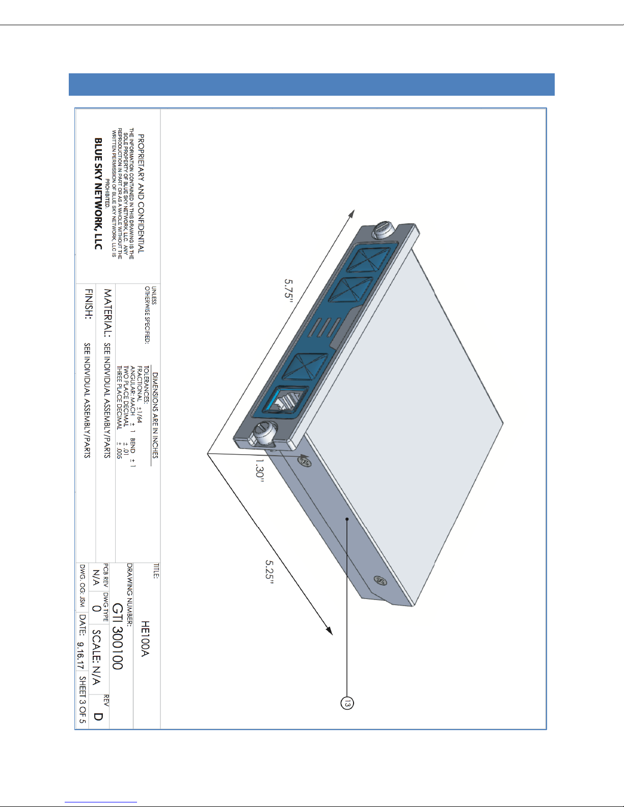
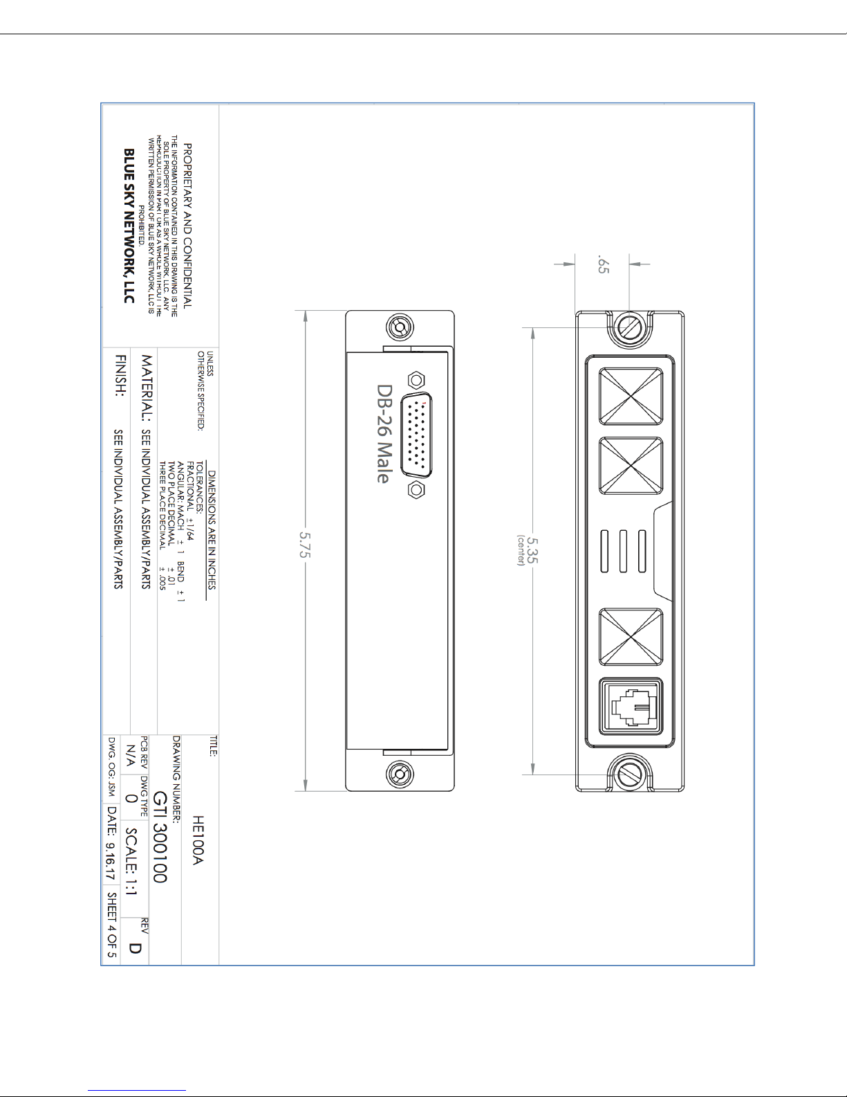
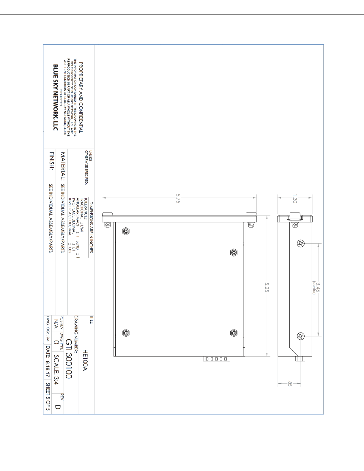
MECHANICAL SPECIFICATIONS
Blue Sky Network, LLC February 2018
HE100A Install Guide 15 Version 1.5
Blue Sky Network, LLC February 2018
HE100A Install Guide 16 Version 1.5

Blue Sky Network, LLC February 2018
HE100A Install Guide 17 Version 1.5
OPERATIONAL CHECK AND POWER-ON PERFORMANCE PROCEDURES
A functional ground test procedure and an operational flight check procedure should be used to verify
proper installation and functional performance. In order to accomplish a quick functionality check (after
installation is completed), position the aircraft outside of the hangar with no overhead obstructions. With
all other aircraft systems powered down, apply aircraft power to the HE7200A modem unit & HE100A
accessory system.
1. Observe the LED’s on the HE100A, immediately after being powered on they should be solid, and
then soon after that they should be blinking while the HE7200A is searching for signal. Ultimately
the Iridium and GPS lights should be solid green.
2. Attempt to place a call using any and all voice interfaces that may be required. Refer to the user
manual for dialing behaviors, but to dial a number you will need to press 00 + IDD prefix + phone
number followed by the # to initiate the satellite phone call. Ensure you can communicate with the
other side.
3. [OPTIONAL] Test the Bluetooth interface by activating the Bluetooth button on the HE100A and
then using an iOS device pair your phone with the phone and check the status screen for GPS
information and to ensure you can read the IMEI number from the HE7200A system.
If any difficulty is experienced with the functionality or operational performance of the HE7200A or the
HE100A, please contact Blue Sky Network for assistance.
The required logbook entries and FAA approvals are the responsibility of the installer and Blue
Sky Network, LLC assumes no responsibility for either obligation.

Blue Sky Network, LLC February 2018
HE100A Install Guide 18 Version 1.5
APPENDIX A – PRODUCT WARRANTY
PRODUCT WARRANTY
PLEASE READ -- THIS DOCUMENT CONTAINS IMPORTANT NOTICES, WARRANTY INFORMATION
AND LIMITATIONS ON YOUR RIGHTS
USE & INSTALLATION
The HE100A (“Product”) is intended to be used and installed on aircraft. Installation of this Product and
any of its component parts and any other work performed on the airframe during installation must be
performed in accordance with federal aviation administration (“FAA”) regulations and all other applicable
regulations and may require further FAA certification. This Product should be installed by a professional
and is intended to be handled and used solely in accordance with FAA regulations and the most recent
specifications and instructions distributed by Blue Sky Network, LLC (“Blue Sky”).
NO SUBSTITUTION ALLOWED FROM RECOMMENDATIONS WITHOUT Blue Sky Network LLC
PERMISSION, TO MAINTAIN EQUIPMENT WARRANTY.
FUNCTIONALITY
The functionality of this Product will, in significant part, depend on the service provider and the
communications network used in conjunction with this Product. To the extent Blue Sky is also your
service provider for this Product, then this Product is also subject to the terms and conditions of your
service contract.
LIMITED WARRANTY
This Product is the HE100A P/N: 300100.
Blue Sky is the original equipment manufacturer for the modem unit (the “Warranted Components”). Blue
Sky warrants that the Warranted Components shall be free from defects in materials and workmanship for
a period of six (6) months from the date this Product is delivered to the first end-user purchaser
(“Purchaser”) or the date this Product is first placed into satellite subscriber service, whichever occurs
earlier. This warranty is not assignable or transferable by the Purchaser.
Blue Sky, at its option, shall at no charge to Purchaser either repair or replace Warranted Components
that do not conform to this warranty, provided that the Warranted Components are returned in
accordance with the instructions set out below and within the warranty period. These remedies are
Purchaser’s exclusive remedies under this warranty. Repair may include the replacement of parts with
functionally equivalent reconditioned or new parts. Warranted Components that have been repaired or
replaced are warranted for the balance of the original warranty period. All Warranted Components for
which replacements have been provided shall become Blue Sky’s property.
Blue Sky does not manufacture the antenna and therefore Blue Sky is not providing any warranty
concerning this component. To the extent the manufacturer warrants the antenna and such warranty may
be assigned and passed through to Purchaser, such warranty shall be assigned by Blue Sky and passed

Blue Sky Network, LLC February 2018
HE100A Install Guide 19 Version 1.5
through to the Purchaser. The Purchaser must deal directly with, and Blue Sky accepts no responsibility
regarding the actions of, the manufacturer of the antenna.
Blue Sky does not warrant any installation, maintenance, or service of this Product or any component
thereof not performed by Blue Sky.
Blue Sky is not responsible in any way for any damage to ancillary equipment or software which is
attached to or used in connection with this Product, or for operation of this Product with any ancillary
equipment or software, and all such equipment and software are expressly excluded from this warranty.
Furthermore, Blue Sky is not responsible for any damage to this Product.
BLUE SKY ASSUMES NO RESPONSIBILITY FOR PAYMENT OF ANY REPAIR SERVICES
PERFORMED BY THIRD PARTIES INCLUDING REMOVAL OF THE UNIT FROM THE AIRCRAFT,
INSPECTION, PACKAGING, HANDLING, OR INSTALLATION UNLESS SUCH SERVICES ARE
AUTHORIZED IN ADVANCE AND IN WRITING BY BLUE SKY.
HOW TO GET WARRANTY SERVICE
Warranty service is available by contacting Blue Sky at the following telephone number (during business
hours) or email address or by returning the Warranted Components to Blue Sky at the following address:
Blue Sky Network, LLC.
5333 Mission Center Rd. #220
San Diego, CA 92108, USA
Phone: +1-858-551-3894
E-mail: support@blueskynetwork.com
Purchasers are advised to contact Blue Sky at the above telephone number or email address for a
consultation prior to returning Warranted Components. All Product shipped to Blue Sky must be shipped
with freight, duties, and insurance prepaid. Purchaser must include with the Product a bill of sale (or other
comparable proof of purchase), the Purchaser’s name, address and telephone number, the tail number
and serial number of the aircraft on which the Product was installed and a detailed description of the
problem. Warranted Components that are repaired or replaced under this limited warranty shall be
shipped to Purchaser at Blue Sky’s expense for the freight and insurance and at Purchaser’s expense for
any applicable duties or other expenses of shipment.
Blue Sky reserves the right to make changes, upgrades, and improvements to this product without
incurring any obligation to install such changes, upgrades, and improvements in previously manufactured
products.
ANY SERVICE WORK PERFORMED BY A PARTY OTHER THAN BLUE SKY OR BY A PARTY NOT
OTHERWISE AUTHORIZED BY BLUE SKY SHALL IMMEDIATELY VOID THIS LIMITED WARRANTY.
Please contact Blue Sky Network, LLC if you have any questions regarding Blue Sky’s limited warranty.
DISCLAIMERS & LIMITATION OF LIABILITY
EXCEPT FOR THE LIMITED WARRANTY SPECIFICALLY PROVIDED HEREIN, ALL OTHER
WARRANTIES ARE EXPRESSLY DISCLAIMED, INCLUDING, WITHOUT LIMITATION, WARRANTIES
OF MERCHANTABILITY AND FITNESS OR SUITABILITY FOR A PARTICULAR PURPOSE. ANY

Blue Sky Network, LLC February 2018
HE100A Install Guide 20 Version 1.5
LIABILITY SHALL BE LIMITED EXCLUSIVELY TO REPLACEMENT OR REPAIR OF THE
WARRANTED COMPONENTS AS PROVIDED HEREIN. UNDER NO CIRCUMSTANCES SHALL
LIABILITY EXIST FOR INCIDENTAL, CONSEQUENTIAL, OR SPECIAL DAMAGES RELATING TO THE
HANDLING, INSTALLATION OR USE OF THIS PRODUCT. BLUE SKY SHALL NOT BE OBLIGATED
OR LIABLE FOR, AMONG OTHER THINGS, DEFECTS CAUSED BY TAMPERING, MISUSE,
ACCIDENT, ABUSE, NEGLECT, IMPROPER STORAGE OR MAINTENANCE, USE IN A MANNER
BEYOND WHICH THIS PRODUCT IS INTENDED TO BE USED AS SET FORTH IN BLUE SKY’S
SPECIFICATIONS, IMPROPER REPAIR, POOR WORKMANSHIP OR USE OF DEFECTIVE
MATERIALS BY SOMEONE OTHER THAN BLUE SKY, OR ANY OTHER CAUSE EXCEPT FOR
DEFECTS IN MATERIALS OR WORKMANSHIP WITH RESPECT TO THE WARRANTED
COMPONENTS AS DELIVERED BY BLUE SKY.
Some states do not allow the exclusion or limitation of incidental or consequential damages and some
states do not allow limitations on how long an implied warranty may last; therefore, the above limitations
or exclusions may not apply to you. The warranty provided herein gives you specific legal rights. You may
also have other rights that vary from state to state. In the event any of the provisions of the limited
warranty are found by statute or by applicable
This manual suits for next models
1
Table of contents
Other Blue Sky Network GPS manuals

Blue Sky Network
Blue Sky Network HawkEye 7200A-BB2327 User manual

Blue Sky Network
Blue Sky Network HAWKEYE PT PLUS User manual

Blue Sky Network
Blue Sky Network D1000 Series User manual

Blue Sky Network
Blue Sky Network HawkEye Plus User manual

Blue Sky Network
Blue Sky Network HawkEye 6300 Mk1 User manual

Blue Sky Network
Blue Sky Network HawkEye 7200 Quick start guide

Blue Sky Network
Blue Sky Network D411 User manual

Blue Sky Network
Blue Sky Network HawkEye 7200 Operating instructions

Blue Sky Network
Blue Sky Network HawkEye 6200 User manual

Blue Sky Network
Blue Sky Network SKYLINK User manual


